Week 1: Computer-Controlled Cutting
The assignment for this week was to characterize the laser cutter create a press fit kit to be cut in the laser and cut anything with the vinyl cutter.
Assignment 1: Press Fit Kit
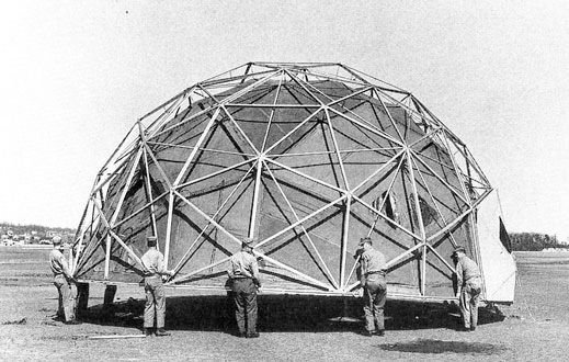
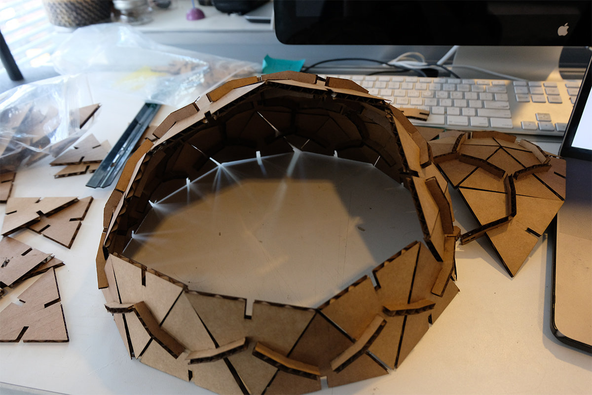
For this week's assignment I decided to design and make a press fit geodesic dome. The geodesic dome a geodesic polyhedron that distribute the stress across the the panels that make it's surface. The geodesic dome was designed by Walther Bauersfeld after the First World War, but gained popularity after Buckminster Fuller brought the design to the US.
Design
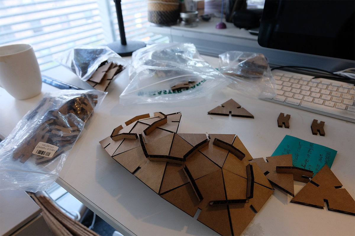
The design structure of a 2v geodesic dome is made up of two panels, Y Panel and X Panel. Where the two triangles have the following geometric relationships. The A and B dimensions of the triangles are governed by the formulaes:
A_Length = DomeDiameter / 2 * 0.54653 B_Length = DomeDiameter / 2 * 0.61803
For the assignment I decided to create a dome with 30cm diameter. Based on this diameter I used the formulas to calculate the the lenghts of the triangles. I found this reference useful to confirm my calculation and to define the number of each panels.
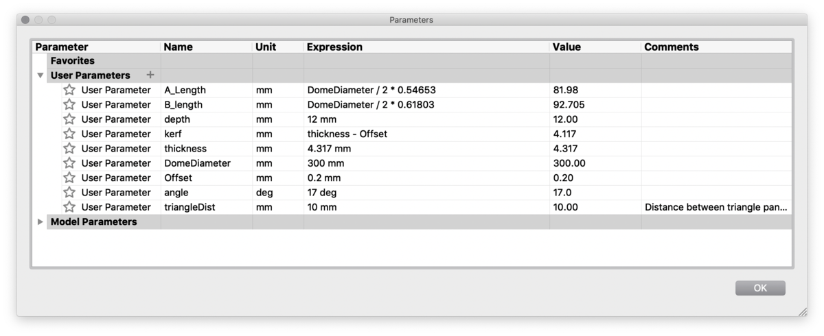
Parametric Modeling
Based on the carboard thickness, the A and B lenghts of the triangles I created a table with the parametric properties of the triangles based on the geodesic dome formula. I measured the thickness of the carboard and used the thickness and the laser offset to calculate the size of the kerf. I choose a arbitrary value for the depth of the kerf.
Learning from Mistakes
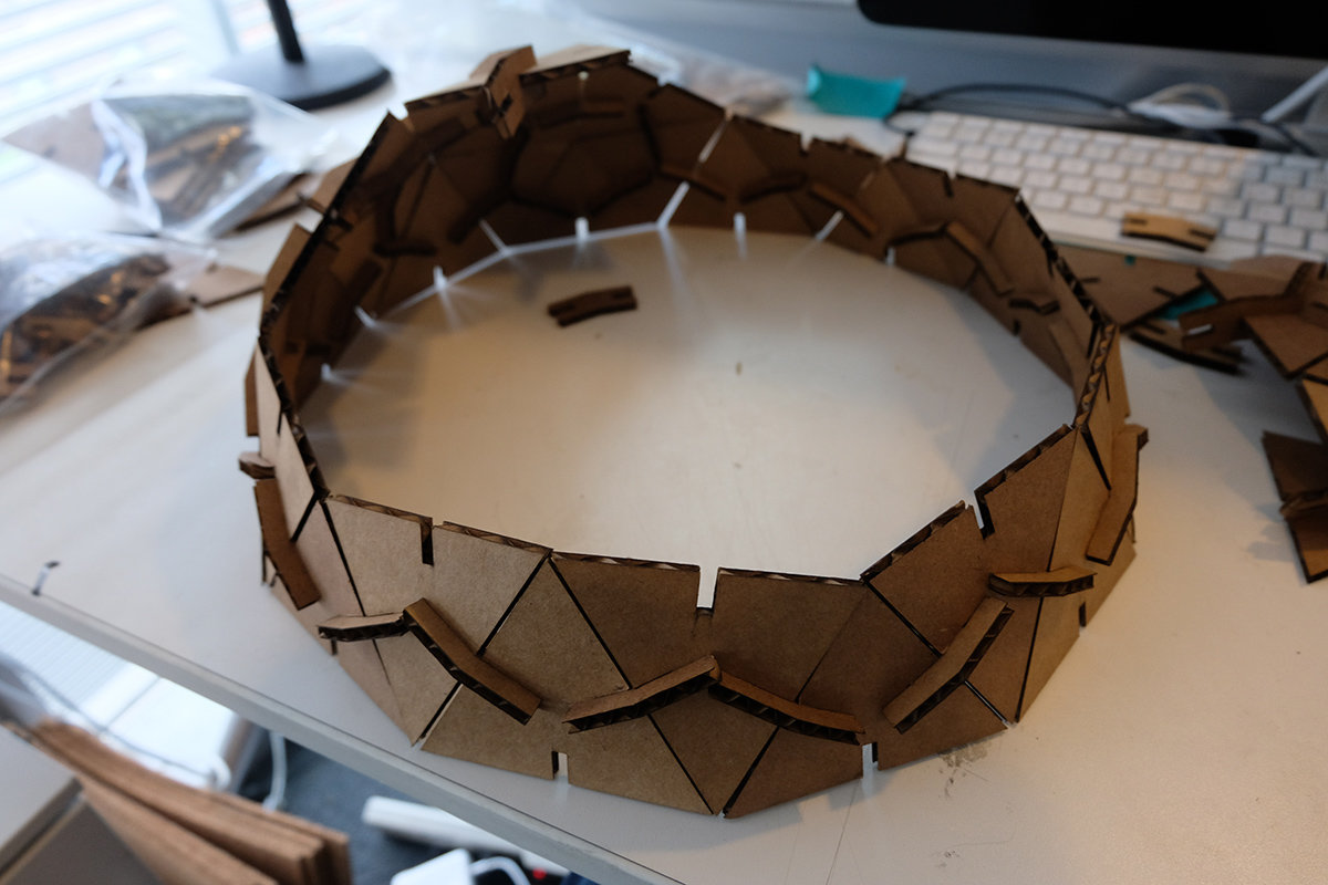
I had initially made a mistake of having an angle of 18 degrees for both sides of the joint. Below there's an image of my first panel with the incorrect joints. When assembling the first prototype I realized that doubling the angles made the geodesic dome shape close into a smaller polyhedron.
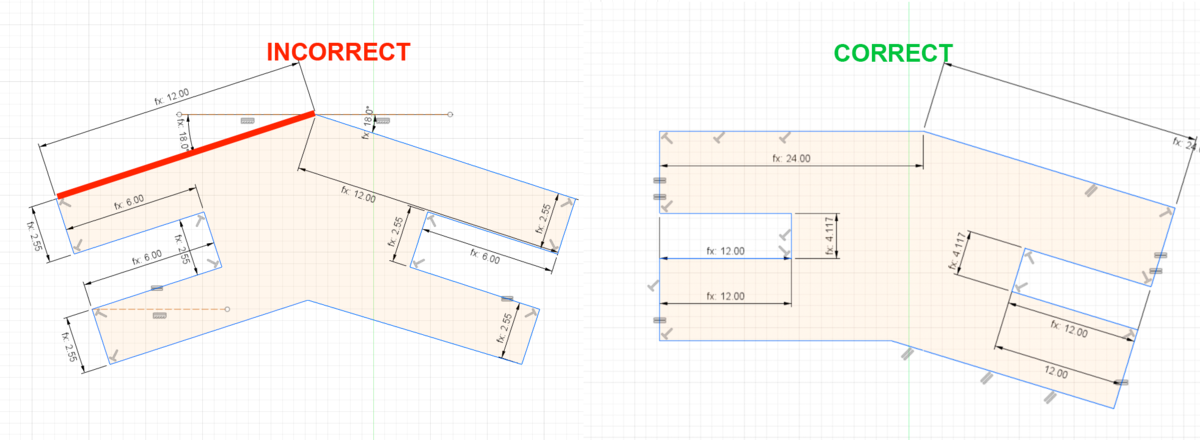
My workflow was to design the primitives (2 triangles and joint) in Fusion 360. Export those as DXF and using Illustrator and Corel Draw I paneled them into the final design trying to be more resourceful with space to save material. I then went back into Fusion 360 and corrected the mistake on the joint. Which led me to create the final panel.
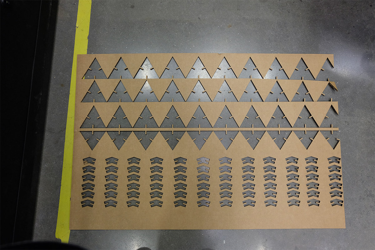
Final Design
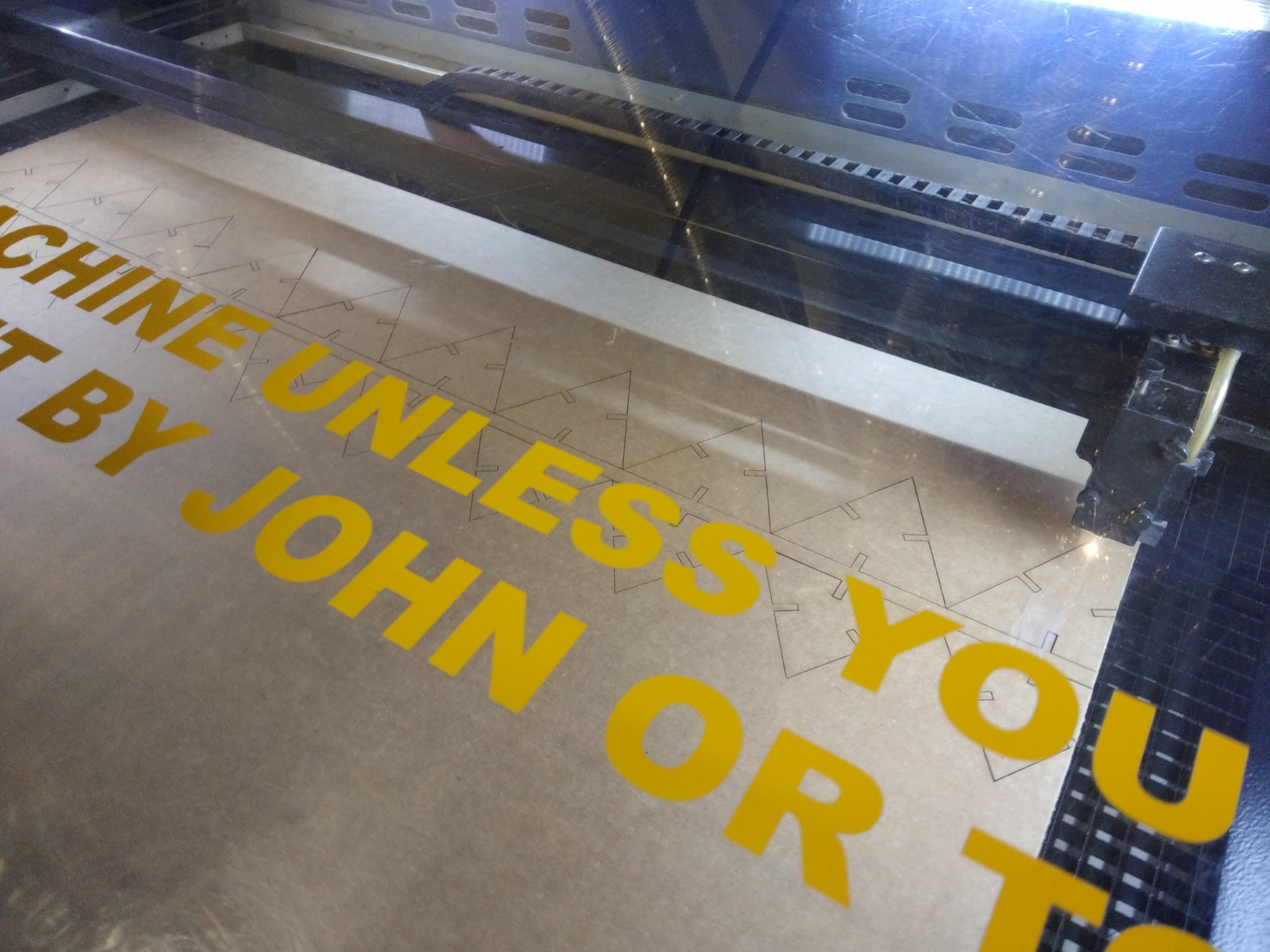
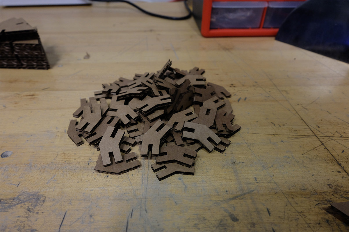
The settings used on the laser cutter for cutting the cardobard was: Speed: 1.5, Power:100, PPI 300. This settings successifully cut the cardobard without any issues. After correcting my mistake on the joint I produced another panel with the correct structure and started assembling the dome. I used a guide to assemble the demo and followed the structure suggested in the guide to correctly attach the Y and X panels.
Assignment 2: Vinyl Cutter
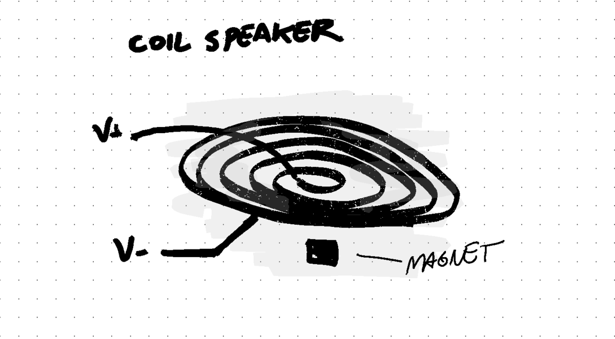
Most coil based speakers work through the same principle of using a electromagnetic coil that is connected to a voltage source with the audio signal and a static magnet. Based on this principle I wanted to vinyl cut copper to create a sheet speaker.
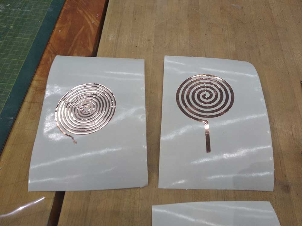
First I did a series of studies of different coil turns and trace thicknesses starting with very large features (10mm) and low number of turns (20cm) I then gradually increased the number of turns and reduced the feature size.
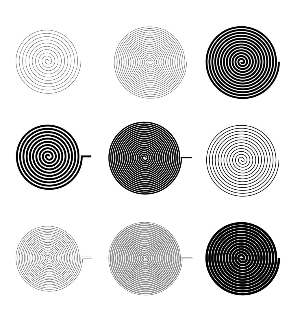
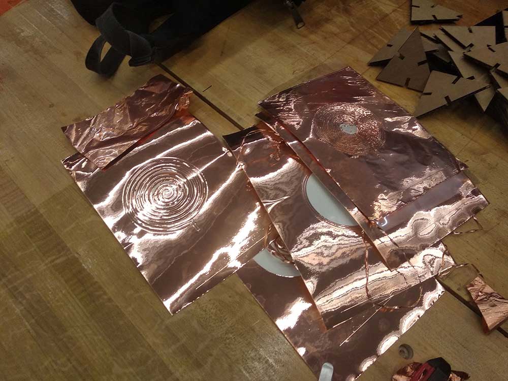
Based on my studies I ran a number of tests on the vinyl cutter using a speed of 5 and pressure 80g/f. I first did some tests with the very large features which resulted in some good cuts as seen below.
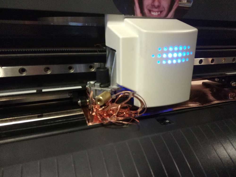
I realized that the copper was coming out from the adhesive paper and when cutting smaller features the copper would get stuck on the blade which would completely destroy the design.
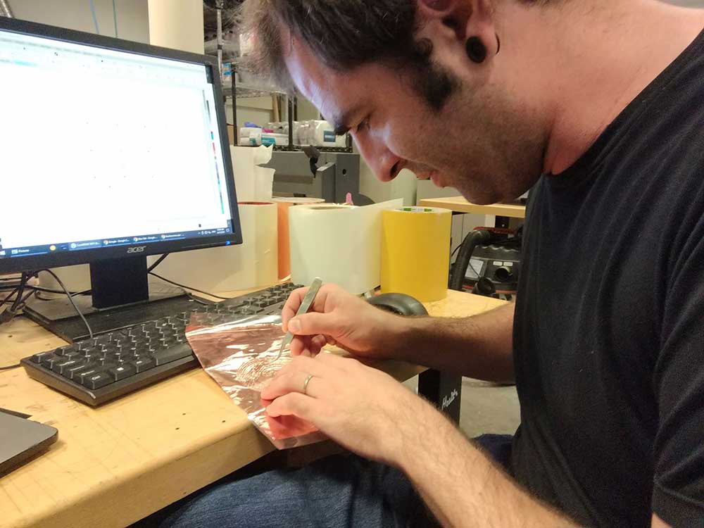
Following an advice from Tom removed the copper foil from it's initial surface and stuck it to a piece of thin film which increase the adherence of the copper to the substrate. I then used the cutter with a speed of 5 and 60g/g which gave me the best results. After a patient moment of peeling the unused copper parts I got to see my design.
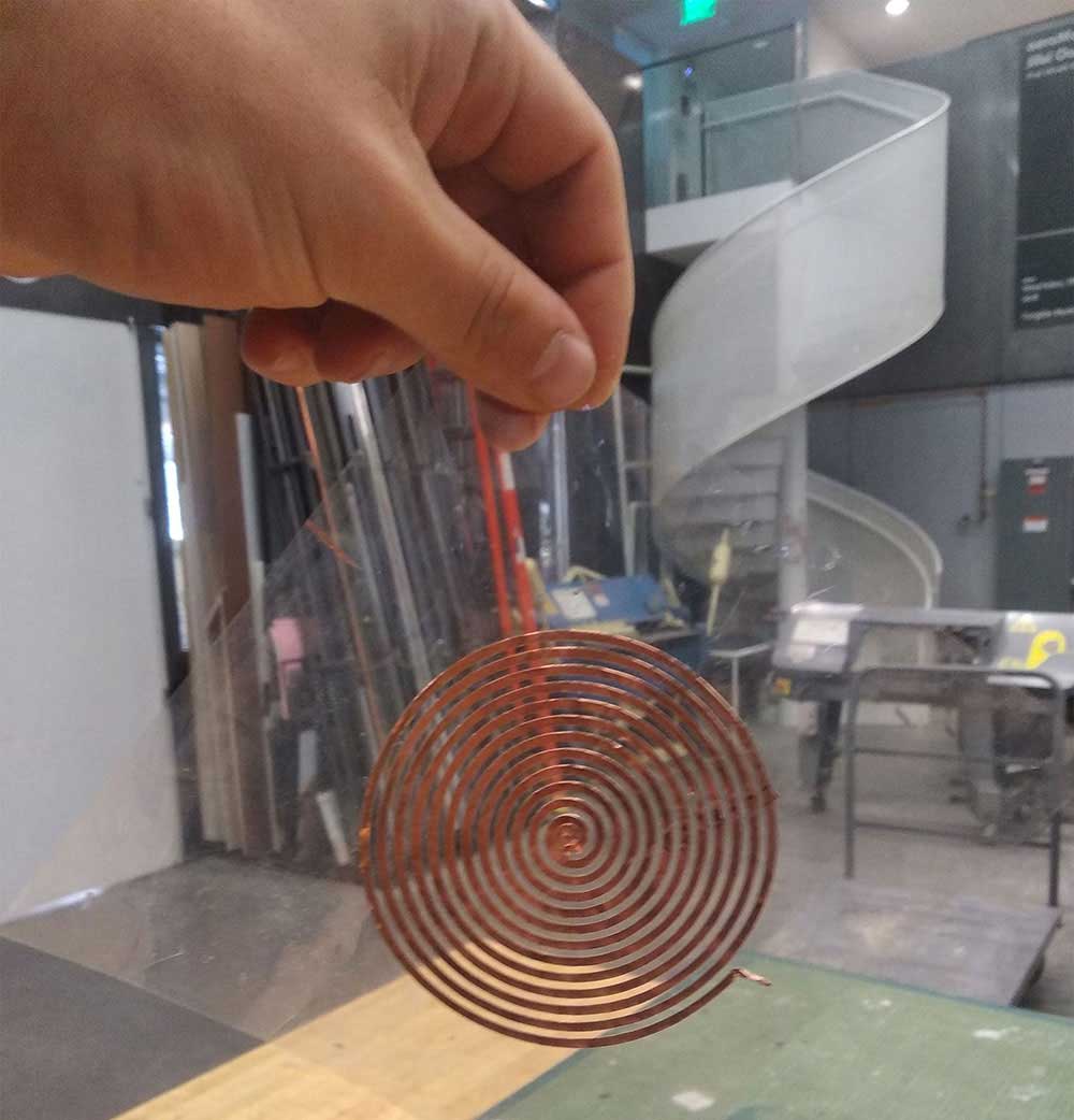
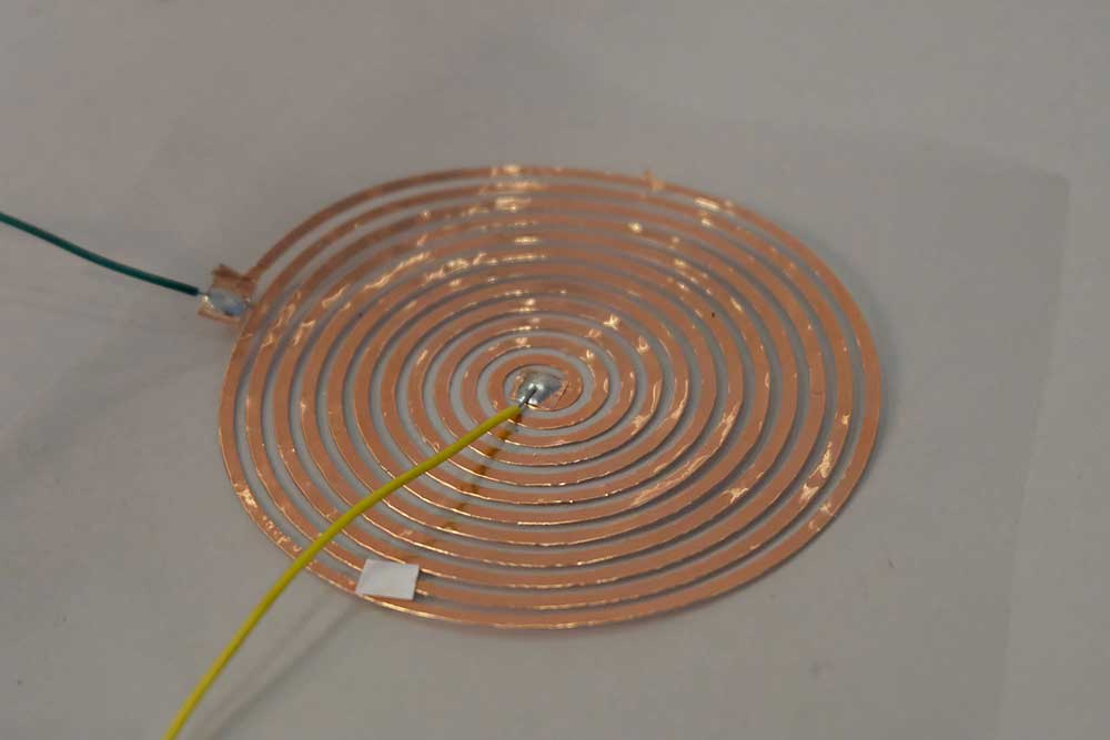
I connected the coil to an amplifier and you can now hear my speaker.