Week 6: Embedded Programming
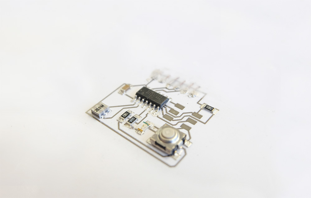
For this week our task was to read a datasheet for the ATTiny44 and program our board created in the electronics design week to do something, For this week I decided to do something very simple with the button on my board (making it switch an LED on and off ) and focus most of my time in trying to move the board from hard copper to a flexbile substrate such as paper. This is is necessary for my final project.
Programming the Board
I wrote a C code for the LED to be switched on when the button is pressed. For that I started with a very simple C program that sets the pins to output and in the main loop (inside while) it checks (with a conditional) for a button press and sends a high to the output port where the button is connected.
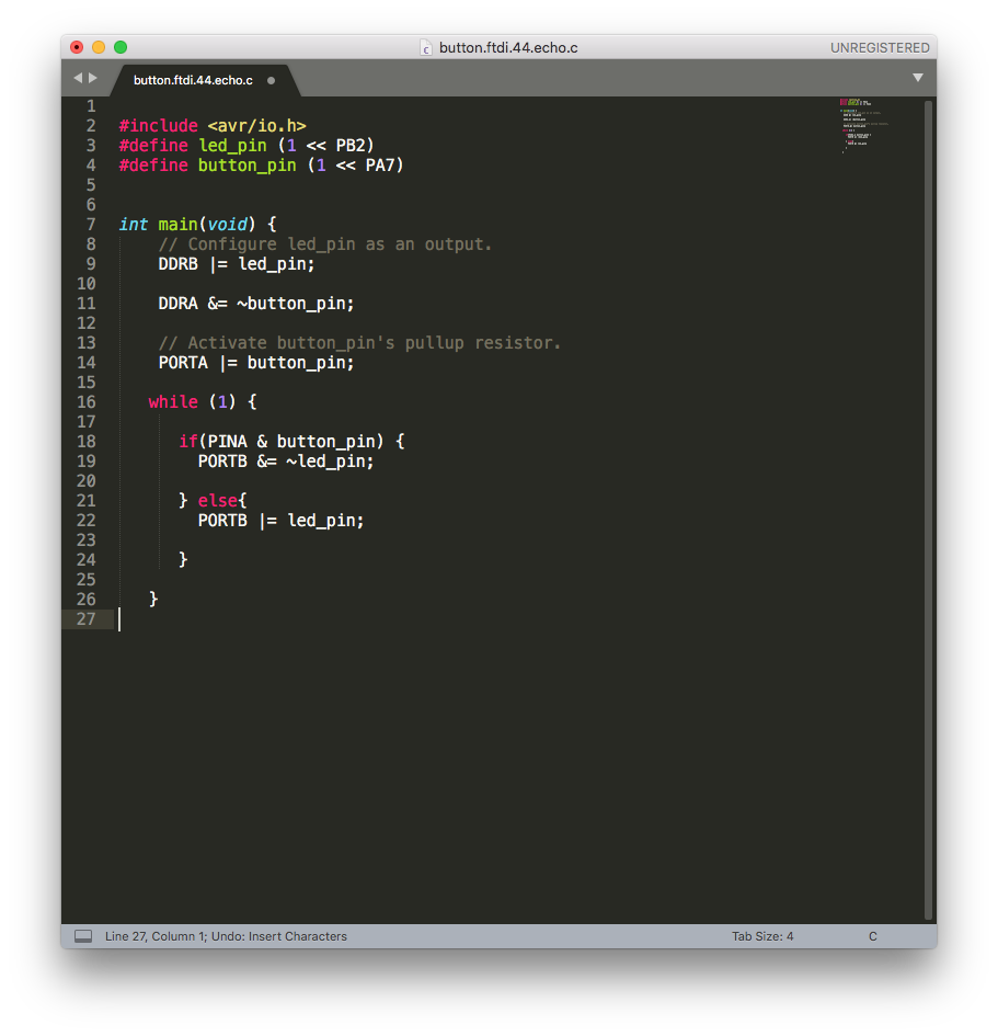
I had my led connected to PB2 and the button to PA7. On lines 9 and 11 of the screenshot I sent the ports as output and input respectively and on the while loop I check with the & operator.
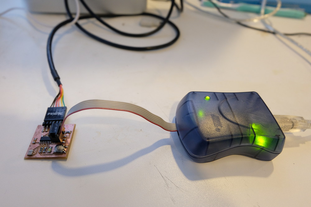
I then compiled the program using the makefile and programmed the boad using the AVR dude programmer. First connected the AVR programmer to the 6header pin of the board. I then connected the FTDI cable to the computer USB.
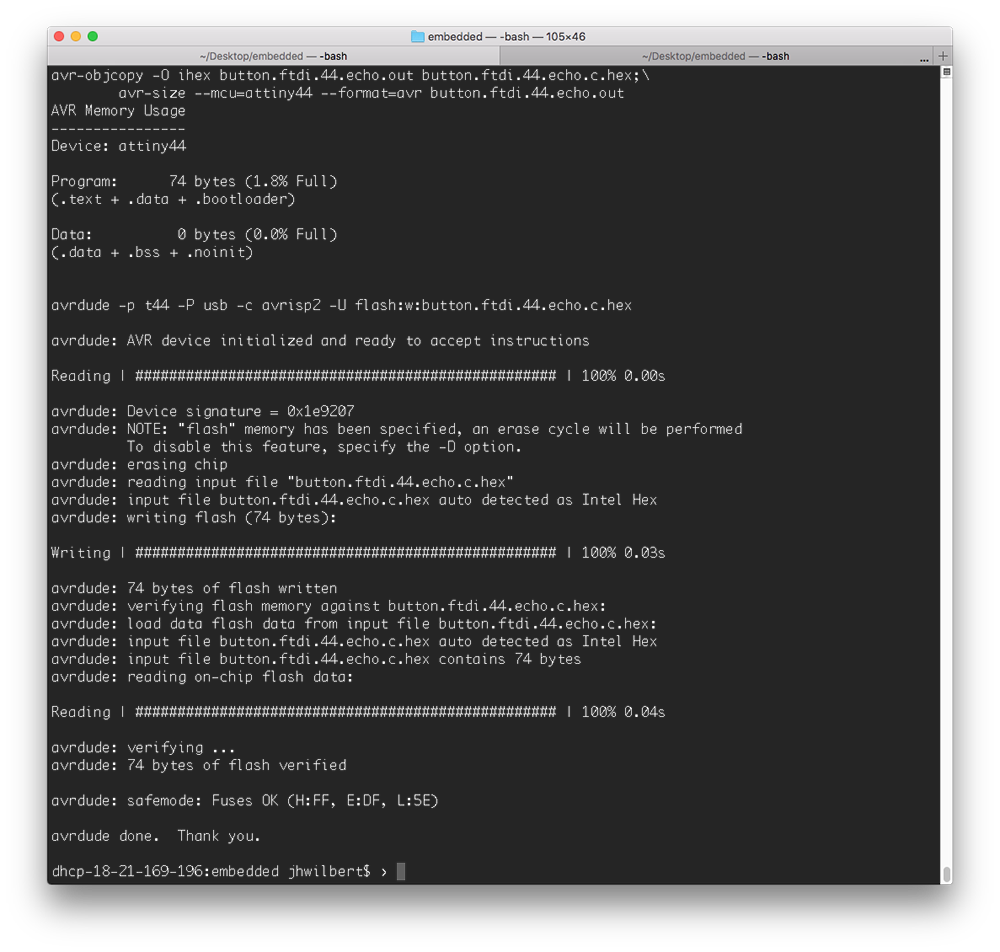
After creating my code I then ran:
$ make -f hello.ftdi.44.echo.c.make$ sudo make -f button.ftdi.44.echo.c program-avrisp2
The image below shows the result on my console. The board was programmed succecssifully I could turn on the LED. I also did the inverse, where the LED was always on and by pressing the button the LED switches off.
The first video shows the board waiting for a button press to switch on the LED.
The video below is the opposite, where LED is always on and holds until the button is pressed to switch the LED off.
Making Paper Circuits
This is something that I have been wanting to try for a long time and it's part of my final project. I decided to port the design to a printed circuit on paper. As a challenge to myself I didn't want to scale up but try to transfer the board as is.
My strategy was to print the circuit in two ways, using the vinyl cutter and the inkjet printer I hacked to use conductive ink for printing. After printing the bottom traces on paper I then planned to use laser cut a solder mask to apply Conductive Epoxy to the circuit. After applying the epoxy to the pads I would then carefully place the components.
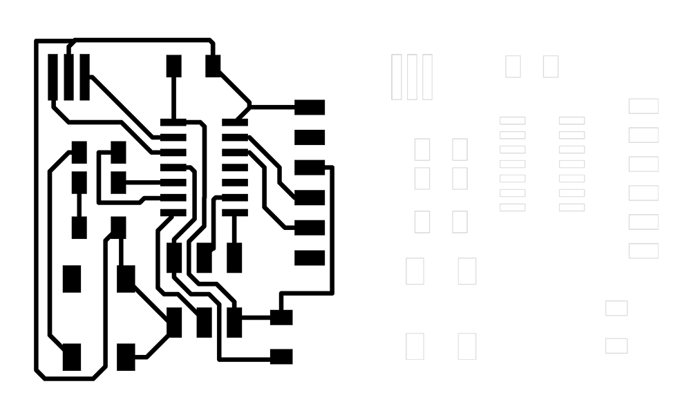
Circuit Design
On Eagle I exported the traces as PNG and and solder mask as a vector. I did the traces width a little larger to account for some imperfection on the printing or vinyl cutting side. Note that on the mask I am not exposing the 6-pin header - the reason is that my plan is to just use it as a contact with the the 6 pin header cable not needing solder at that point.
Experimenting with Vinyl Cutter
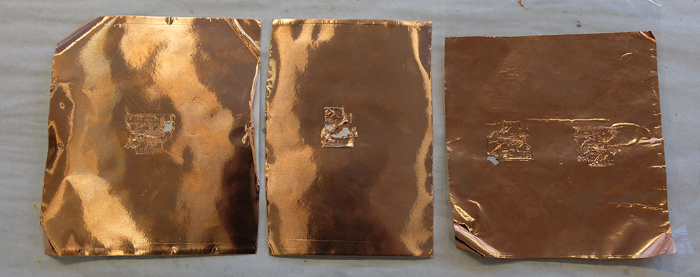
I tried experimenting with the vinyl cutter with different pressure, speed and varying the blade height (manually). I didn't have great results. Most of the time the blade would cut the traces with imperfections which would eventually lead to it ripping off the traces.
I attempted by moving the copper foil from it's original substrate to a PET film (to increase adherence), that also didn't help. I then gave up on using the vinyl cutter (for now at least) and moved on to try the inkjet printer I have.
Printing with the Inkjet Printer
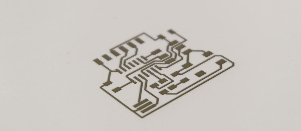
I printed using the Brother Inkjet Printer in my lab. Brother DCP-J140W inkjet and Mitsubishi NBSIJ-FD02 with Silver Nanoparticle Ink printed on A4 sheet of Mitsubishi NB3GR Resin Coated Paper.
My first run was a good success, I could see the traces very clearly and well defined in the print. For this first try I just printed once, when looking through the microscope I could see that the conductive ink was somehow granulated and not forming a uniform layer. But when probing with the multimeter I could get continuity in all traces.
After having the traces printed I then moved on to laser cut the mask. I used Kapton film XXXmil for my mask. Given to some export setting on Eagle I had to scale the mask down on Corel Draw by 50% to get an exact match with the size of the printed traces.
The mask laser cut was good resolution enough for me to move on to the next step which was to attach and register it with the printed traces.
I attached the mask to the paper using some Kapton tape and was careful to make sure that the pad holes in the mask were aligned with the solder points on the paper layer.
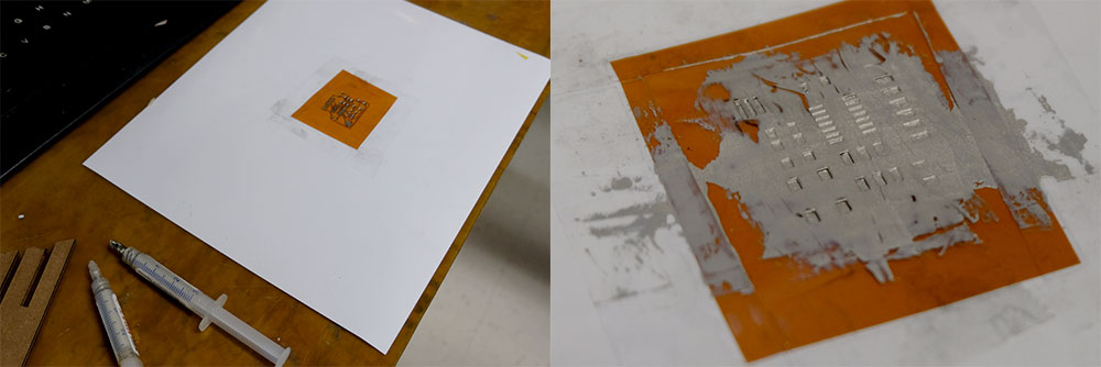
I then prepared a mix of 1:1 silver epoxy that cures at room temperature and using a credit card I swept the conductive epoxy paste over the mask. I was careful to let the epoxy overflow a little over the mask to have more 'meat' for the components to land on it.
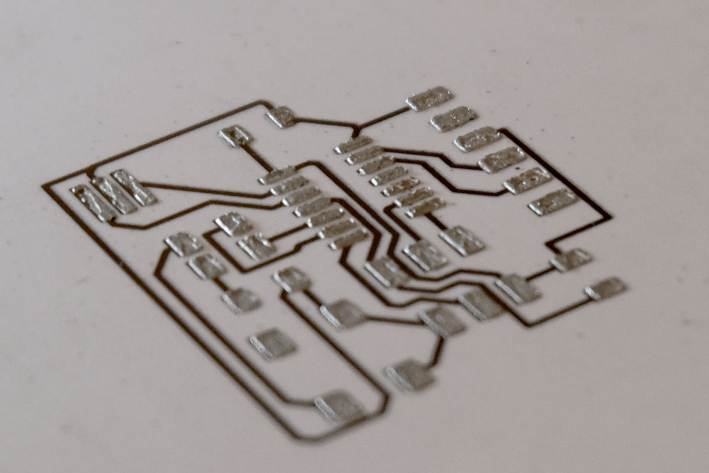
With this technique I could get a relatively good result - all the pads where correctly covered by solder paste. I then proceeded to add the components. The technique to add the components is to carefully using two tweezers one to hold the component and place in the desired location and a second tweezer to hold the component down as the first tweezer is pulled. This helps the components stay in place.
Failures and Successes
Prototype v1
The very first prototype was somehow a failure. I realized that trying to add the 6 header pin was not a good idea as the part is too heavy and the mechanical stress of connecting and disconnecting the pin header would make the epoxy break out from the traces, so I decided to do without prototype. I also smudged the epoxy when placing the microcontroller shorting the pins.
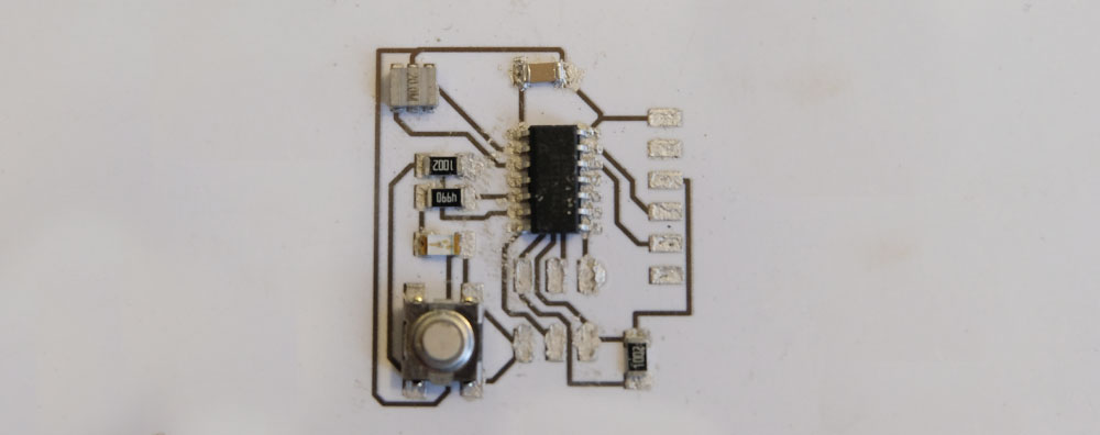
Issue: smudged conductive epoxy when trying to attach microntroller shoring the pins. Fix: be more careful as it's a one shot chance. Also I realized that adding the 6 pin header here is pointless.
Prototype v2
This prototype was somehow successful, I used a flatcable to reach the FTDI pads and instead of using the 6-header pin I simply attached the 6 header to the flatcable of the AVRISP2 programmer and touched the pads. By doing many times it ruined the pad connections.
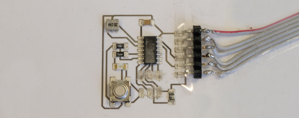
Issue: connector to FTDI was too bulky and not all pins where connected. The other issue was by forcing the pins to not adhere to the surface. Fix: use a very thin gauge wire and pierce it through the paper to reach the pad (mechanical stability) - thanks Zach Fredin for the tip! :)
I tried programming it and I could get it programmed the first time around but couldn't program it any further. When moving around the FTDI cable I could see the LED light up which means that it was powered up.
Prototype v3
For the third prototype I used thin insulated copper wire going through the paper to reach the prototype. I also decided to not apply solder mask to the 6pin-header pads, but instead cut very small slices of conductive textile tape and attach it tot he paper.