Input Devices
Files: hello.temp.45.traces; hello.temp.45.interior; hello.temp.45.c; hello.temp.45.make; hello.temp.45.py.
This week we’re exploring input devices, i.e. how our microcontroller boards can start sensing the physical world. For my final project I need different sensors for monitoring water quality characteristics including temperature, turbidity and electrical conductivity. Temperature is one of the most important water characteristics, as it affects the dissolved oxygen levels (oxygen solubility decreases as water temperature increases), the solubility and reaction rates of chemicals (rate of chemical reactions increases with increasing water temperature), biological processes (metabolism, growth, and reproduction), species composition of the aquatic ecosystem, as well as water density and stratification. A temperature sensor seems pretty straitforward to build and use, so I decided to make one this week.
PCB Design
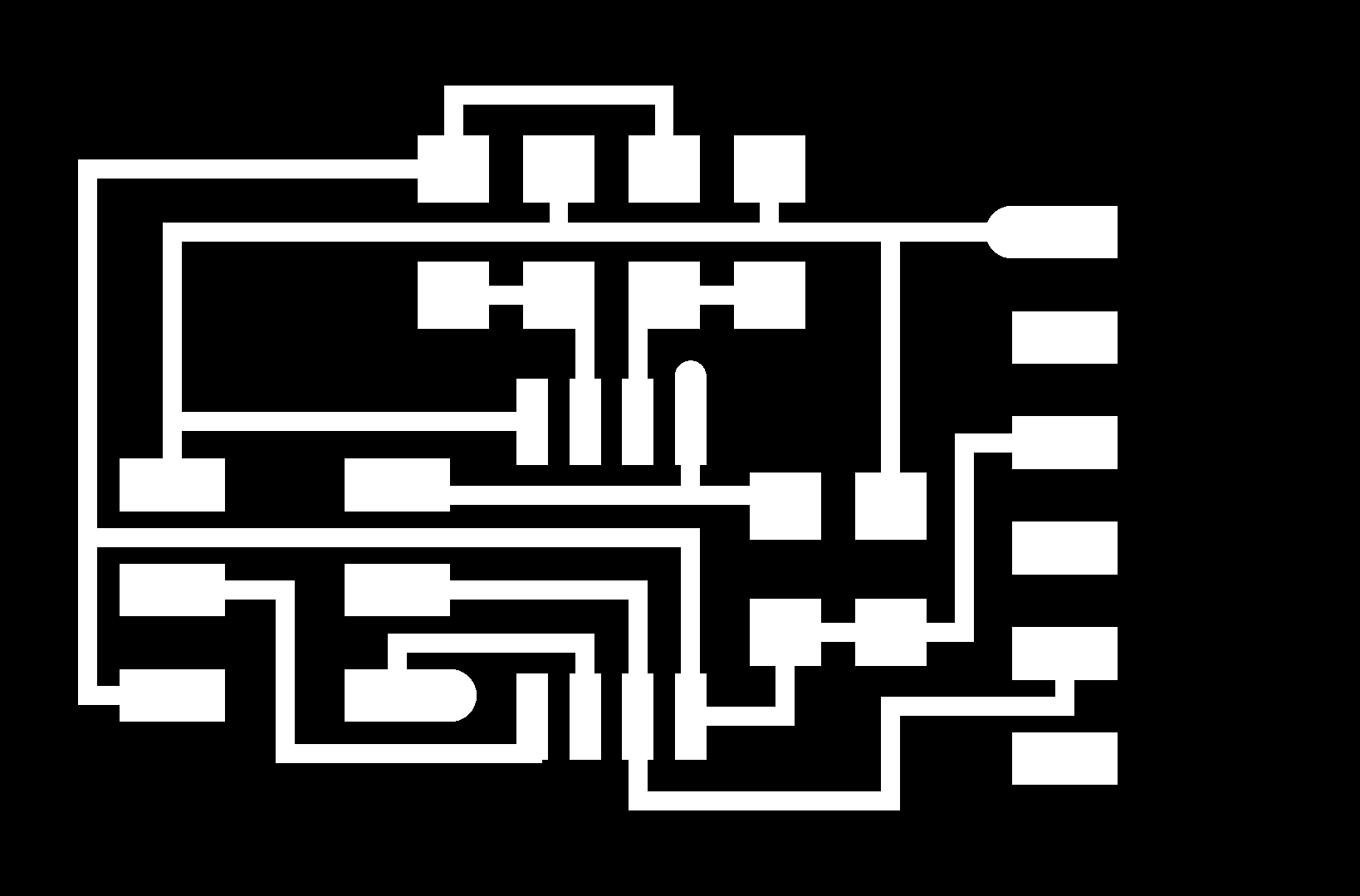
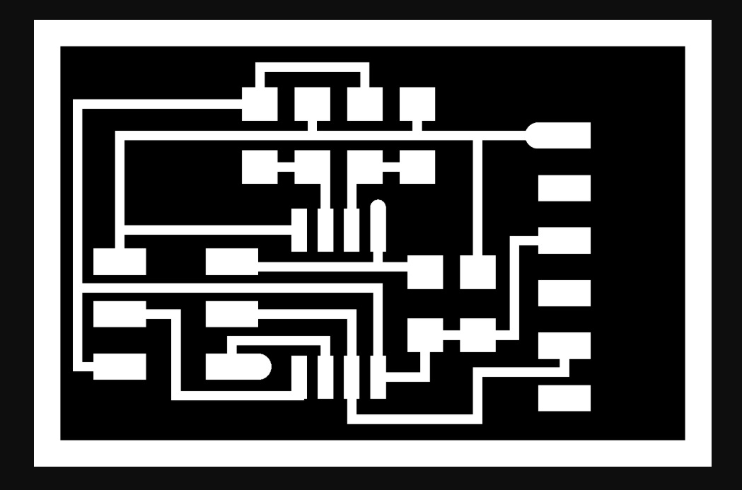
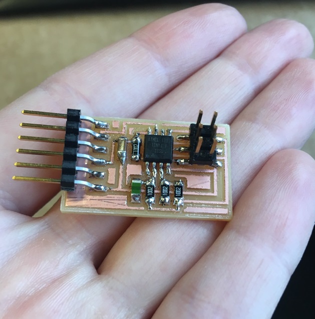
I used Neil's design for the temperature sensor board "hello.temp.45". The board, its traces and its interior are shown below:
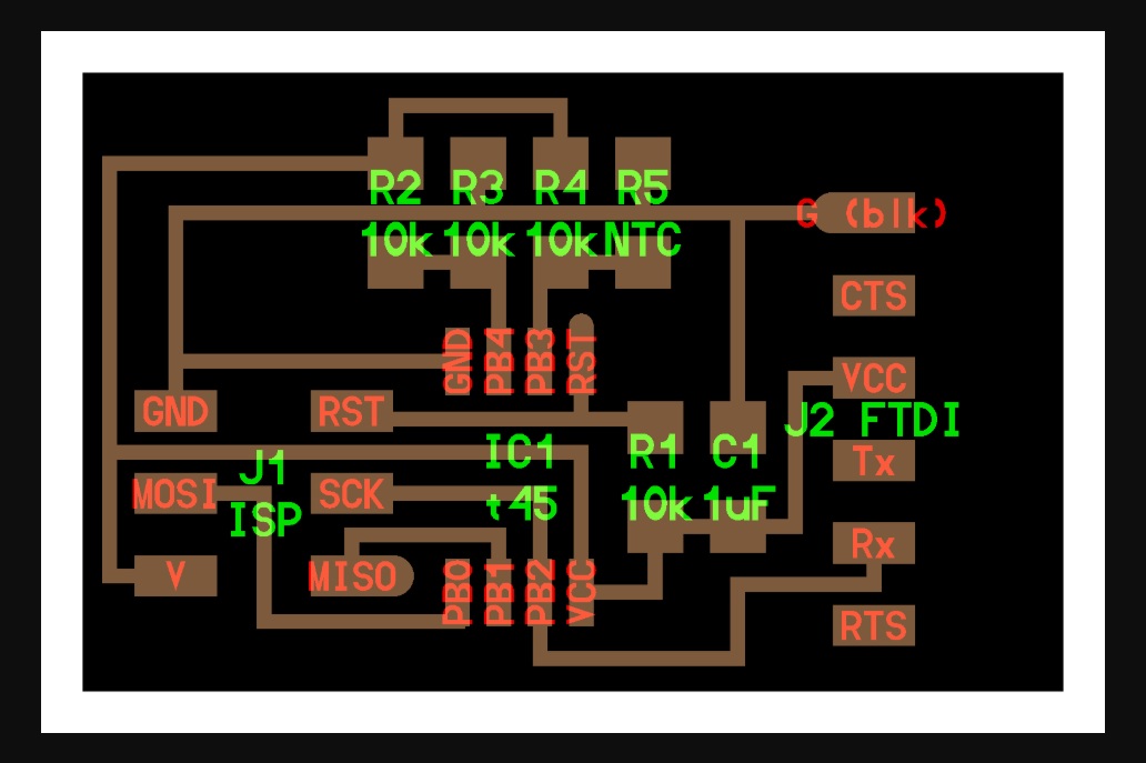

The necessary components for producing the board are the following:
- 1x ATtiny45
- 4x 10kΩ resistor
- 1x 1μF capacitor
- 1x 2x3 pin ISP header
- 1x 1x6 pin male connector (FTDI)
- 1x NTC THERMISTOR 10kΩ 3750K 1206
The NTC thermistor is the component that senses the temperature. I read some usefull info in order to understand how this tiny component works (see below).
NTC Thermistor
The word thermistor, derived from the term thermally sensitive resistor. Thermistors are a type of semiconductor, meaning they have greater resistance than conducting materials, but lower resistance than insulating materials. They are very accurate and cost- effective sensors for measuring temperature.
The thermistor is basically a two-terminal solid state thermally sensitive transducer constructed using sensitive semiconductor based metal oxides with metallised or sintered connecting leads formed into a ceramic disc or bead. This allows the thermistor to change its resistive value in proportion to small changes in ambient temperature. In other words, as its temperature changes, so too does its resistance.
Thermistors are available in 2 types, NTC (negative temperature coefficient) and PTC (positive temperature coefficient). NTC thermistors’ resistance decreases as their temperature increases, while PTC thermistors’ resistance increases as their temperature increases. It is the NTC thermistor that is commonly used to measure temperature.
NTC thermistors have a negative electrical resistance versus temperature (R/T) relationship. The relatively large negative response of an NTC thermistor means that even small changes in temperature can cause significant changes in their electrical resistance. This makes them ideal for accurate temperature measurement and control. If we send a constant current through the thermistor and then measure the voltage drop across it, we can determine its resistance at a particular temperature. NTC thermistors reduces its resistance with an increase in temperature and are available in a variety of base resistances and temperature curves. NTC thermistors are usually characterised by their base resistance at room temperature, that is 25oC (77oF), as this provides a convenient reference point. So for example, 2kΩ at 25oC, 10kΩ at 25oC or 47kΩ at 25oC, etc. Another important characteristic of a thermistor is its “B” value. The B value is a material constant which is determined by the ceramic material from which it is made. It describes the gradient of the resistive (R/T) curve over a particular temperature range between two temperature points. Each thermistor material will have a different material constant and therefore a different resistance versus temperature curve. Then the B value will define the thermistors resistive value at a first temperature or base point, (which is usually 25oC), called T1, and the thermistors resistive value at a second temperature point, for example 100oC, called T2. Therefore, the B value will define the thermistors material constant between the range of T1 and T2. That is BT1/T2 or B25/100, with typical NTC thermistor B values given between 3000 and 5000.
Thermistor Equation
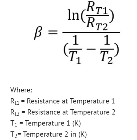
So by knowing the B value of a particular thermistor (obtained from manufacturers datasheet), we can calculate the resistance of the thermistor for a given temperature and vice versa, and develop the curve of temperature versus resistance.
More information on thermistors can be found here and here.
PCB Production
I used the Roland SRM-20 milling machine, controlled with mods to mill the board, following the same process as in Electronics Design week.
Then I soldered the necessary components on my board.
Programming
I used the USBtiny board, which I made during the Electronics Production week to program my board. I used an FTDI cable (5V) to connect my board with my computer (black wire on the FTDI cable was connected to GND) and an ISP cable to connect the board with the USBtiny programmer (the USBtiny was also connected with my computer). The orientation of the ISP cable was selected in such a way that the cable connected to GND pin in the board (purple cable) to be connected also to GND in the other board. I followed the same procedure as in the Electronics Design week, using Neil's c code and make file to program the board and saved them in a specific directory inside the C folder. I opened Git Bash and went inside the directory where the c code and the make file where located. Then, I ran the following commands:
- make -f hello.temp.45.make (in order to produce the hex file);
- make -f hello.temp.45.make program-usbtiny (flashing of the microcontroller).
Sensing
Then I removed the USBtiny programmer and left only the new board connected to my computer through the FTDI cable.
In order to run Neil's python file and view the thermistor sensing I had to download Python first. I went to Python's site and downloaded Python 3.8 and tried to run Neil's file using the following youtube video . However, I got several errors regarding syntax mistakes in the code and I coundn't run the file.
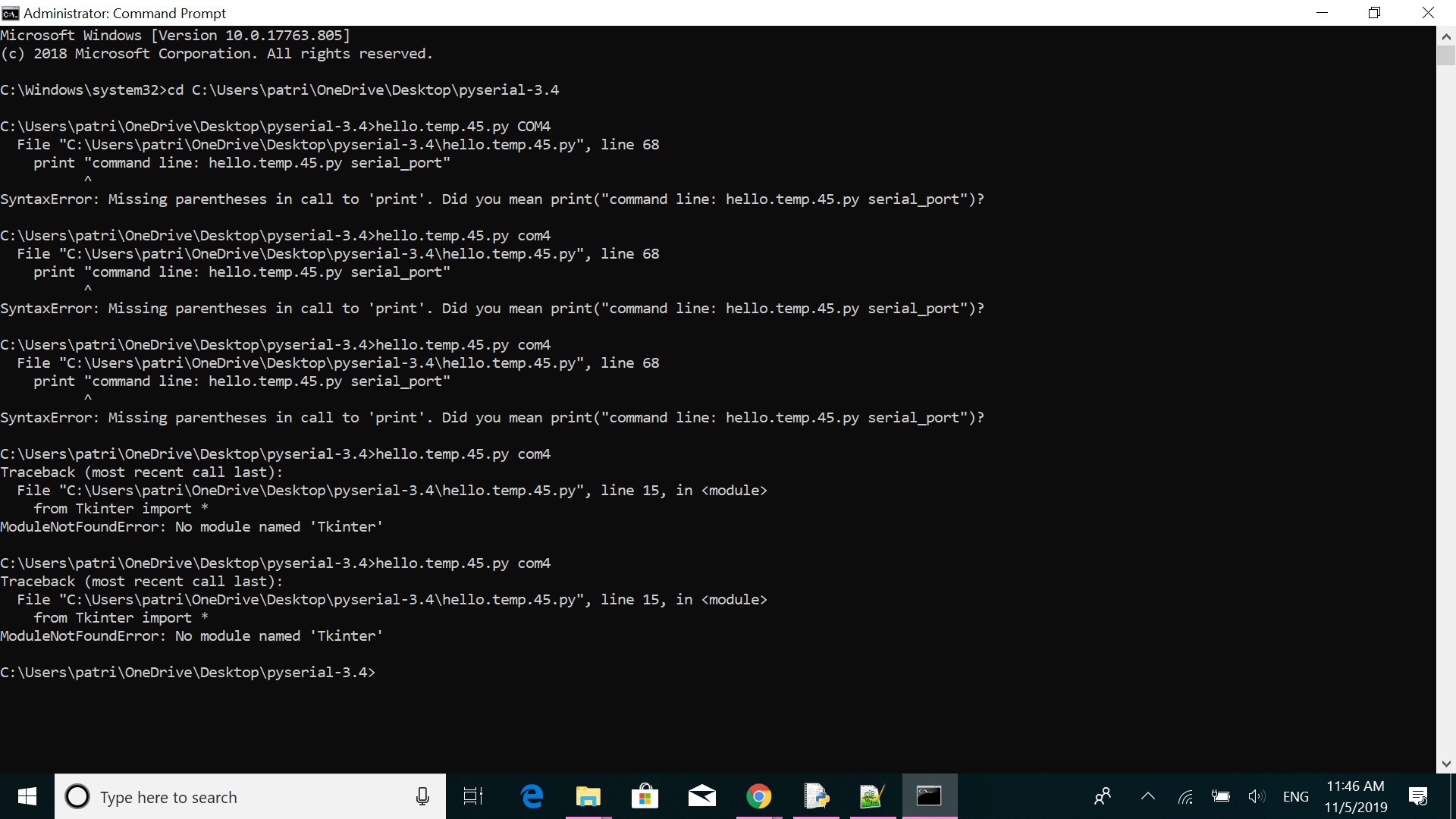
Then, Jiri (thank you soooo much!) told me that I needed the previous Python version in order to run the file and in particular, Python 2.7.17. So, I downloaded Python 2.7.17, set the necessary environmental variables, then installed the pip libraries through the command prompt, add the path to environmental variables, and then install pyserial through the command prompt.

Then, I saved Neil's python file in a specific directory inside my C folder and ran the file through command prompt (run as admin) by going inside this directory and typing the name of the file and the COM port which was in use, i.e. "hello.temp.45.py COM4". And it worked!
I also tested it in water, by submerging the sensor board in a glass of cold water (glass was inside the fridge for 20 mins). I realized that the min temp that could be read by the sensor was 20.33oC and the max temp was 29.82oC. The sensor cannot read/show lower or greater temperatures at the moment, but I'll find a way to fix this...