This week we got a crash-course in CAD work. Neil used FreeCAD as an example to demonstrate parametric design, rendering, animation, and more. Our assignment is to model -- in as many ways we'd like -- a potential final project.
One project idea I have mulled over for some time is constructing an open-source, easy-to-fabricate, sub-milligram analytical balance. These instruments are a critical tool for a wide variety of scientific research and education, but good ones (even on the used market) tend to cost in the thousands of dollars. Also, used scales are gross in a potentially dangerous way depending on their past lives. And despite the proliferation of open science instruments, it doesn't seem like anyone has yet tackled this key device.
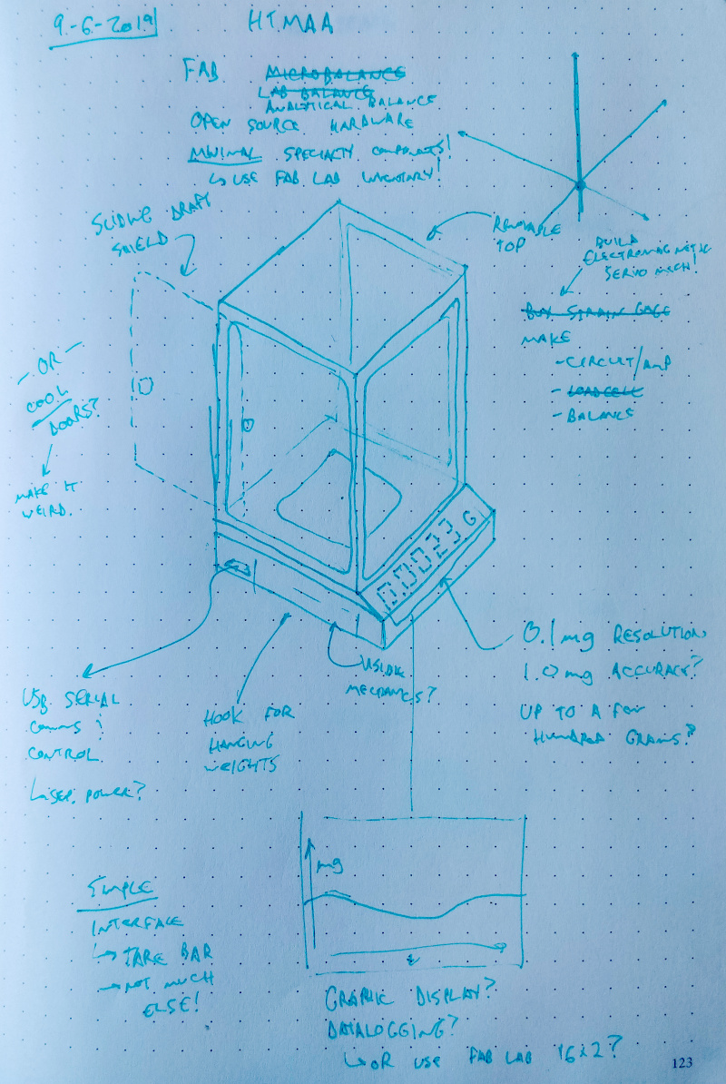
I started by sketching a potential finished balance in my notebook. I particularly like dot paper because it works for flat and isometric sketching:
Translating the notes, because my handwriting isn't the best:
The scale should have an easy-to-use serial port that connects via USB; no special hardware required beyond an FTDI driver. This port is used for scale configuration, datalogging, and remote control.
An analytical balance probably isn't worthwhile if it can't resolve in the 0.1 mg range, with at least +/- 1.0 mg accuracy. Since a 0.1 g scale is part of the standard Fab Lab inventory, it's probably okay if the instrument tops out at <200 g.
One of my favorite undergrad labs involved hanging a lump of copper from an analytical balance and suspending it in an open-top furnace. We were able to plot the copper oxidation rate and learned a great deal about things like passivation, diffusion, and oxide states. This scale needs an easily accessible hook for hanging stuff!
A graphic display is tempting but should be considered a bonus feature; a ubiquitous 16x2 LCD is more than enough for most weighing tasks, and the serial port can handle the rest. The physical user interface should be dead-simple, probably just the display and a big tare bar.
Analytical balances have draft shields. This is one place it could be fun to get weird on the design. Sick lambo doors on a lab instrument? Sounds stupid and awesome.
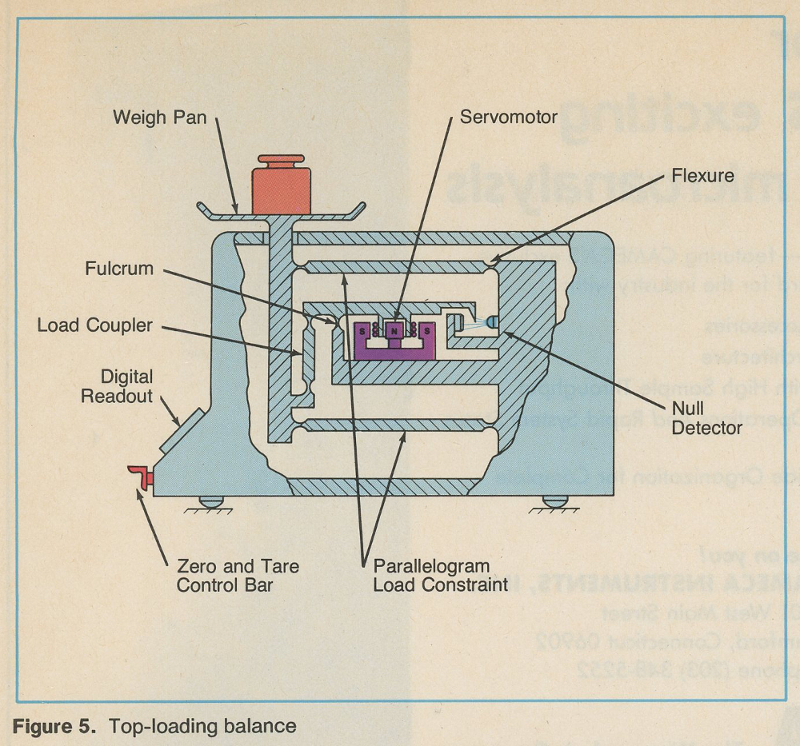
A defining feature of an analytical balance, and what differentiates these instruments from common kitchen scales, is the use of a precision electromagnetic servomechanism. The weighing plate doesn't really move; instead, force is derived by measuring the power required to keep the scale balanced, using an electromagnet and an optical feedback device. Prototyping this part using a Fab Lab-accessible process is at the heart of this project.
model
I used Fusion 360 to explore the core mechanics of the scale:
This hinged mechanism design was inspired by a great 1982 article I found describing the inner workings of analytical balances. Here is the important image from that article, in case the link goes dark:
The program has a handy 'motion study' mode that allows one to animate assemblies without getting down in the weeds. I captured this clip using Windows 10's built-in video capture tool, originally designed for game streaming, and resized/trimmed the file using ffmpeg:
[command: ffmpeg -i motionstudy.mp4 -filter:v "crop=800:1000:500:800" -ss 00:00:02.0 -t 00:00:04.0 -c:a copy out.mp4]
The animation doesn't label the optical feedback mechanism, but you can see the two PCBs (one with an IR LED, one with a phototransistor) to the right of the coil. The NdFeB magnet and armature are mounted to a post in the coil.
prototype
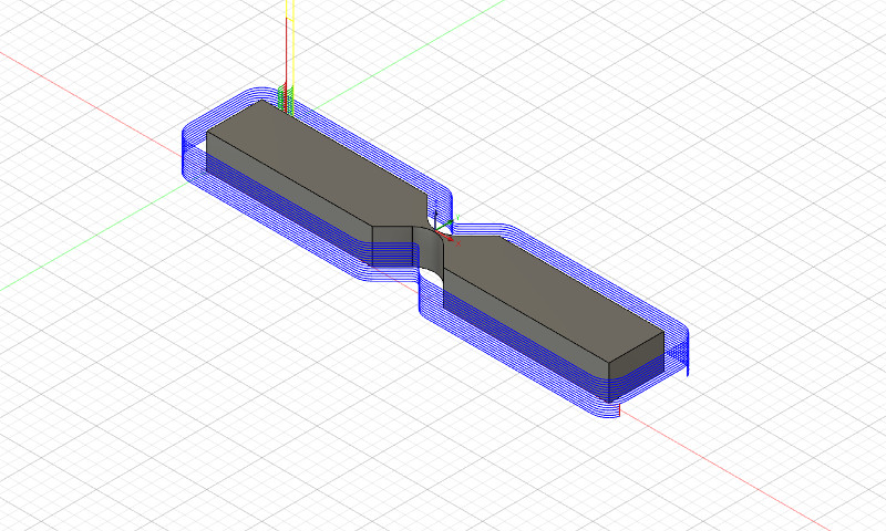
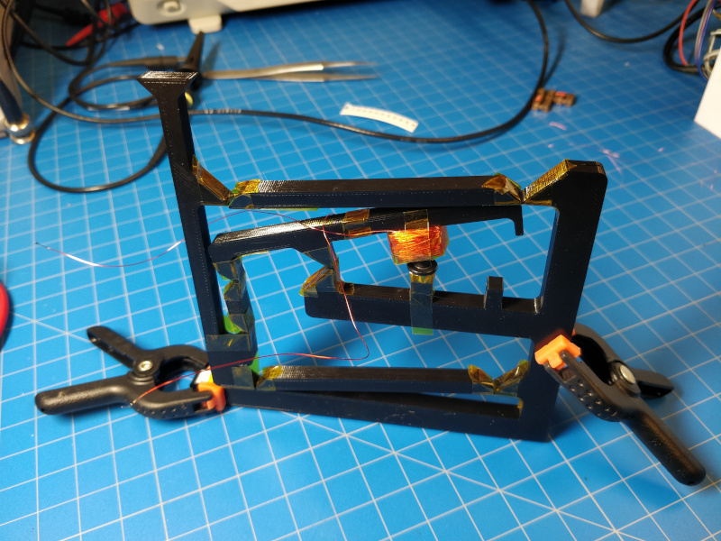
I modeled the mechanism at larger-than-life scale because I needed to test the fabricate-ability of the pin joints as quickly as possible. Initially, I planned to use short lengths of polyamide tape for the hinges, secured to a 3D printed frame and clamped wiht additional 3D printed bits. The Fusion 360-to-Prusa workflow is simple enough that I printed the model without much trouble, using the Prusa default settings and black PLA:
The motion worked as expected, mirroring the Fusion 360 motion study. However, I didn't try to clamp the polyamide tape to the 3D printed beams, and after a few actuations the tape delaminated enough to cause significant off-axis motion. Before this occured, I powered the electromagnet using a bench scale and found it to require approximately 1.65 VDC at 0.8 A at steady state. Note that the mechanism exhibited sufficient hysteresis that without the optical feedback it was impossible to actually hold the scale at the midpoint. The coil got warm but not uncomfortably hot during these experiments.
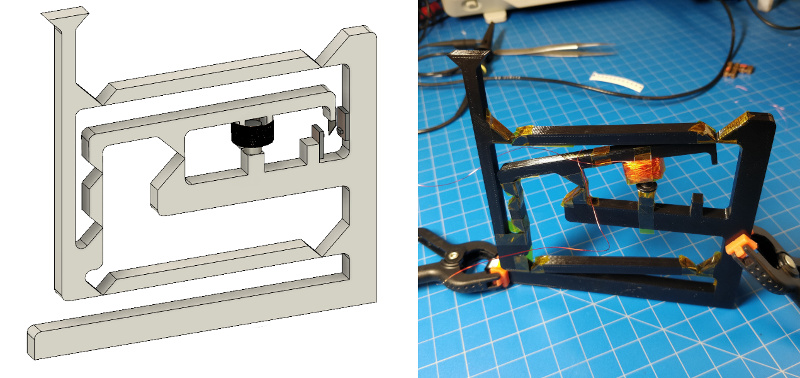
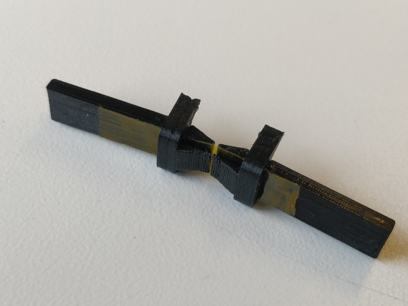
For the next prototype, I focused on redesigning the polyamide hinge to prevent delamination. I came up with a simple snap clip that pinched the tape near the flexure:
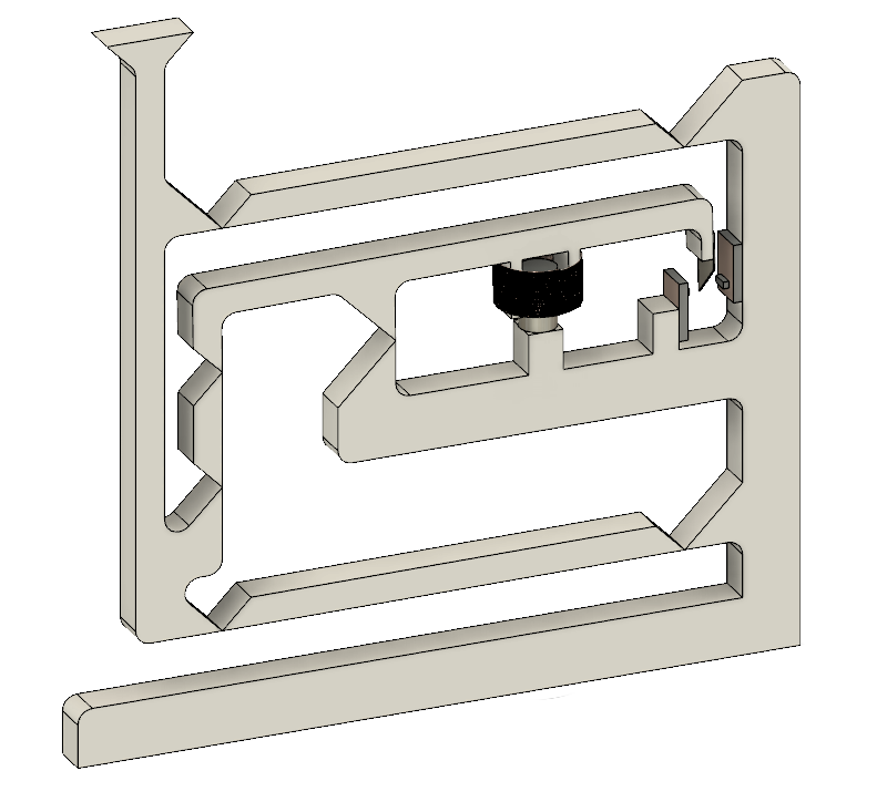
Dialing in the clip tolerance took a number of iterations but the parts were small enough that they only took a few minutes to print, making the process quite efficient. Assembled:
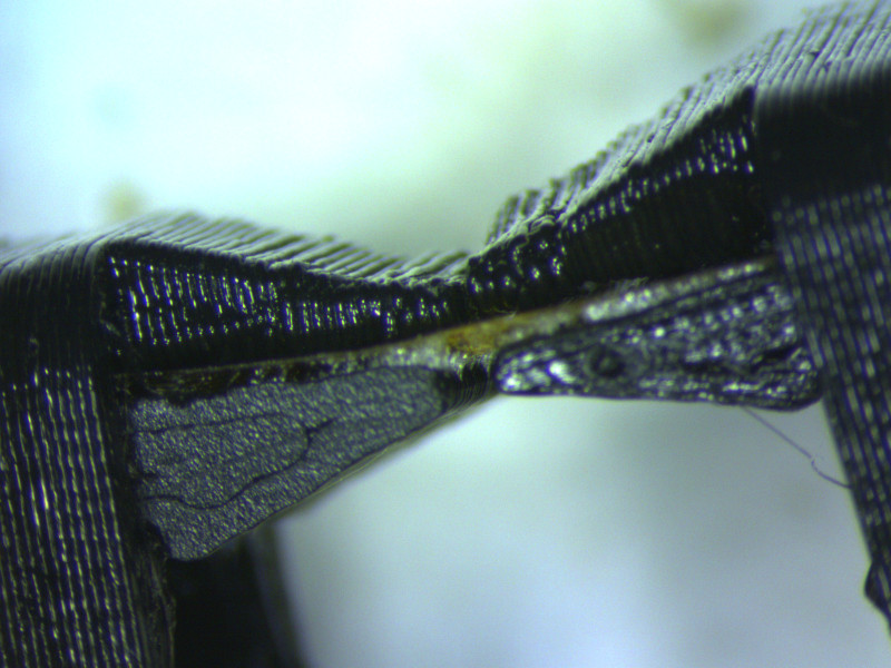
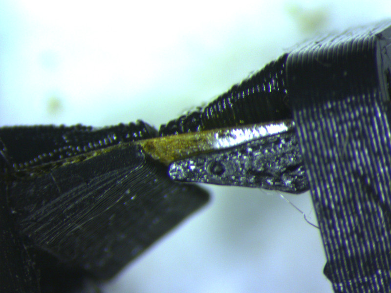
However, after a few actuations the joint started exhibiting the same off-axis play as the original model. A close-up revealed the problem to be delamination:
Another noteable concern with this design is the limited 'sharpness' of the 3D printed parts adjacent to the flexure. Compared with the model, the FDM print had a significant unwanted corner radius that prevented the beams from being close enough to approximate a pin joint; even before delamination, the joint allowed enough shear to introduce signicant uncertainty into the mechanism.
next steps
I want to try machining a living hinge out of acetal sheet. I plan to start with a few test coupons to dial in the hinge thickness, and then mill the whole hinge mechanism out of a single piece. This will allow me to further miniaturize the mechanism, and will reduce the laborious and error-prone assembly process. Acetal (or Delrin) is a common but somewhat expensive polymer that is highly suited to machining and laser cutting, and is known for its toughness. This iteration may wait for Week 06, which focuses on CNC milling.
 This week we got a crash-course in CAD work. Neil used FreeCAD as an example to demonstrate parametric design, rendering, animation, and more. Our assignment is to model -- in as many ways we'd like -- a potential final project.
One project idea I have mulled over for some time is constructing an open-source, easy-to-fabricate, sub-milligram analytical balance. These instruments are a critical tool for a wide variety of scientific research and education, but good ones (even on the used market) tend to cost in the thousands of dollars. Also, used scales are gross in a potentially dangerous way depending on their past lives. And despite the proliferation of open science instruments, it doesn't seem like anyone has yet tackled this key device.
This week we got a crash-course in CAD work. Neil used FreeCAD as an example to demonstrate parametric design, rendering, animation, and more. Our assignment is to model -- in as many ways we'd like -- a potential final project.
One project idea I have mulled over for some time is constructing an open-source, easy-to-fabricate, sub-milligram analytical balance. These instruments are a critical tool for a wide variety of scientific research and education, but good ones (even on the used market) tend to cost in the thousands of dollars. Also, used scales are gross in a potentially dangerous way depending on their past lives. And despite the proliferation of open science instruments, it doesn't seem like anyone has yet tackled this key device.
 Translating the notes, because my handwriting isn't the best:
 This hinged mechanism design was inspired by a great 1982 article I found describing the inner workings of analytical balances. Here is the important image from that article, in case the link goes dark:
 The program has a handy 'motion study' mode that allows one to animate assemblies without getting down in the weeds. I captured this clip using Windows 10's built-in video capture tool, originally designed for game streaming, and resized/trimmed the file using ffmpeg:
[command: ffmpeg -i motionstudy.mp4 -filter:v "crop=800:1000:500:800" -ss 00:00:02.0 -t 00:00:04.0 -c:a copy out.mp4]
The animation doesn't label the optical feedback mechanism, but you can see the two PCBs (one with an IR LED, one with a phototransistor) to the right of the coil. The NdFeB magnet and armature are mounted to a post in the coil.
The program has a handy 'motion study' mode that allows one to animate assemblies without getting down in the weeds. I captured this clip using Windows 10's built-in video capture tool, originally designed for game streaming, and resized/trimmed the file using ffmpeg:
[command: ffmpeg -i motionstudy.mp4 -filter:v "crop=800:1000:500:800" -ss 00:00:02.0 -t 00:00:04.0 -c:a copy out.mp4]
The animation doesn't label the optical feedback mechanism, but you can see the two PCBs (one with an IR LED, one with a phototransistor) to the right of the coil. The NdFeB magnet and armature are mounted to a post in the coil.
 The motion worked as expected, mirroring the Fusion 360 motion study. However, I didn't try to clamp the polyamide tape to the 3D printed beams, and after a few actuations the tape delaminated enough to cause significant off-axis motion. Before this occured, I powered the electromagnet using a bench scale and found it to require approximately 1.65 VDC at 0.8 A at steady state. Note that the mechanism exhibited sufficient hysteresis that without the optical feedback it was impossible to actually hold the scale at the midpoint. The coil got warm but not uncomfortably hot during these experiments.
For the next prototype, I focused on redesigning the polyamide hinge to prevent delamination. I came up with a simple snap clip that pinched the tape near the flexure:
The motion worked as expected, mirroring the Fusion 360 motion study. However, I didn't try to clamp the polyamide tape to the 3D printed beams, and after a few actuations the tape delaminated enough to cause significant off-axis motion. Before this occured, I powered the electromagnet using a bench scale and found it to require approximately 1.65 VDC at 0.8 A at steady state. Note that the mechanism exhibited sufficient hysteresis that without the optical feedback it was impossible to actually hold the scale at the midpoint. The coil got warm but not uncomfortably hot during these experiments.
For the next prototype, I focused on redesigning the polyamide hinge to prevent delamination. I came up with a simple snap clip that pinched the tape near the flexure:
 Dialing in the clip tolerance took a number of iterations but the parts were small enough that they only took a few minutes to print, making the process quite efficient. Assembled:
 However, after a few actuations the joint started exhibiting the same off-axis play as the original model. A close-up revealed the problem to be delamination:
 Another noteable concern with this design is the limited 'sharpness' of the 3D printed parts adjacent to the flexure. Compared with the model, the FDM print had a significant unwanted corner radius that prevented the beams from being close enough to approximate a pin joint; even before delamination, the joint allowed enough shear to introduce signicant uncertainty into the mechanism.