WEEK10: output devices
 This week we learned about electronic output devices. This category includes optoelectronics, such as LEDs and displays; audibles, such as speakers; and motion systems, such as motors and other actuators. A differentiator from input devices is the fact that many outputs require higher currents than a microcontroller can source or sink, so we also learned about MOSFETs and other types of electronic switches. We spent a decent bit of time on different types of motors -- steppers, servos, DC, brushless -- since they will play a key role in future classes (such as Machine Week). Our assignment this week was twofold: first, use test equipment to characterize the current consumption of an output device; and second, add an output device to a microcontroller board we designed.
files
- actuator model STEP format and Fusion 360 format
- actuator calculation spreadsheet
dc motor characterization
Sabrina, Alfonso, Patricia, Aubrey, and I met shortly after class to characterize the current consumption of a DC motor. I rigged up a DC gear motor to my bench power supply through a high-wattage shunt resistor, and we measured the motor supply voltage and sense resistor voltage drop at various loads. Here is an image of our setup, showing shunt resistance voltage drop (top) and power supply (bottom) on the test instruments: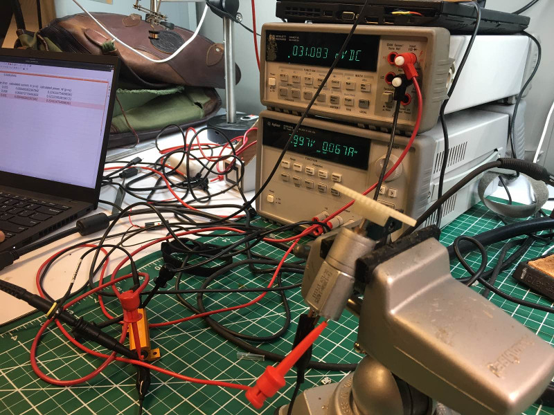 The shunt resistance measured 0.549 ohms; current through the circuit was measured by dividing supply voltage by this value according to Ohm's law (V=IR). Power through the motor was calculated by multiplying the circuit current by the motor voltage, which was calculated as supply voltage minus resistor voltage drop. Results:
| supply voltage, V | resistor voltage drop, V | calculated current, A | motor power, W |
|---|---|---|---|
| 4.00 | 0.031 | 0.056 | 0.224 |
| 8.00 | 0.036 | 0.066 | 0.522 |
| 4.00 | 0.25 | 0.455 | 1.708 |
| 4.00 | 0.61 | 1.111 | 3.767 |
langford-style voice coil actuator
Will Langford is a former CBA PhD student that graduated a few months ago. During his time in the lab, he developed a high power density linear voice coil actuator for his tiny assembled robots. You can read a good deal more about the project in his thesis; in particular, check out Chapter 5, Actuation. Actually, you should just read the whole thing; his thesis is full of fascinating antecdotes and clever solutions to difficult problems. As part of my final project, I need a linear electromagnetic actuator that can offset a few dozen grams on the balance without heating up too much. The actuator should be compact, easy to fabricate, and highly repeatable, with minimal static friction to ensure maximum scale sensistivity on the low end. After a few poorly planned attempts to wind coils earlier this semester, I decided to try duplicating his work for my application.building
I manufactured my actuator in a similar manner to Will. The assembly has two major components: a magnetic part, which is made of high permeability steel with a few rare earth magnets glued on, and a mandrel, made of phenolic with wound coil. I started with a simple parametric model in Fusion 360 to get a feel for sizing, using material on hand: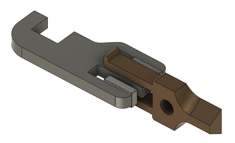 I cut the magnetic part on the wire-EDM. This is a fascinating machine I have been learning to operate over the last few weeks; it uses a hair-thin brass wire and a plasma to slowly erode conductive material, combined with a precision XY stage to advance the wire through the part. The entire work area is submerged in deionized water, and a high pressure jet runs along the wire to flush cut material debris out of the gap. There isn't much to see beyond a few bubbles while the part is being cut:
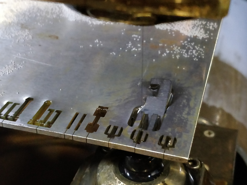
... but the machine's tensioning system provides plenty of visual interest as it advances the wire:
After cutting, the part popped out for collection. Since the machine doesn't produce any slag or draft, there is no finishing work required:
I cut the magnetic part on the wire-EDM. This is a fascinating machine I have been learning to operate over the last few weeks; it uses a hair-thin brass wire and a plasma to slowly erode conductive material, combined with a precision XY stage to advance the wire through the part. The entire work area is submerged in deionized water, and a high pressure jet runs along the wire to flush cut material debris out of the gap. There isn't much to see beyond a few bubbles while the part is being cut:
... but the machine's tensioning system provides plenty of visual interest as it advances the wire:
After cutting, the part popped out for collection. Since the machine doesn't produce any slag or draft, there is no finishing work required:
 The mandrel milled nicely on the MDX-540; the process produces fine dust, so the vacuum is important here:
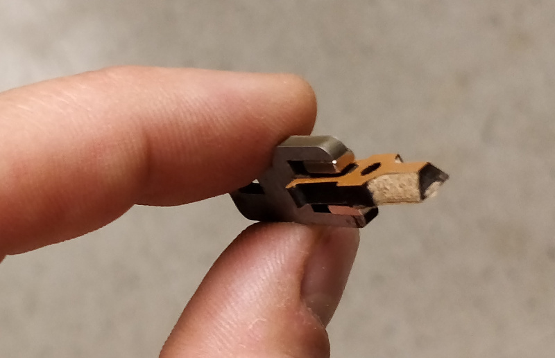
A quick fit check suggests we're on the right track; note the triangular end, designed to fit in the Jacob's chuck of the coil winder:
The mandrel milled nicely on the MDX-540; the process produces fine dust, so the vacuum is important here:
A quick fit check suggests we're on the right track; note the triangular end, designed to fit in the Jacob's chuck of the coil winder:
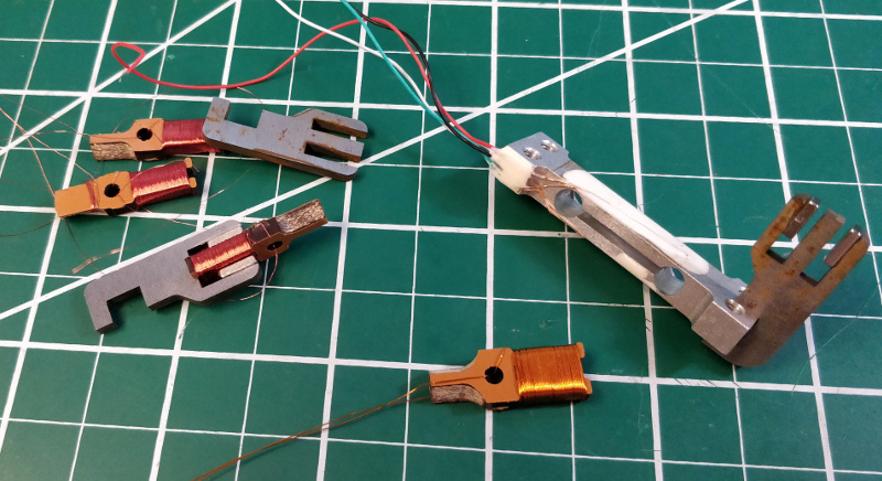
 I used CBA's coil winder to spin a bit of 40 AWG wire on the coil; later, I backed this off to 34 AWG to improve thermal performance at higher currents. This machine has a foot pedal speed control and a few simple limit stops, and is a pleasure to use:
One unexpected issue that required a few EDM and mill iterations to solve was the fact that the wire tension caused the mandrel to deform slightly, preventing it from fitting on the magnet part. I tweaked parameters a few times, and eventually beefed up the mandrel a bit too:
I used CBA's coil winder to spin a bit of 40 AWG wire on the coil; later, I backed this off to 34 AWG to improve thermal performance at higher currents. This machine has a foot pedal speed control and a few simple limit stops, and is a pleasure to use:
One unexpected issue that required a few EDM and mill iterations to solve was the fact that the wire tension caused the mandrel to deform slightly, preventing it from fitting on the magnet part. I tweaked parameters a few times, and eventually beefed up the mandrel a bit too:
testing
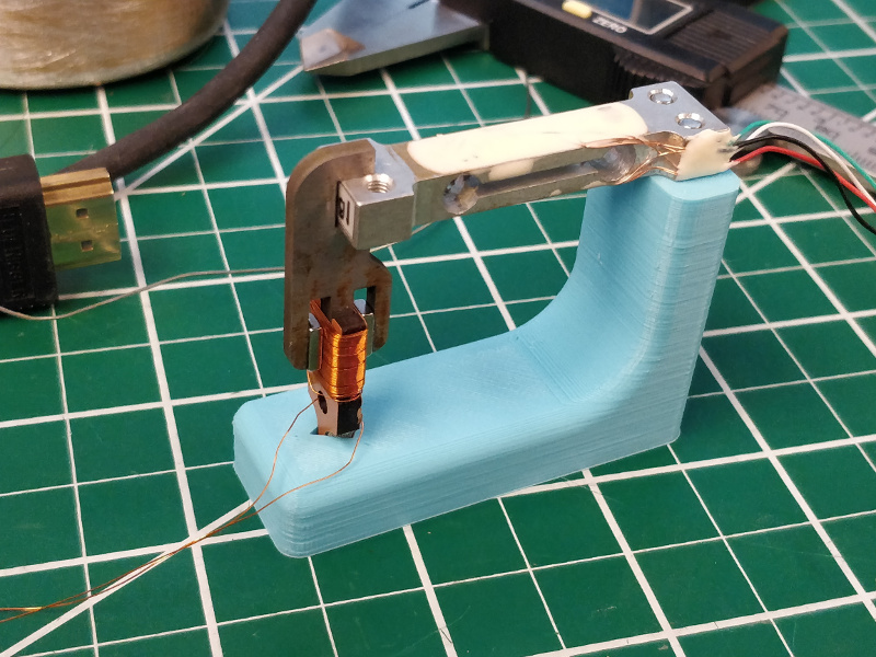
Will spent a good amount of time simulating and testing his actuator design. Since I copied his geometry, I was able to lean heavily on the numerical model he produced to estimate force from the actuator as a function of current. Again, I suggest reading Chapter 5 of his thesis if you want to learn more; briefly, one can estimate the force from the actuator as F = N * I * B * L, where F is the force in newtons; N is the number of turns in the coil; I is the coil current in amps; B is the magnetic flux density in the air gap; and L is the length each coil has to interact with the permenant magnets. B is further calculated from the coil air gap width and area, and the permanent magnet thickness and area. Plugging in the measurements from my actuator, the model suggests I should see a force in the range of 283 mN at 0.6 A. This value is further multiplied by a loss coefficient n. See files for the complete data set. To validate the model, I designed and 3D printed a simple frame to hold a 100g load cell along with the actuator assembly:
Prior to installing the actuator, I calibrated the load cell with a set of precision weights and found its response at 5.01 VDC excitation to be 61.011 grams per volt. Then I installed the actuator and increased the current through the device in 100 mA increments; note the load cell output (center meter) changing as I do this:
The results, after converting load cell mV to g and g to N, were encouragingly linear across the whole range:
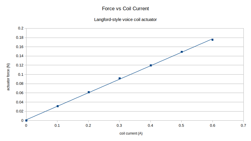 Will's actuator was pretty close to the theoretical calculations. Mine, on the other hand, had a loss coefficient of 0.62. Oh well, it should work well enough for the scale; losses will just cause extra heating. Speaking of which, during the test, I used our FLIR i5 to capture a thermography image of the coil at 0.5 A after the temperature stabilized, showing a peak temp of 78 C:
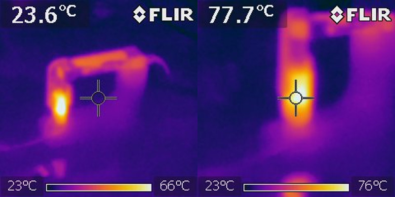 Probably on the upper end of what I want inside a precision scale chassis, but the phenolic and coil insulation can handle this temperature without any issues. In any case, assuming a 1:2 lever arm ratio between the voice coil actuator and the scale tray, this suggests an upper measurement range in the 30g range for the scale.