CAD is the process of taking objects in your imagination and properly defining them enough for a machine to make them. Popular software for this includes SolidWorks, Autodesk Fusion, FreeCAD, and OnShape. For this tutorial, I'll just cover some of the points of OnShape.
OnShape is an online platform for CAD. It is free for students. You can sign up by requesting the the Education Plan.
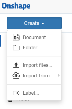
https://www.onshape.com/sign-upThe first step is creating a new document using the dropdown on the top left. You can also create folders to keep files organized. I highly recommend using a mouse instead of a trackpad.
From there, most designs start with a sketch. Sketches are 2D drawings and need to be done on a plane. For your first sketch, you should pick one of the default planes: Top, Front, or Right. For later sketches, you can also use the faces of objects as planes for sketching. You can select the plane by clicking it in the 3D view on the right or by clicking it in the list on the left.


With the sketch menu open, you can edit the sketch. You can adjust the view by clicking on the cube and the controls to the top right. You can also right click on components in the left menu and select "View normal to" to get a face on view. Note that you'll need to close the sketch to do that. You can also right click and drag to orbit around. You can also turn off objects you don't want to see by mousing over them and clicking the eye icon in the left menu. If you need to zoom in or out, you can use the mouse wheel. You can pan without rotating by holding down the mouse wheel.


Once you have your sketch open and properly oriented, we can start adding elements to it. There are a lot of options here, so I'll just list some of the common options. Different elements like lines, rectangles, circles, arcs, polygons, splines, and points can be added using the options on the top left. These will define the basic components of your sketch. Note that you can add construction lines and objects using the construction option. Those objects can be used to help define your sketch, but will not appear in the final sketch. That option can also be used to toggle the construction status of selected objects. Note that certain critical points will often be snapped to existing objects. You can avoid that by creating the objects in a different location or size and dragging them over to adjust.


Once you have your elements added, they need to be constrained. Even if the sketch looks right, none of the proportions or locations are fixed. For qualities inherent to the object like squares having equal sides, you can use the constraints in the dropdown on the top center. Those can do things like setting lengths equal and making lines parallel or perpendicular. For qualities which are not inherently defined like lengths and radii, you can set the values using the dimension tool. That allows you to set values like lengths, diameters, distances between lines, and angles between lines.


Beyond the basic tools, there are a bunch of advanced options. I'll just cover a couple here. The trim and extend tools can modify lines to clean up your drawing. You can also use the fillet tool to round out corners. You can also set the radius of the fillet. Be careful with these tools because they can make unexpected changes to your sketch. In particular, lines can be shortened or changes, so your old constraints and dimensions may be broken.


In the course of constraining your sketch, you will probably have to attach something to the origin. It can be more convenient to attach the bottom or the center of your sketch depending on what you need later on. A reasonable way to check if everything is properly defined is by looking for light blue elements. Those elements have some freedom to move. By using a left click to drag those elements around, you can see what features are not fully defined. You can use Ctrl+Z to undo any damage you do.
Once your design is finished, you can export the sketches and the parts. Since OnShape's versioning is somewhat questionable, it can be difficult to recover older versions. Exporting versions as you go can be a good way to save older versions.
Sketches can be exported by right clicking on the sketch and selecting "Export to DXF/DWG". OnShape supports exporting to .dxf and .dwg files. I've had good luck with the default settings for .dxf files.


3D parts can be exported by right clicking on the Part Studio tab and selecting "Export...". You can also select particular parts for exporting by left clicking them in the left menu. OnShape supports many of the standard formats for 3D objects. It has occasionally mangles .stl's, so you should double check the exported files. I've had good luck with .stl's for 3D printing. You might need to switch between exporting in inch or mm scale depending on what's using the files. For importing to SolidWorks, use the SOLIDWORKS option. For importing to Fusion, use the STEP option.


You can add parameters using the configurations feature. Once the variable has been added, you can define values in your sketch by using the identifiers for the parameters which start with a hash (#). Although models will resize when the parameters change, different parts of the model may not be fully constrained or anchored as intended. Be sure to check you model after you change the parameter to ensure it is still as you expected.