Week 10: Networking and Communications
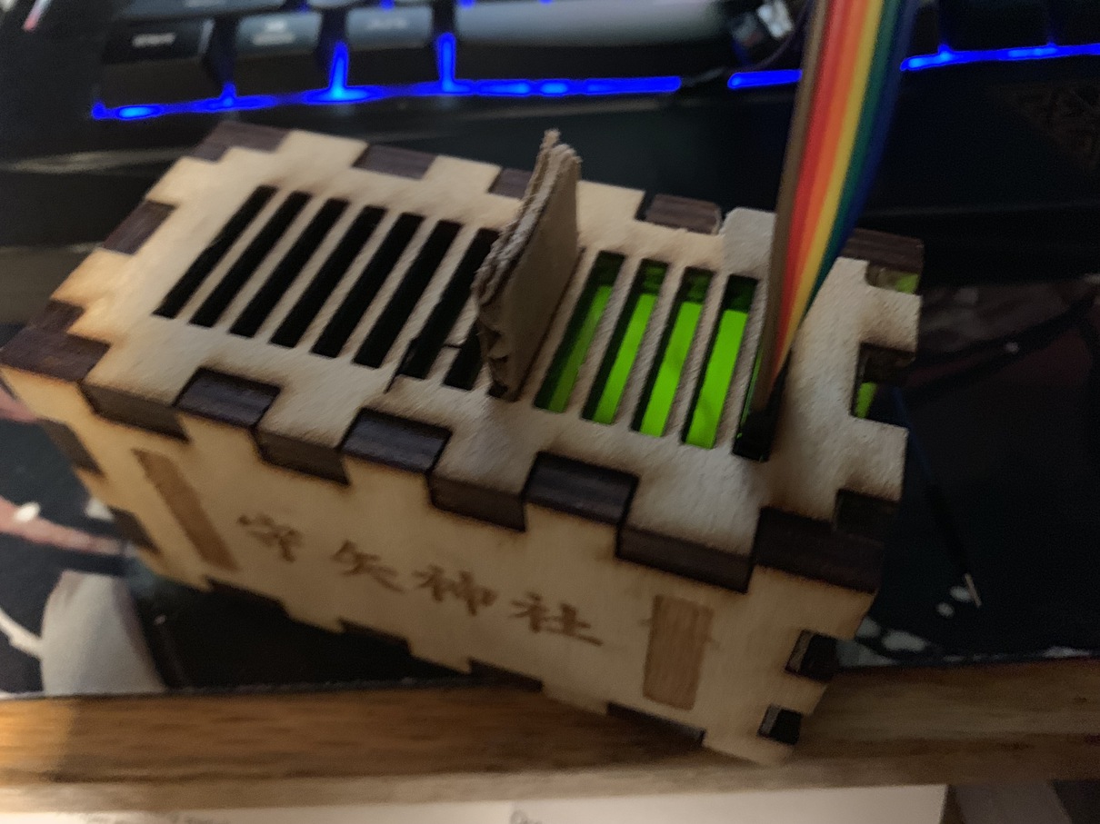
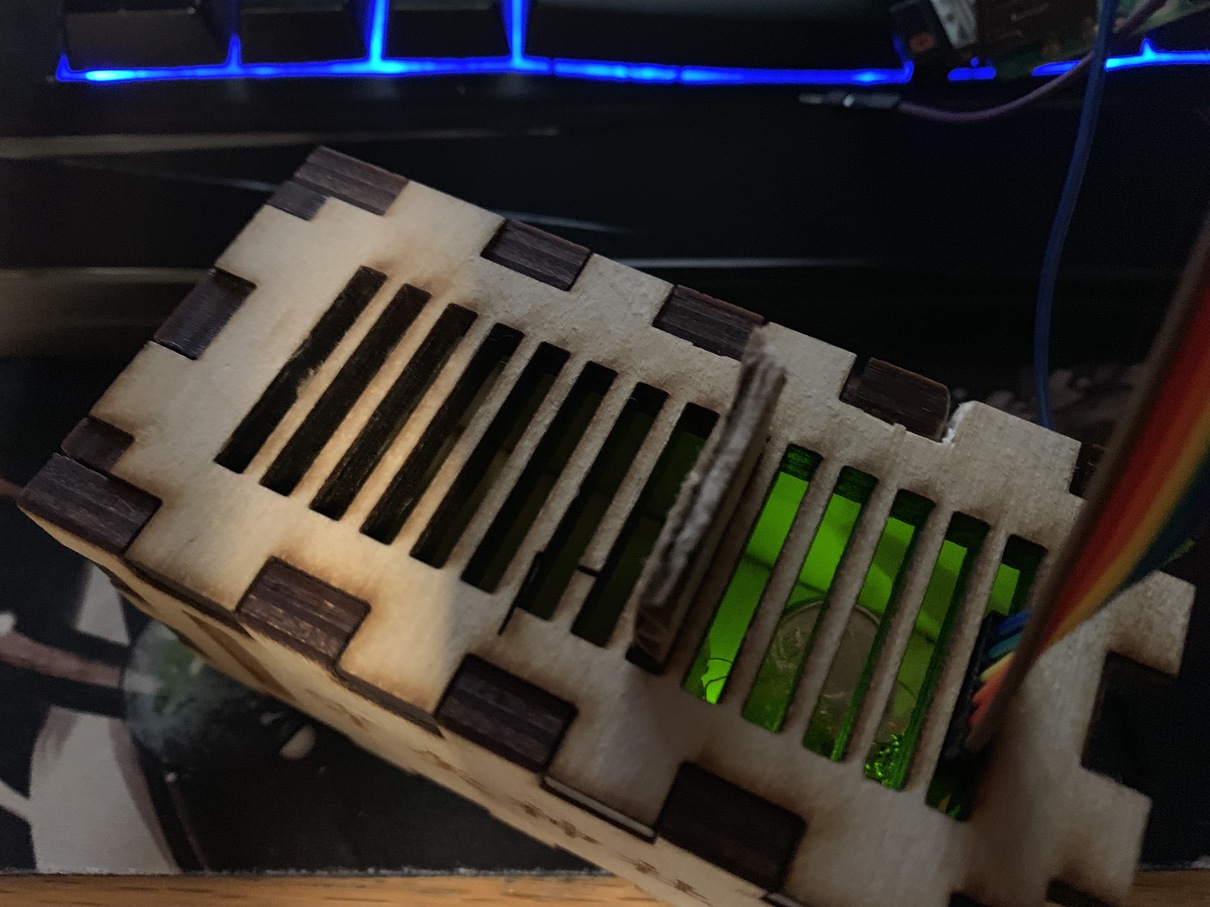
This week, I wanted to learn the ins and outs of serial communication, by hooking up the donation box sensor to a Raspberry Pi purely through the GPIO pins. In the past, I've been using an FTDI adapter, which basically lets us connect the six-pin pinout on these various boards to a USB port on any computer, which can then read serial out as 'usbserial'. The great thing about the Raspberry Pi, however, is that it can actually read the voltages directly through its GPIO pins, so I ideally don't an FTDI adapter at all.
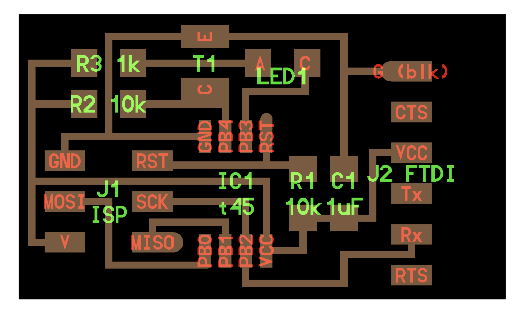
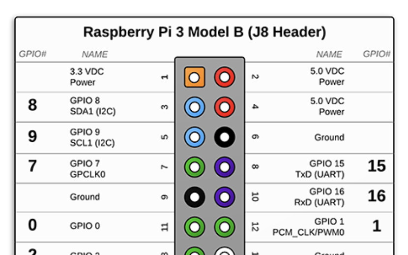
The first thing to do is figure out how to wire the pins. Looking at the board design for the light detector, there are six pinouts: ground, CTS, VCC, Tx, Rx, and RTS. It turns out that each of these serves a very specific purpose. Ground and VCC serve to power the board, with ground connecting to the ground port of the Pi, and VCC connecting to the 5v port. It is actually possible to use 3.3v instead, but it makes the LED on the board a lot dimmer so I tried to use 5v as much as I could. The other important pins are Rx and Tx. These are used for serial connection -- one is for reading, and one is for writing. Basically, the device that is writing over serial will send information over a pre-determined baud rate, 9600 in our case. This gets translated into a sequence of voltage high and voltage lows, encoding the information in binary to send it to the other device. The light board and the Pi both have a pin for writing and a pin for reading, and although I only need to communicate one way I decided to hook them both up anyways.
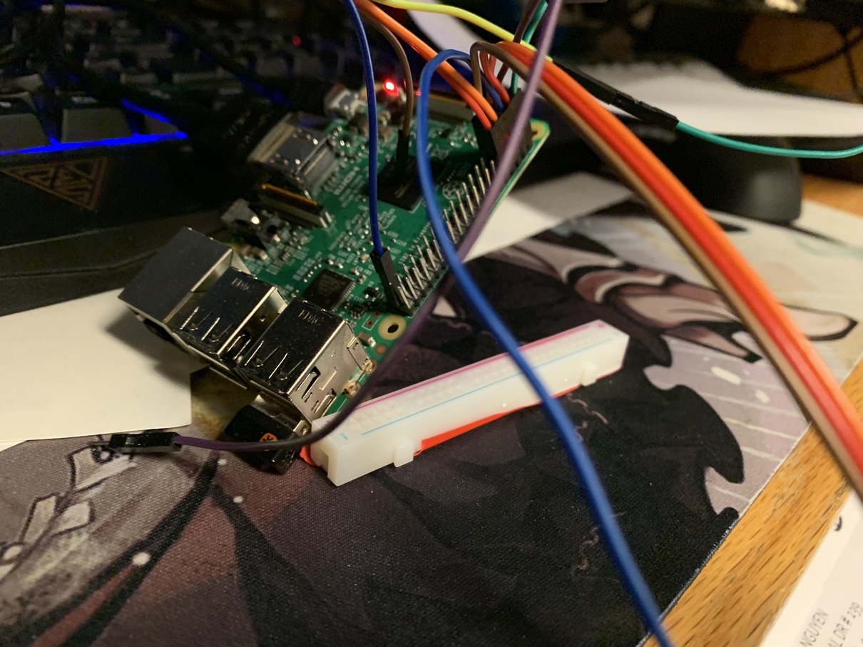
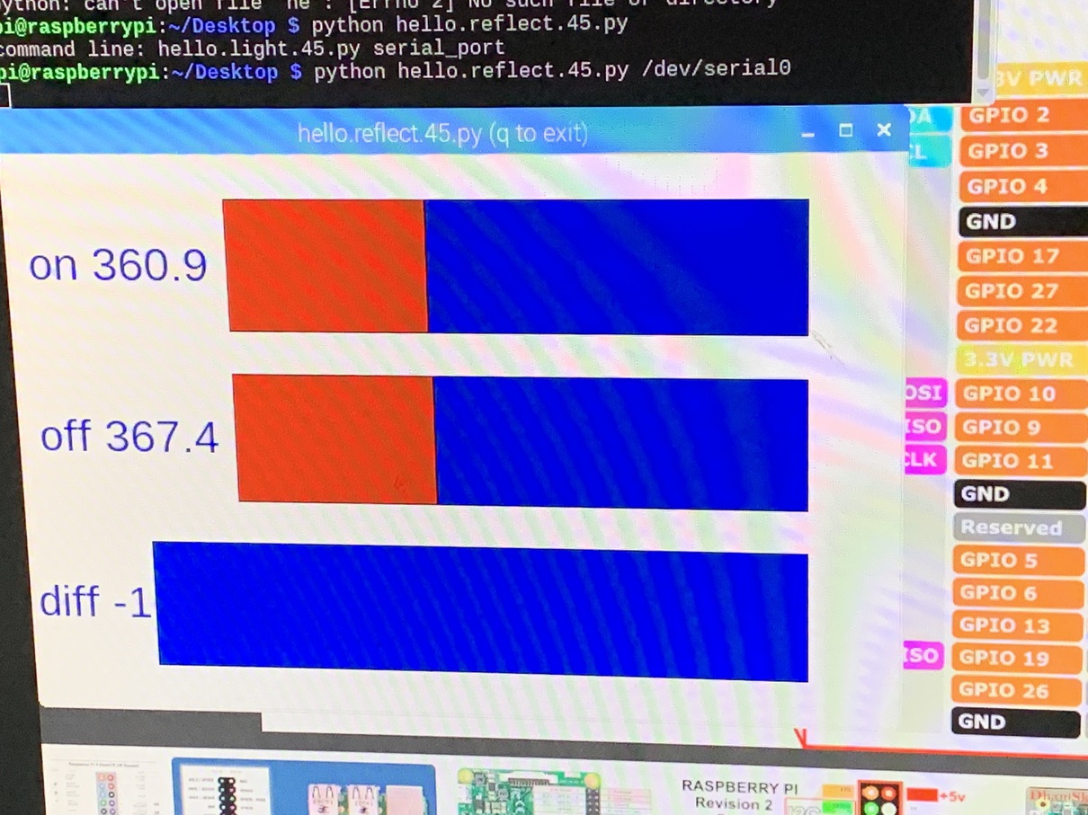
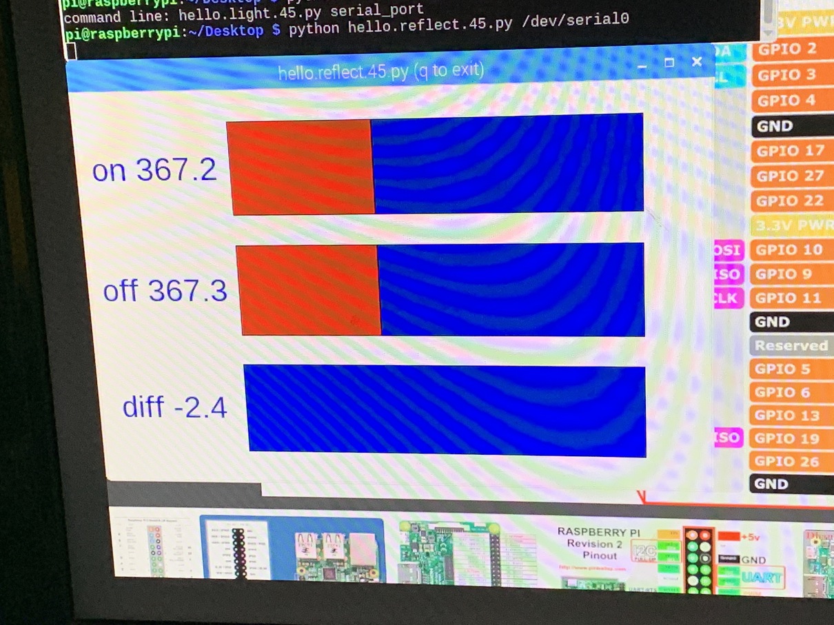
When I first connected the pins together, there was a lot of troubleshooting to do. The raspberry pi refused to read any information from the pin. The especially annoying thing here is that since we're reading directly through the GPIO pins, we don't get any fancy debugging information like usb. When using usberial and the FTDI cables, it is easy to check if the cimputer recognizes the device by seeing if a usbserial device is shown on the device list. But for the GPIO pins, if there is no connection, it simply shows up as no information being sent. After a bit of trial and error, I found out that the issue was I had mixed up Rx and Tx, so the board and the Pi were both trying to read from the same pin and write to the same pin. So of course the Pi would read nothing. After switching up the two, the boards were finally able to connect!
Finally, I want to do a bit of discussion on how the serial communication actually works.
    // framing
    put_char(&serial_port, serial_pin_out, 1);
    char_delay();
    put_char(&serial_port, serial_pin_out, 2);
    char_delay();
    put_char(&serial_port, serial_pin_out, 3);
    char_delay();
    put_char(&serial_port, serial_pin_out, 4);
    char_delay();
    //
    // send result
    //
    put_char(&serial_port, serial_pin_out, (on & 255));
    char_delay();
    put_char(&serial_port, serial_pin_out, ((on >> 8) & 255));
    char_delay();
    put_char(&serial_port, serial_pin_out, (off & 255));
    char_delay();
    put_char(&serial_port, serial_pin_out, ((off >> 8) & 255));
    char_delay();
    #
    # find framing
    #
    while 1:
        byte1 = byte2
        byte2 = byte3
        byte3 = byte4
        byte4 = ord(ser.read())
        if ((byte1 == 1) & (byte2 == 2) & (byte3 == 3) & (byte4 == 4)):
        break
    on_low = ord(ser.read())
    on_high = ord(ser.read())