Week 9: Output Devices
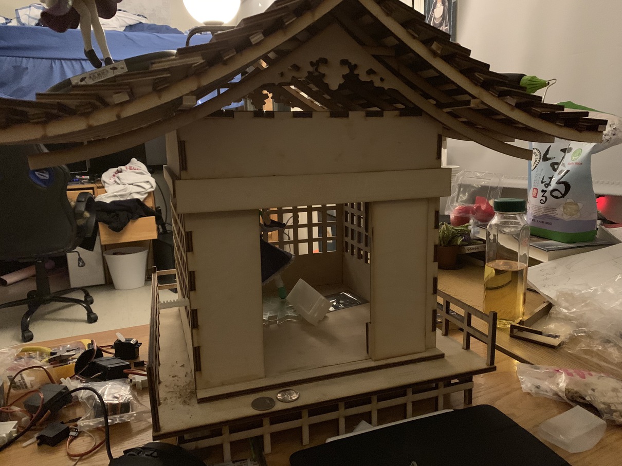
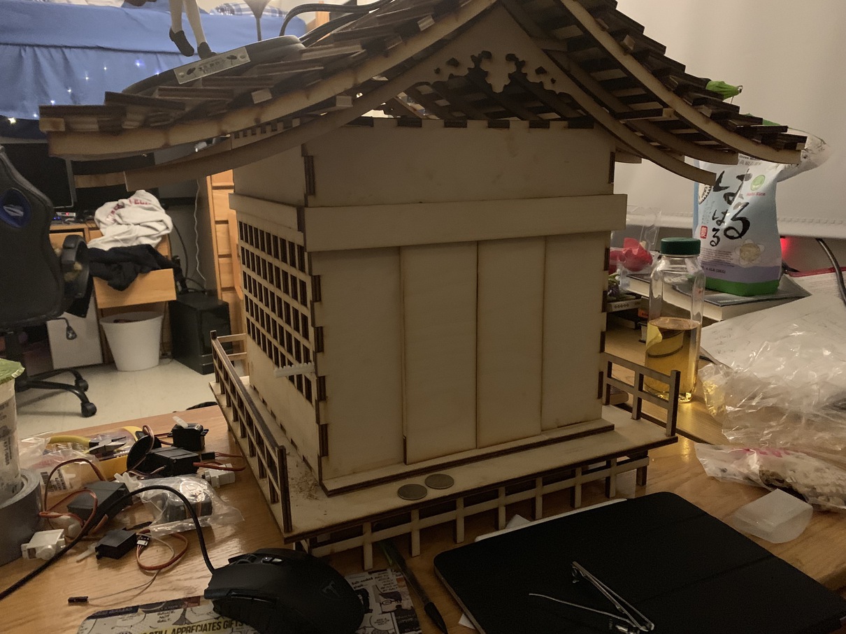
Work on the motorized shrine continues! This episode, we work on the mechanism for opening and closing the doors. Again, I had already built the doors and the shrine opening out of laser-cut wood, so this would be a challenge in engineering a mechanism small enough to be super obvious, but with enough power and reach to open the doors on demand. Above is the shrine itself, with the doors in open and closed position.
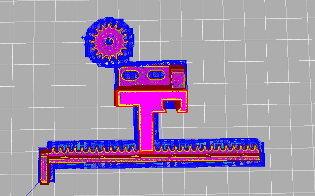
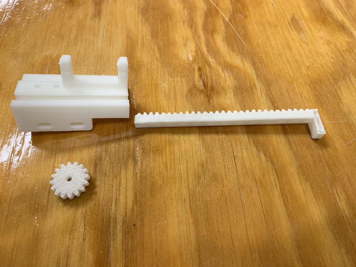
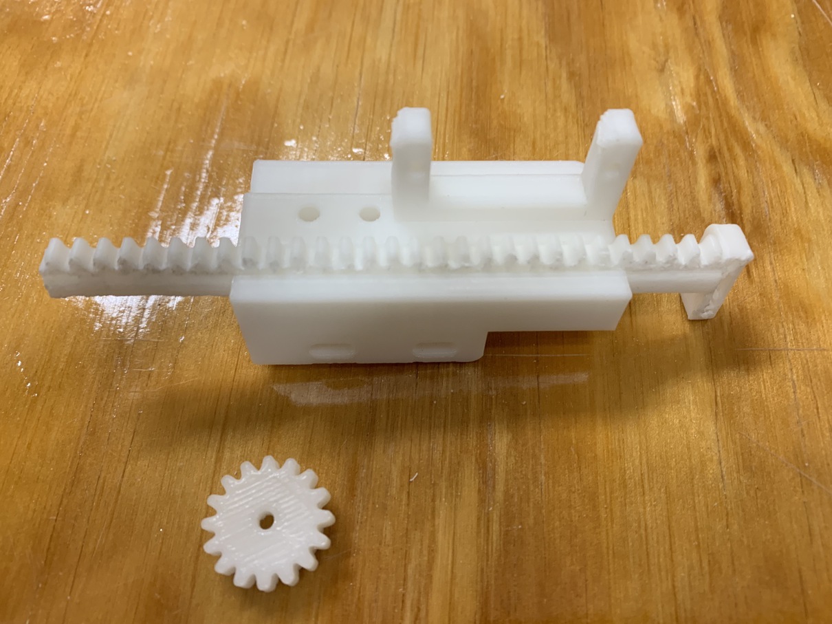
The first challenge was how to achieve linear motion. As it turns out, servos and motors are easy to achieve, but moving things in along a straight rather than singular axis is a bit tricky. My attempt uses a rack-and-pinion design that uses a single gear to push a small stick with ridges along a gap.
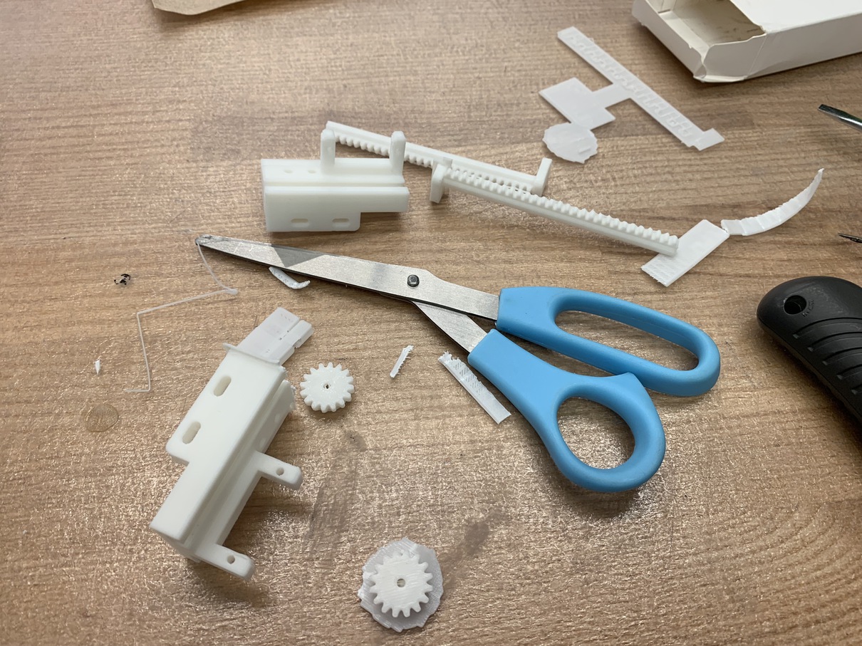
When the prints first came out, there was a lot of supporting material that became extremely hard, and was basically impossible to remove by hand. This was a big problem, since the rod had to fit perfectly in the gap for the mechanism to move smoothly. I had to use a knife and a pair of pliers to remove all the extra material, along with a few rounds of sanding, before the rod could slide through.
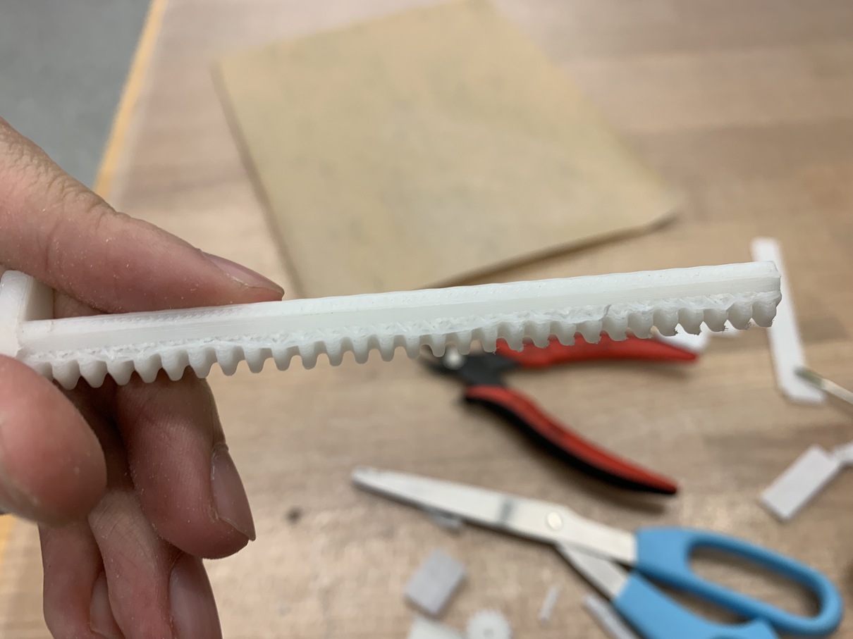
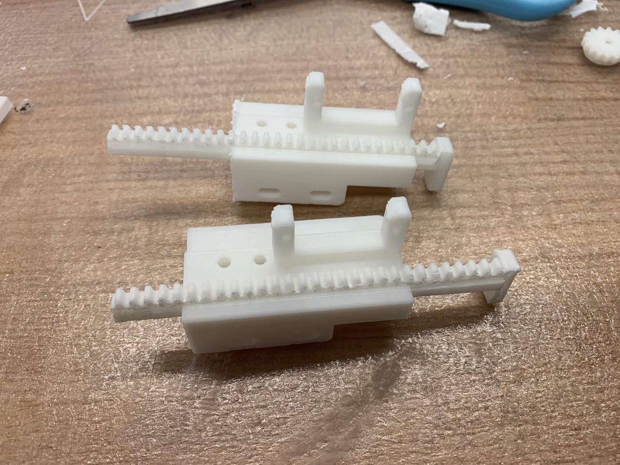
After many hours of sanding and chiseling, the rack moves smoothly!!!
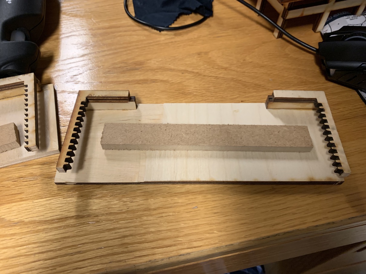
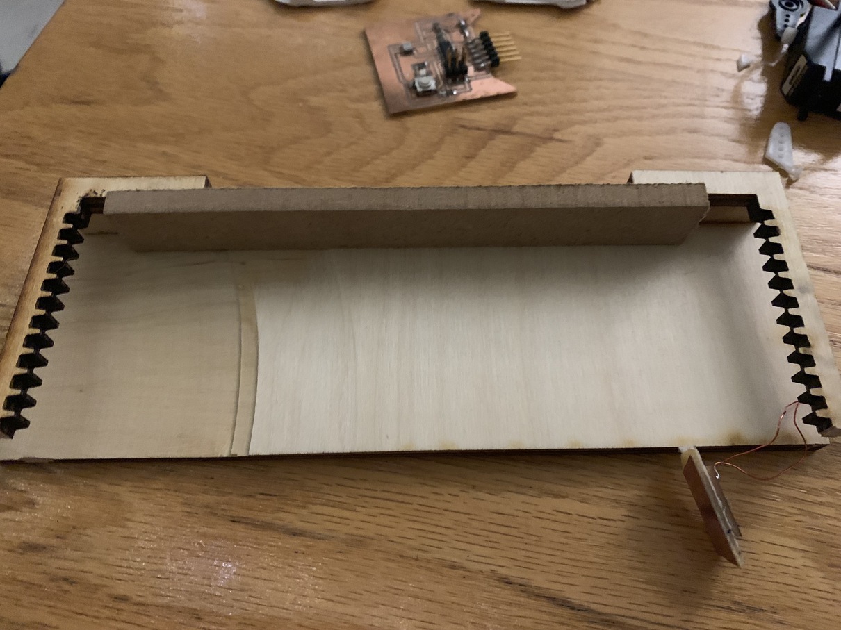
The next design choice came in how to move the doors themselves. Originally, I had planned to attach the rods to the doors with glue, as seen in the wooden pieces on the top and bottom. However, it ended up being smoother to use the 3D printed rod. To attach the door, I bandsawed a small piece of wood to the inner edge, so that the rod would have a surface to push/pull from.
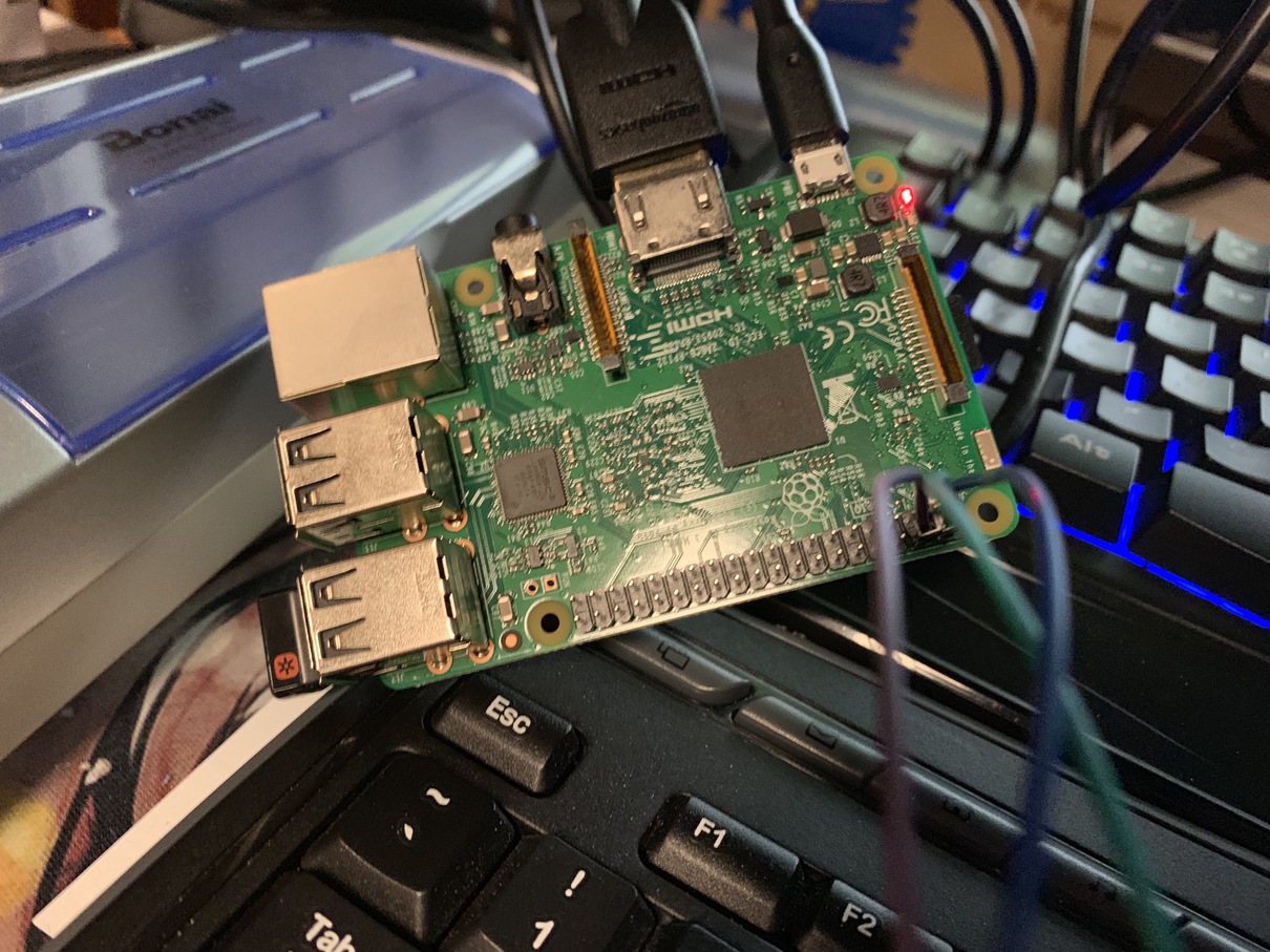
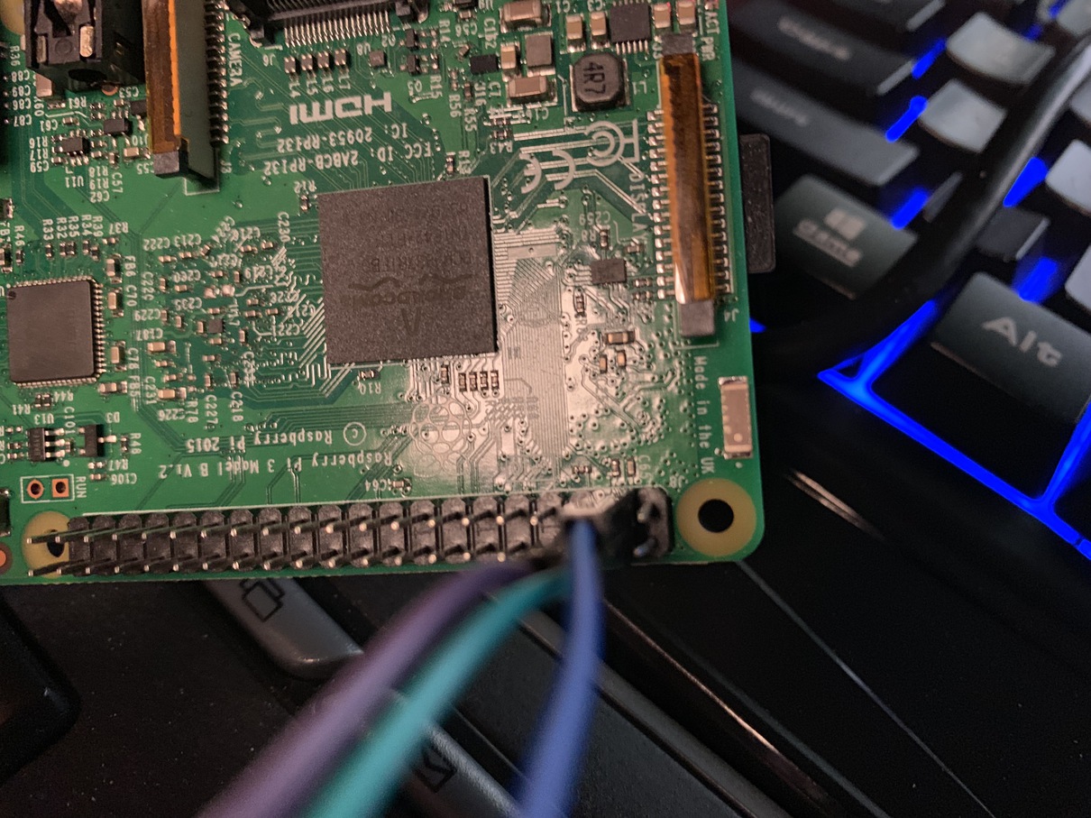
To control the servos electonically, I used the output port and PWM library of the central Raspberry Pi that would control the entire shrine. This raspi would take in input from the donation box sensor, and when a coin is detected, automatically open the doors. At this point, I just used the voltage and ground pins from the raspi itself, although at some point it may be neccessary to use a dedicated power source. The signal comes out from an I/O port on the raspi which we can control from code.
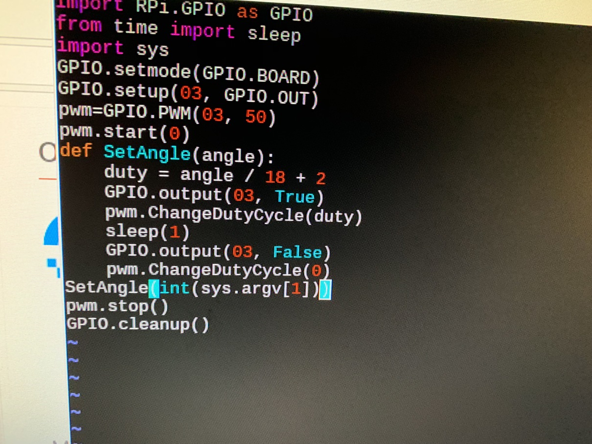
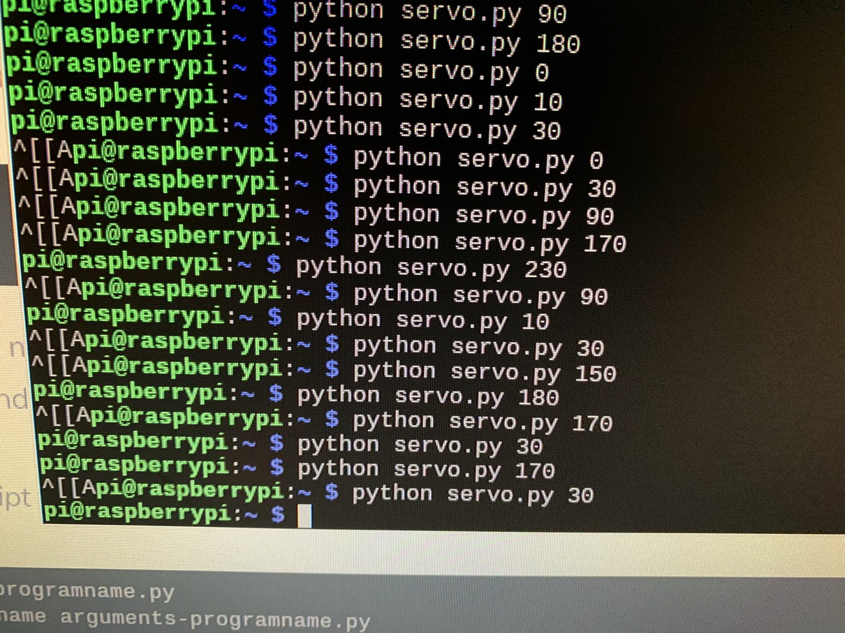
Controlling the servos though code uses the GPIO library of the raspi. Basically, a PWM library repeatedly writes pulses of high and low voltage to the signal pin, which the servo interprets as a desired angle to turn to. By sending different frequencies, we can control at what position the servo should rotate to.
Here is our baseline door moving with linear motion! The current issue is that since the servos only spin 180 degrees, the actual range of motion is very limited and the door cannot move very far. The next steps in the final project will be to try using a continuous rotation servo to solve this.