For this week we first had to program our board from week 5 and read a microcontroller datasheet. However, I first wanted to really understand what a microcontroller is in the first place.
A microcontroller (sometimes called an MCU) at its core is just a computer. Basically, the computer that you are using right now to read my website can run thousands of programs. Microcontrollers
on the other hand do one thing well. Microcontrollers have several characteristics:
- They are dedicated to one task a run a specific program. This program is stored in ROM and generally does not change.
- They are low power devices
- They have a dedicated input and output device.
All microcontrollers have these components:
This is sometimes called a processor or microprocessor, executes programs and is basically the brains of the system. This CPU is loading the program from somewhere.
This is where the microcontroller can store variables.
This is so the microcontroller can talk to people. And in many cases, microcontrolles have the Electrical Erasable Programmable Read-Only Memory (EEPROM)
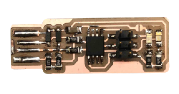
This week we have to program our board that we created in week 4 to do something. My board's input is a button and output is an LED. Because I have no experience, my goal for this week is to program my board so if I press the button the LED with turn on and if I don't press it, my LED will stay off. First, I decided to remake my board from week 2 because I messed up the solderning and decided it would be benificial for me to get the practice of making more boards.
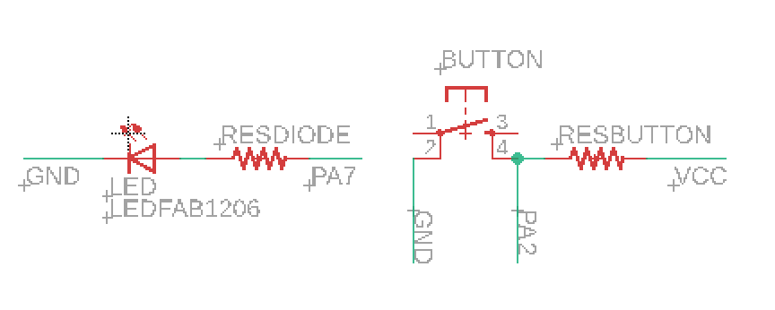
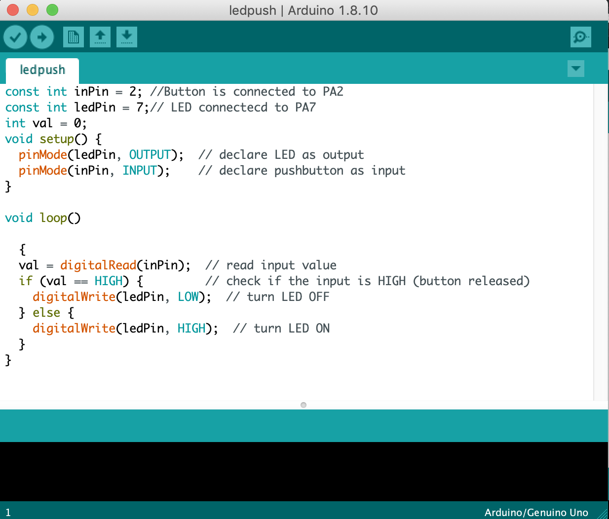
The first thing that I wanted to do when writing my code was determine what pins to assign my LED and button on my board. I looked at my eagle schematic and saw that my LED was connected to pin PA7 and my button is connect to pin PA2 on my Attiny45.
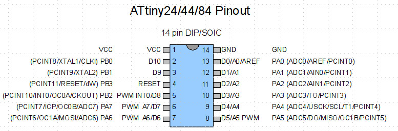
Then, I looked up an Attiny45 to Arduino pinout diagram to find the corresponding arduino pins for my button and LED to put in my arduino code. Luckily, it was easy this time and PA7 and PA2 corresponded to 7 and 2 accordingly.
My next step was starting on my code. I decided to use the arduino language, a set of C/C++ functions, to make my LED light up by the touch of a button. In the set up, I declared my LED as an output pin and my button as an input pin. The loop required a simple if statement that said if the input value from the button is high (button is not pressed), then the LED will have no current flowing through it and will be off. Otherwise, the LED will be on.
Unfortunatly, I have a mac and I havn't been able to figure out how to program by board by using my laptop yet. So I went on the Linux computer in the EECS lab and connected my board and my programmer to the computer using a ftdi and usb cable accordingly. The Attiny45 libraries were already downloaded and imported into the Arduino in the computer so all I had to do after that was hit upload and the button turned on the LED when I pressed it!
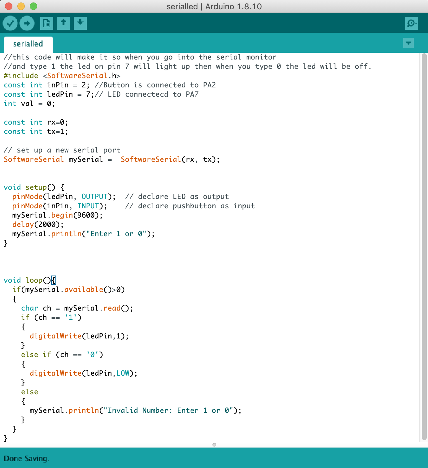
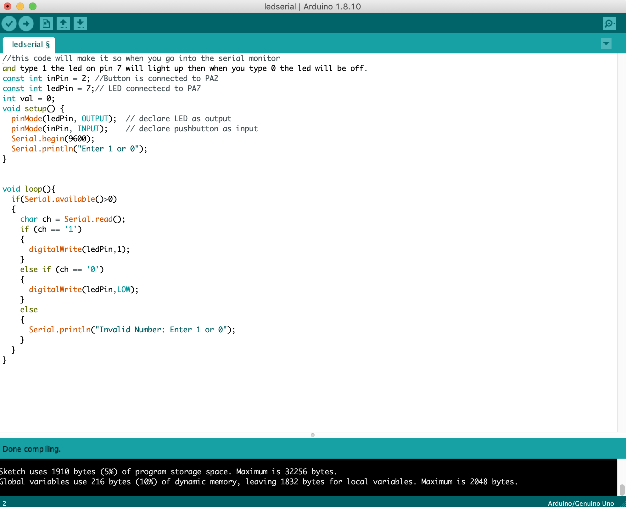
I also wanted to program my board to interact with the serial monitor. I wanted to program my board so that when you go into the serial monitor and type 1 the led on pin 7 will light up then when you type 0 the led will be off. I first tried coding it by just using Serial from arduino, however I quickly realized that this wouldn't work with the board that I created.
In order to program my board to do what I wanted I have to use Software Serial. The Arduino hardware has built-in support for serial communication on pins 0 and 1 (which also goes to the computer via the USB connection). The SoftwareSerial library has been developed to allow serial communication on other digital pins of the Arduino, using software to replicate the functionality (hence the name "SoftwareSerial"). It is possible to have multiple software serial ports with speeds up to 115200 bps. A parameter enables inverted signaling for devices which require that protocol. There are a few limitations to software serial that would be relevent to future projects. For example, if using multiple software serial ports, only one can receive data at a time. In this case it is ok because I only want one output (LED), but that would be an important thing to keep in mind.