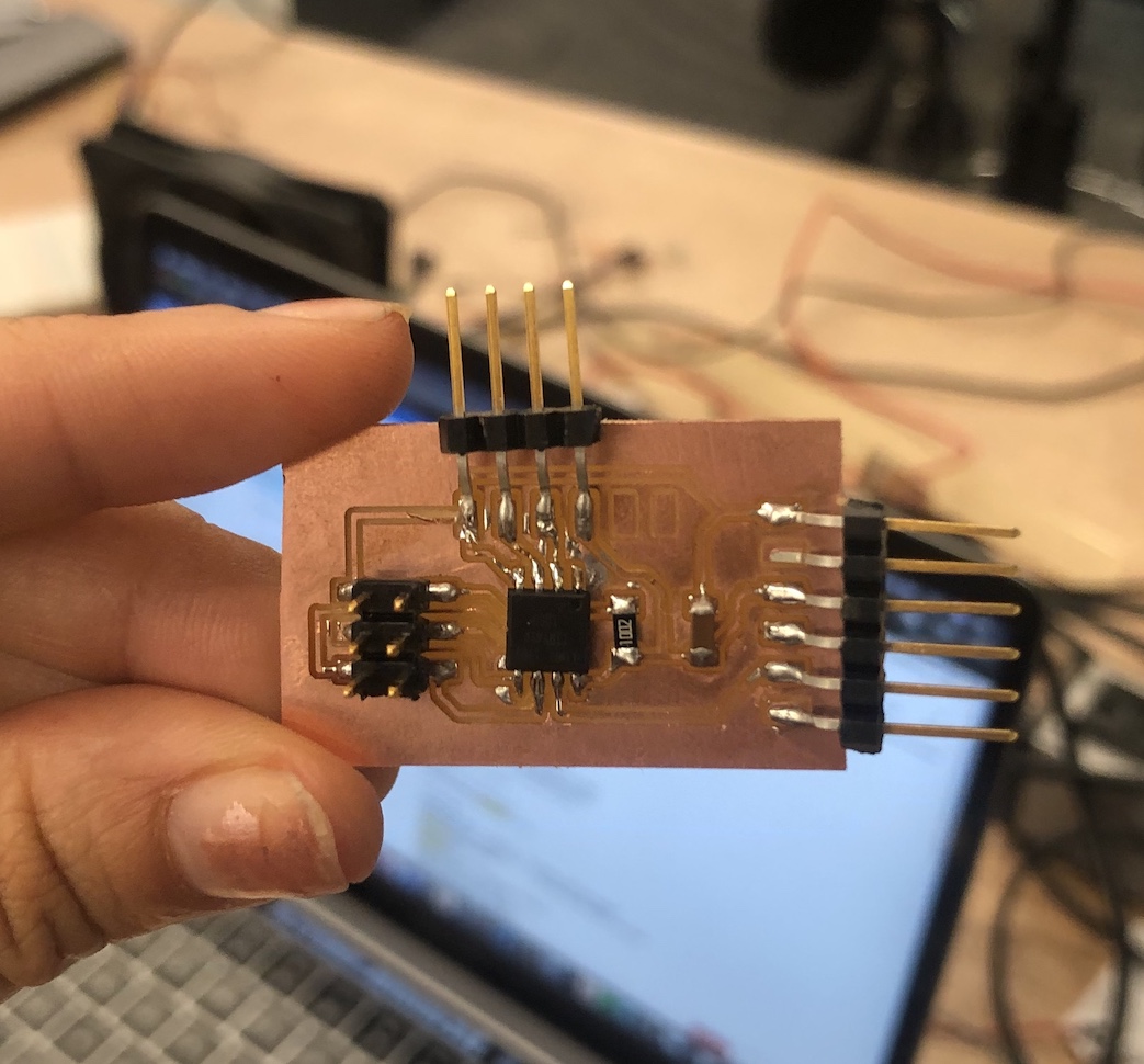
For this week, I created an ultrasonic sensor board from scratch and recreated Neil's board for the accelerometer because I wanted to figure out how that board worked aswell.
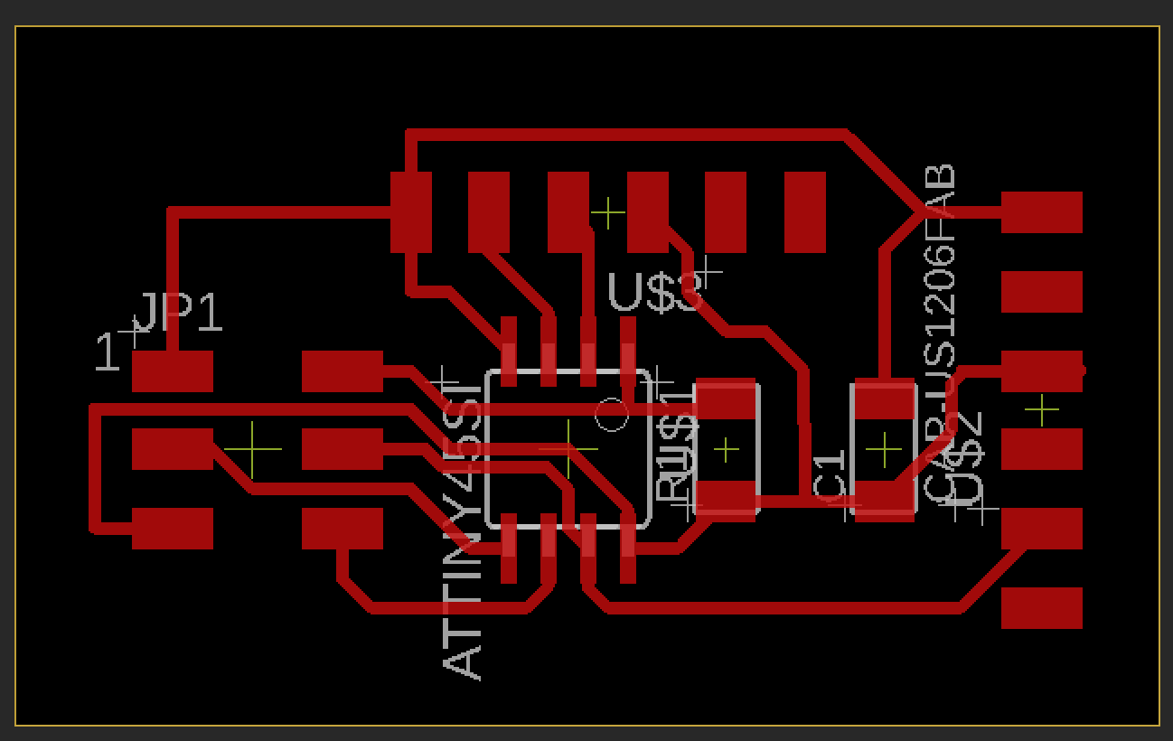
This was the first time that I used the Other mill. This mill doesn't need to use the CBA modules and can just take an Eagle file and mill the board, which I found way more convienient.
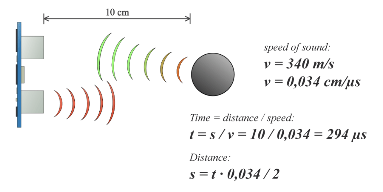
Before programming my board, I wanted to really understand how an ultrasonic sensor works.Ultrasonic sensing is one of the best ways to sense proximity and detect levels with high reliability. An ultrasonic sensor is an instrument that measures the distance to an object using ultrasonic sound waves. An ultrasonic sensor uses a transducer to send and receive ultrasonic pulses that relay back information about an object's proximity. High-frequency sound waves reflect from boundaries to produce distinct echo patterns.work by sending out a sound wave at a frequency above the range of human hearing. The transducer of the sensor acts as a microphone to receive and send the ultrasonic sound. Our ultrasonic sensors, like many others, use a single transducer to send a pulse and to receive the echo. The sensor determines the distance to a target by measuring time lapses between the sending and receiving of the ultrasonic pulse.
In terms of the HC-SR04 Ultrasonic Module, it has 4 pins, Ground, VCC, Trig and Echo. The Ground and the VCC pins of the module needs to be connected to the Ground and the 5 volts pins on the Arduino Board respectively and the trig and echo pins to any Digital I/O pin on the Arduino Board. In order to generate the ultrasound you need to set the Trig on a High State for 10 µs. That will send out an 8 cycle sonic burst which will travel at the speed sound and it will be received in the Echo pin. The Echo pin will output the time in microseconds the sound wave traveled.
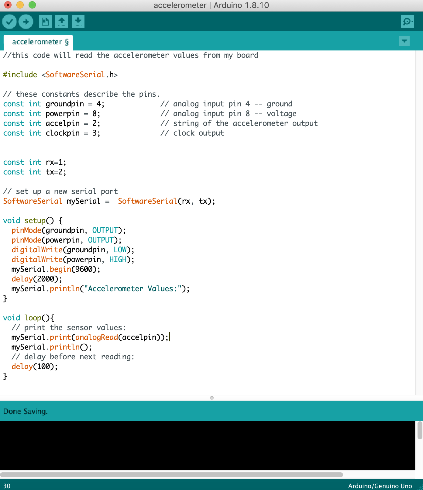
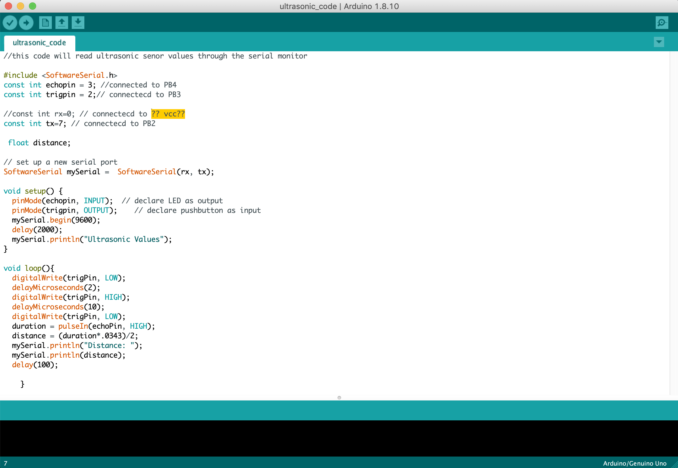
This was my final working code that I used that applied the math from the image above. While doing this, I was confused about how my software serial was going to work because my rx pin was not connected to anything. However, I discovered that software serial will still work as long one of the pins are connected and you can write a random pin for the other pin.
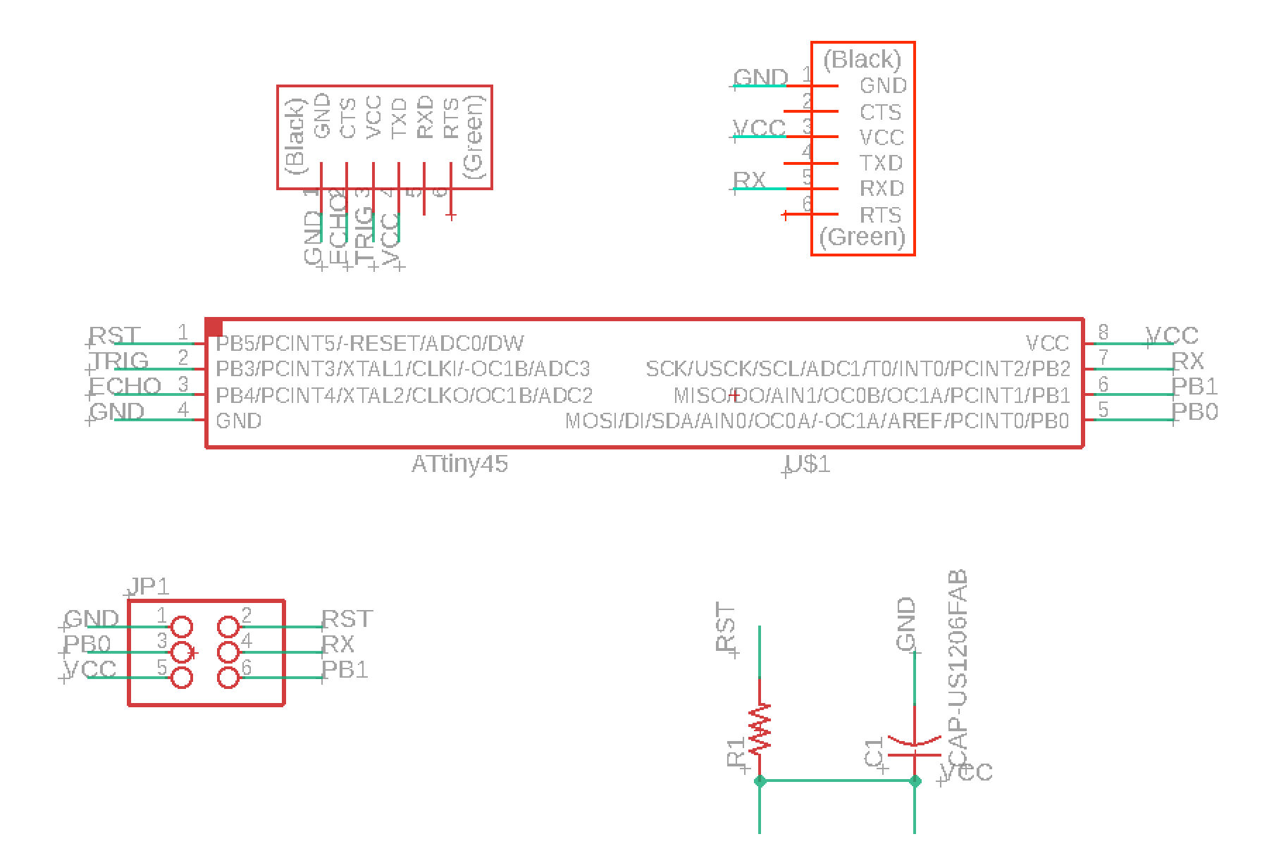
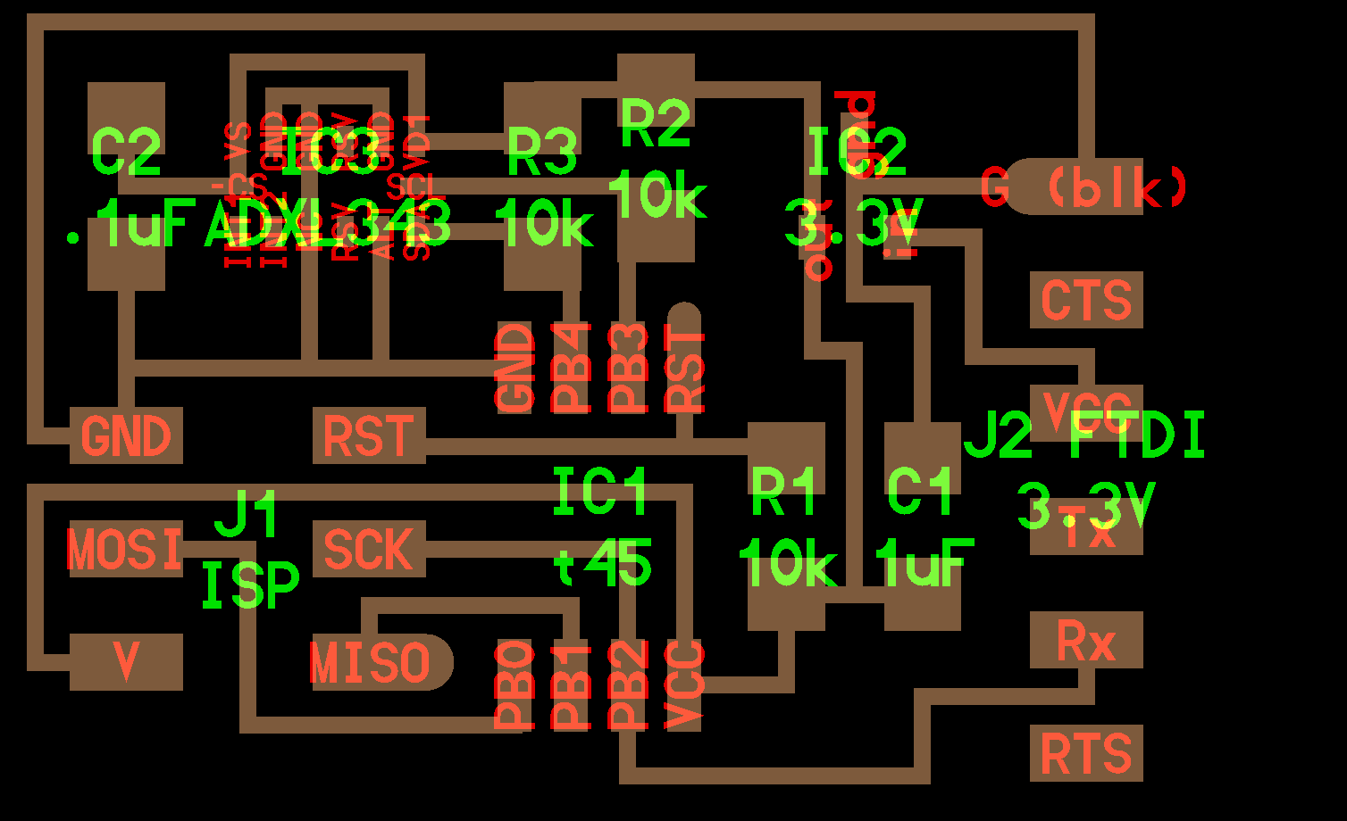
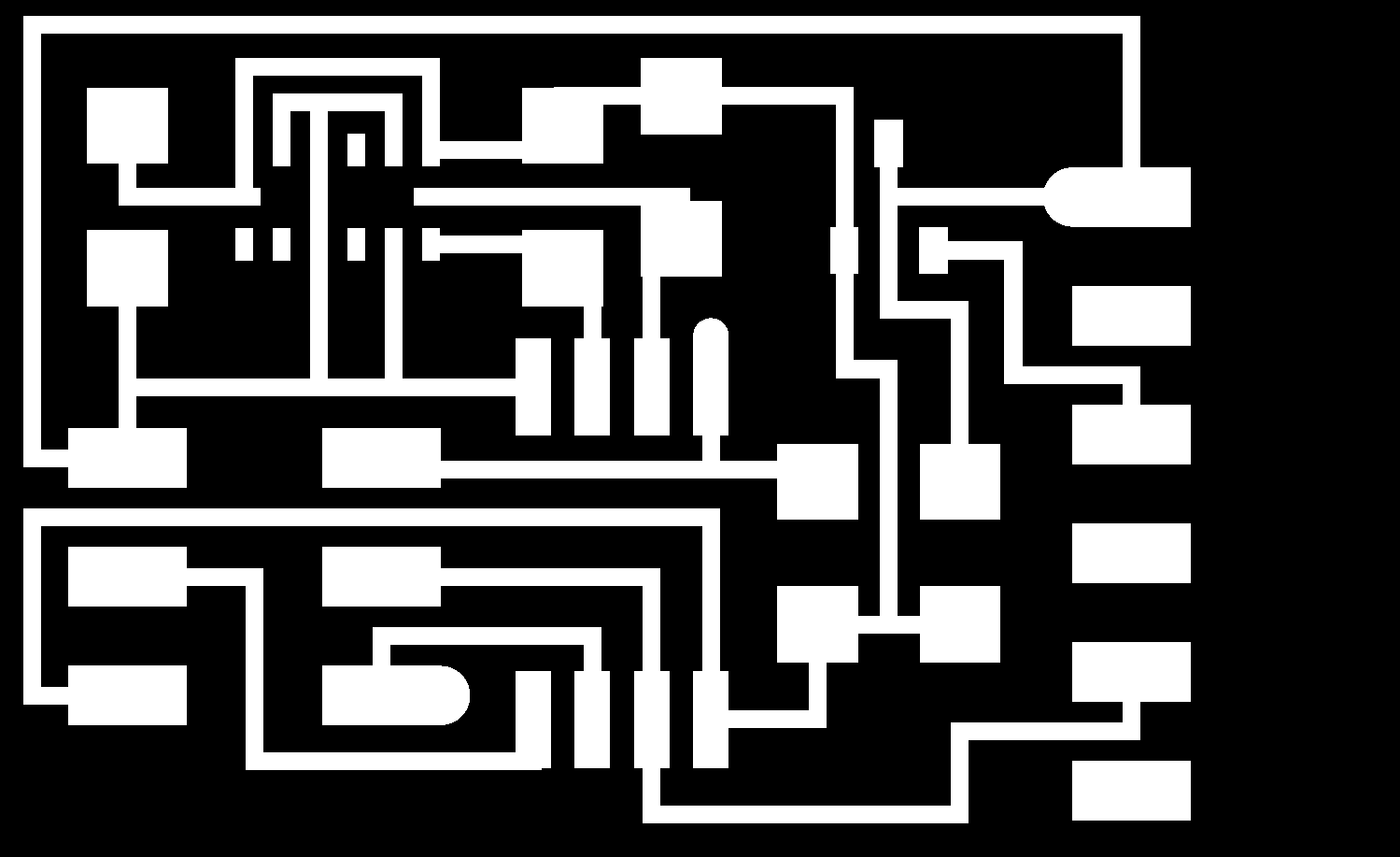
Before, for my final project I wanted to create a jacket that would emmit sirens and LED lights. However, I wanted to think of a good way to trigger turning on the alarm from the jacket that couldn't really be done accedentally, for example the push of a button. Therefore, I wanted to use an accelerometer to see if I could measure and tell when someone either falls (being pushed to the ground) or is waving their arms frantically (if the accelerometer is placed on the arm of the jacket. From the CBA website, I used the board files and started creating the board from that.
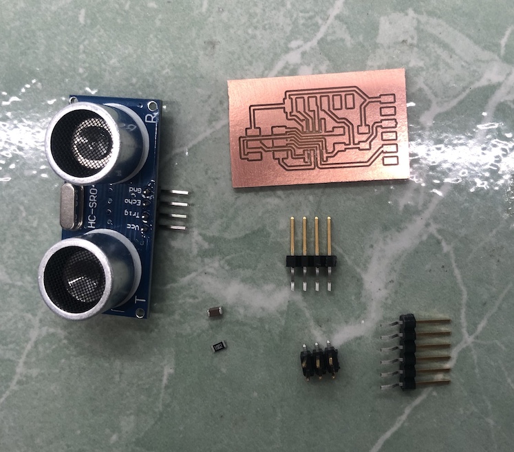
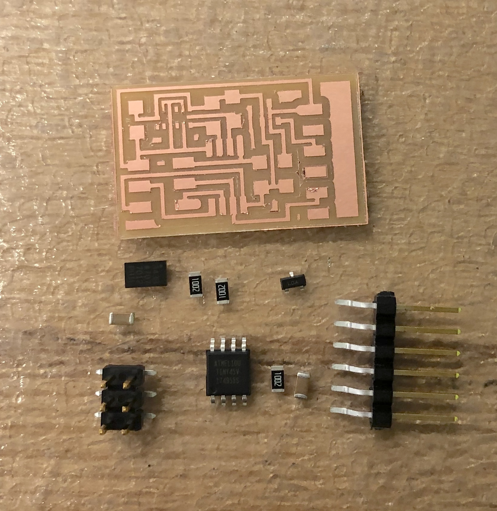
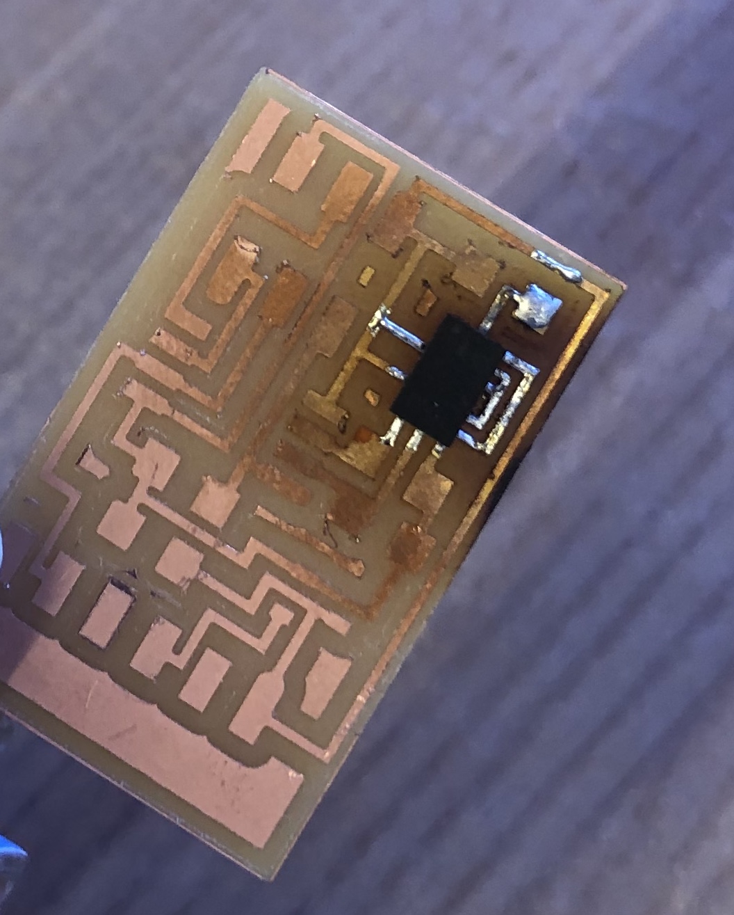
After creating the board, I went ahead and grabbed all the pieces I had to solder on to the board and decided to start with the accelerometer because it looked like it would be the hardest to solder on, so incase it didn't work I could start over again and not lose as much work (I ended up needing to start over again).
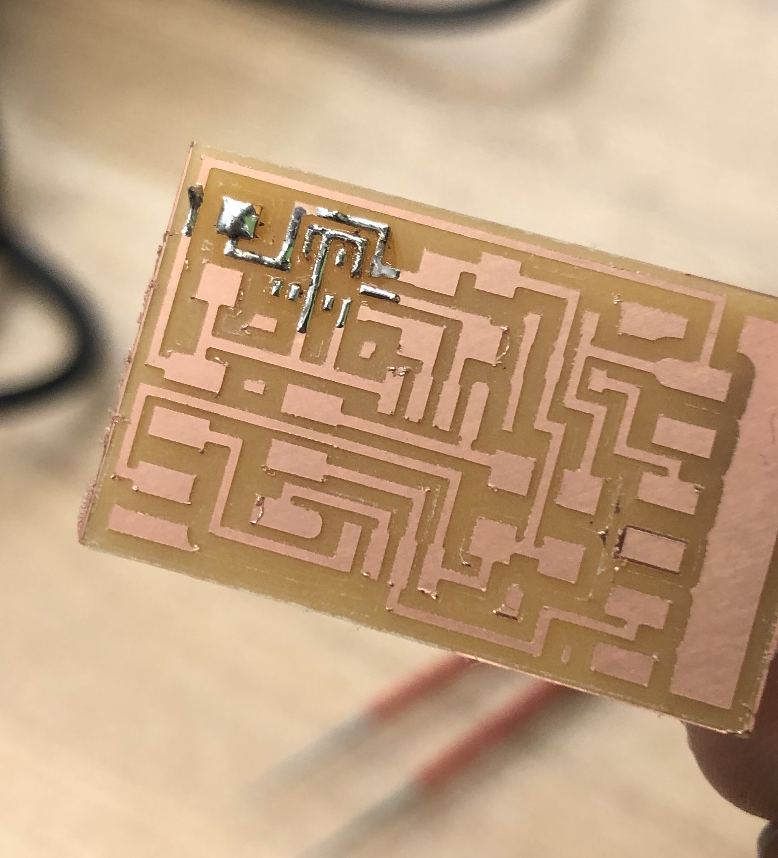
I first tried soldering it on using regular solder and then putting hot air over it to stick it to the board. However, as you can see, I wasn't able to get it on correctly and fully flat on the board. After a few more tries, I ended up burning my board and I decided to play it safe and make another board
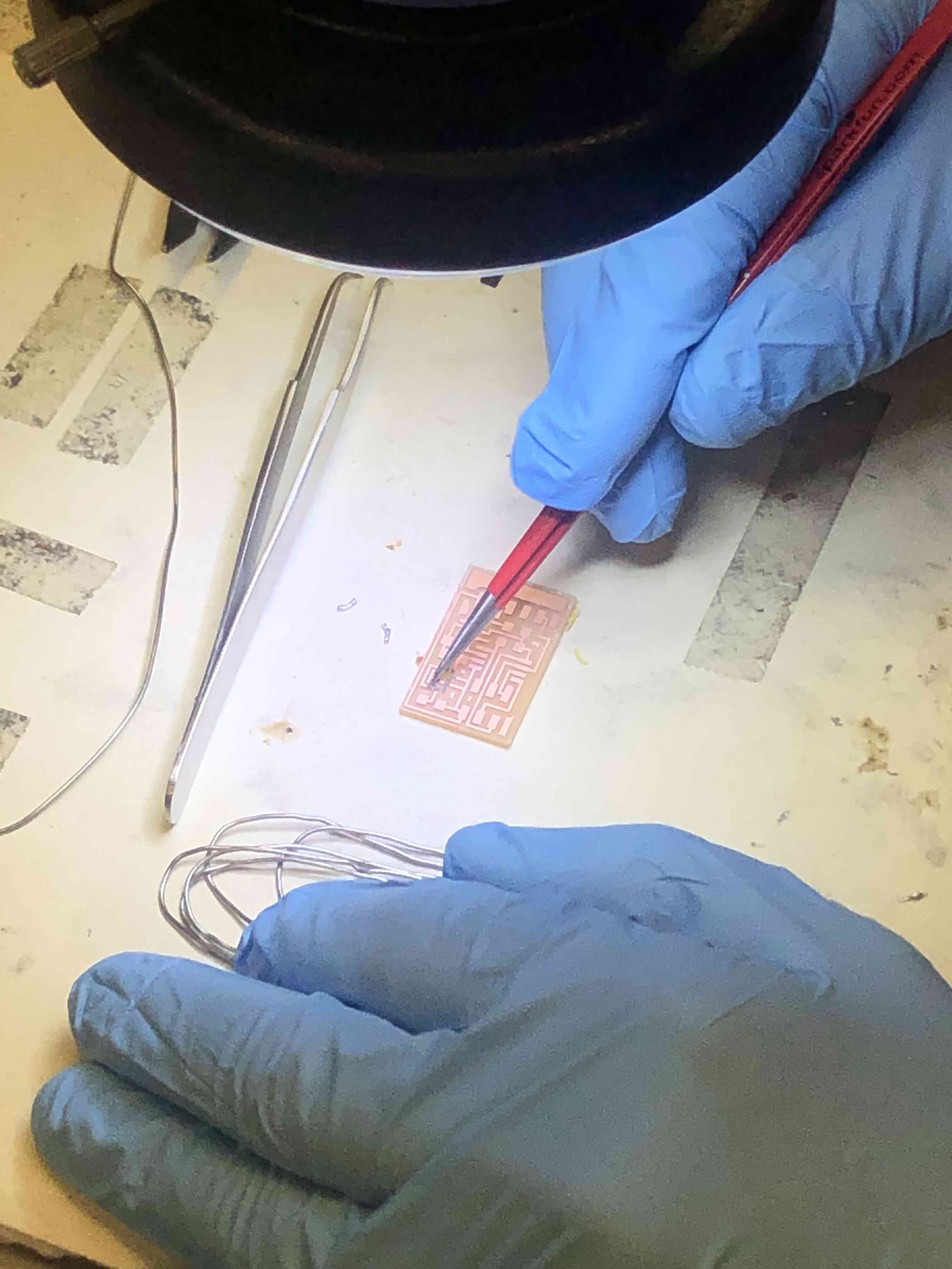
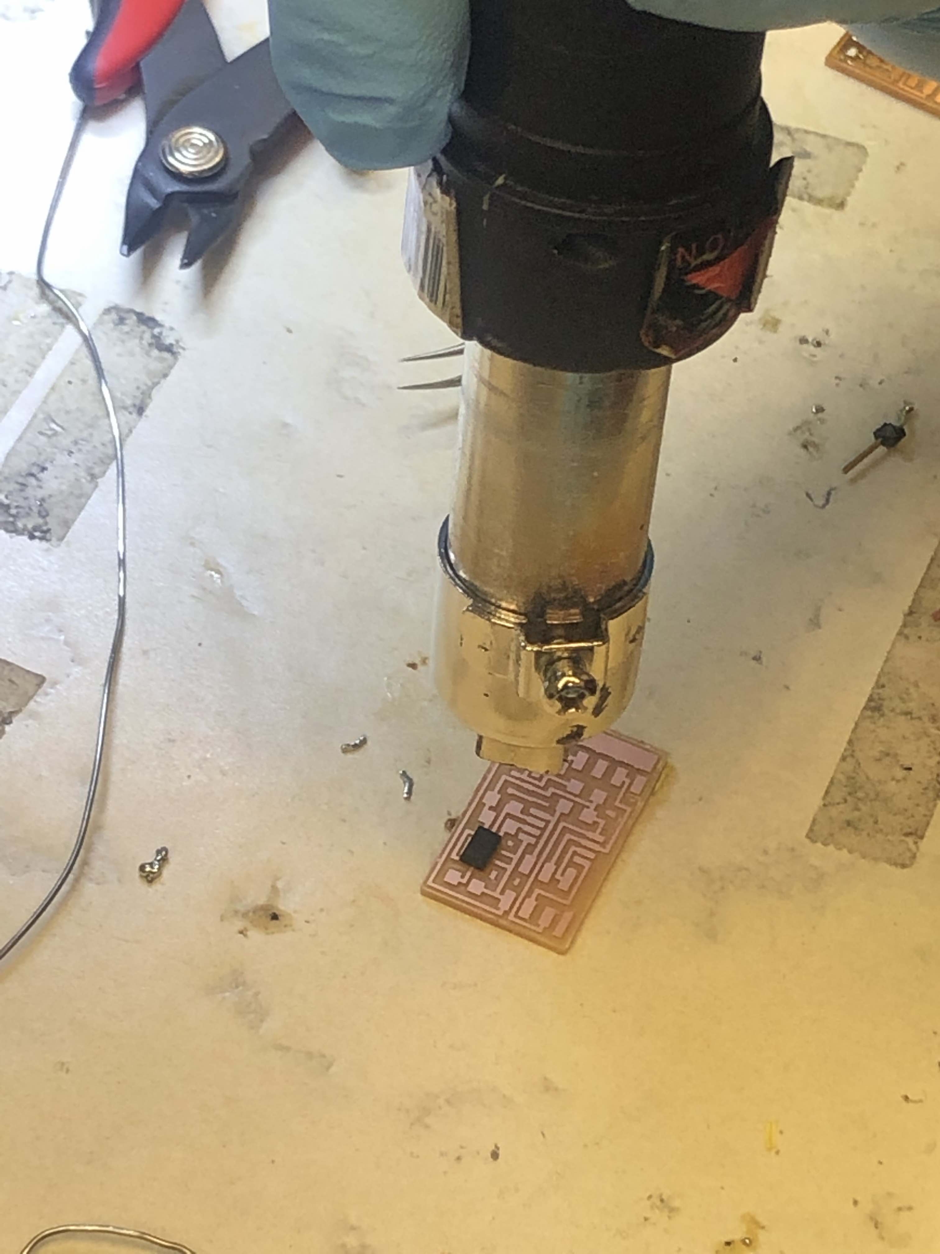
The second time around I used solder paste and hot air to make sure the part was correctly placed on the board and all the pads of the accelerometer were touching the board.
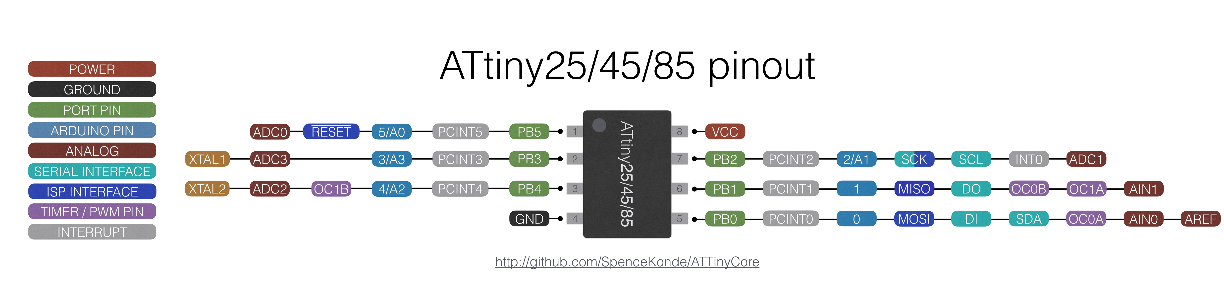
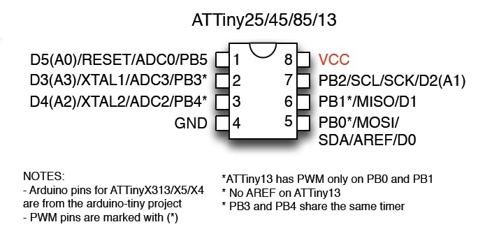
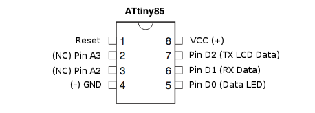
In order to first start writing my code, I needed to know where all the pins of my VCC, GND, and Signal are in terms of my microconroller, which is the Attiny45, and then which pins on Arduino they are. Because I was trying to display the data on the serial moniter I also needed to find the tx and rx pins on my Attyiny45.
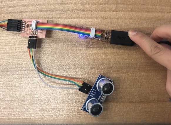
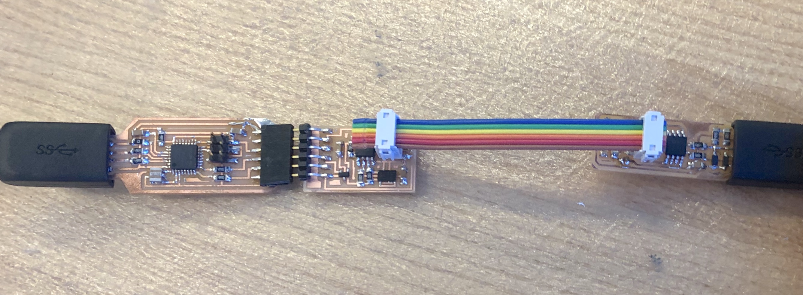
Here is a picture of my new accelerometer board connected to my programmer and a homemade ftdi cable.
The Arduino hardware has built-in support for serial communication on pins 0 and 1. The SoftwareSerial library has been developed to allow serial communication on other digital pins of the Arduino, using software to replicate the functionality.