I was interested in building a drone in the future and Anthony gave me a drone that was just sitting around in his office.
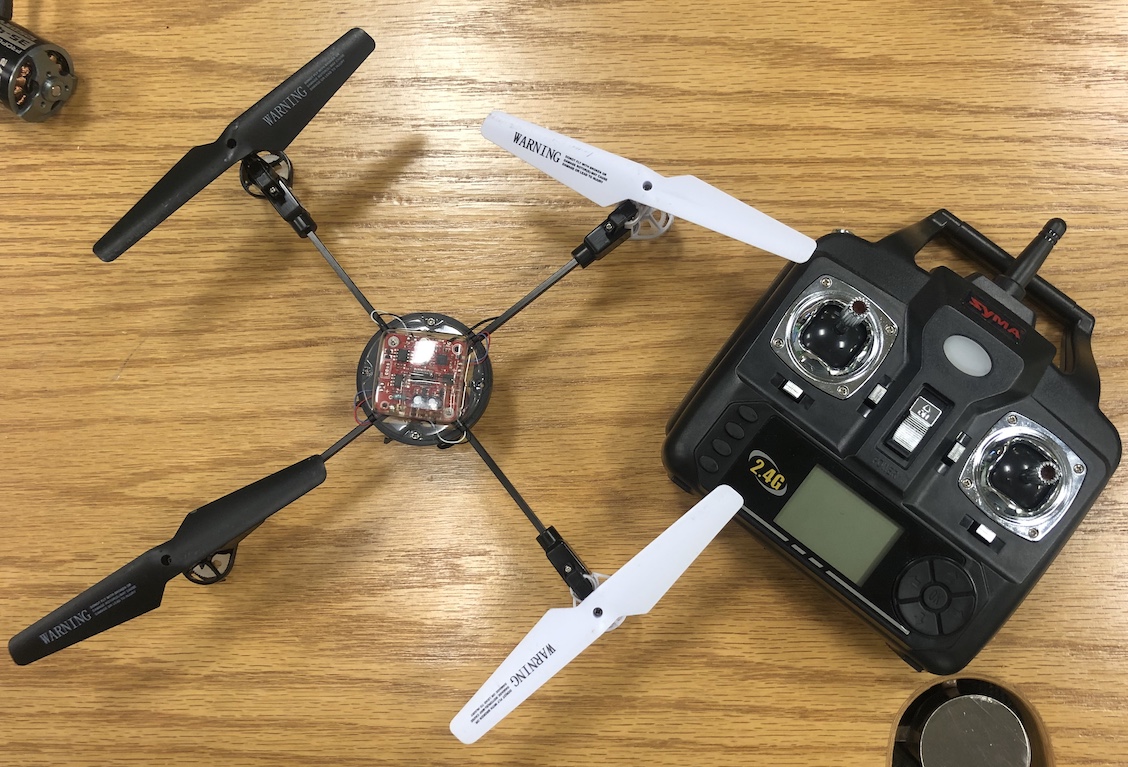
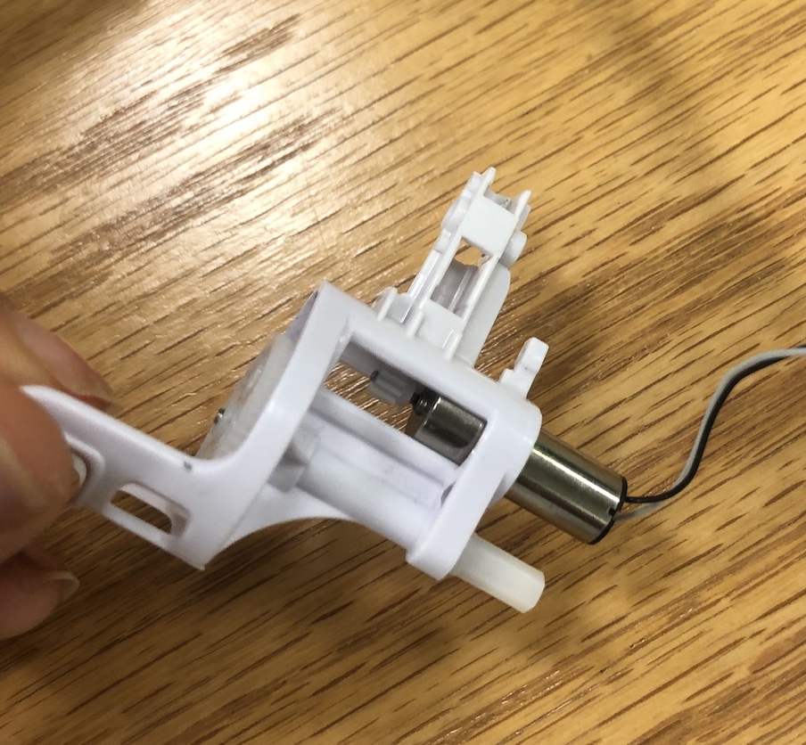
I took it apart and wanted to create a motor board to see if I could control the motors. It was a SYMA drone and was able to find the motors that was used to see what voltage and current it needs to know what regulator to add onto the board.
Operating Voltage: 3.7v at 500mAh
Dimensions: 7 x 20 mm (D x L)
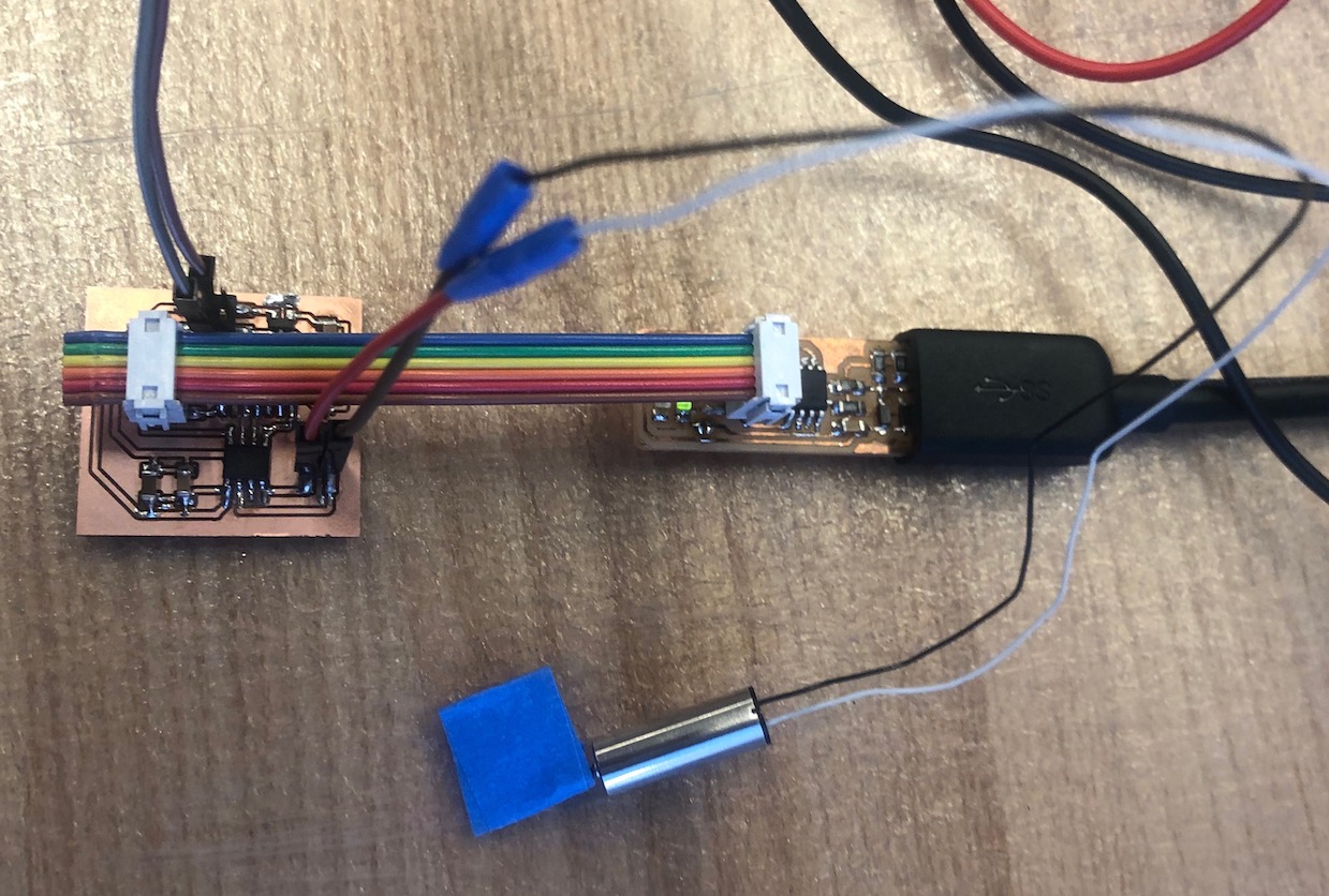
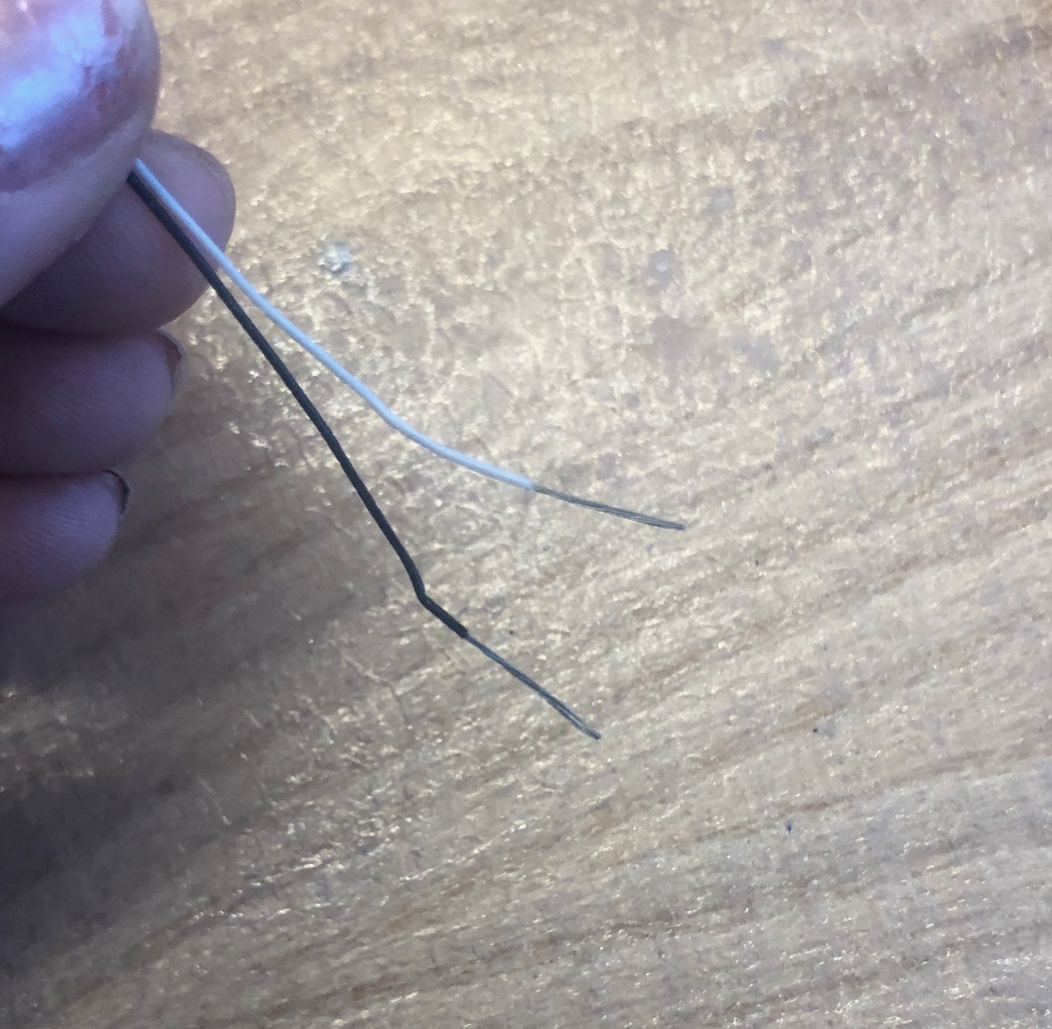
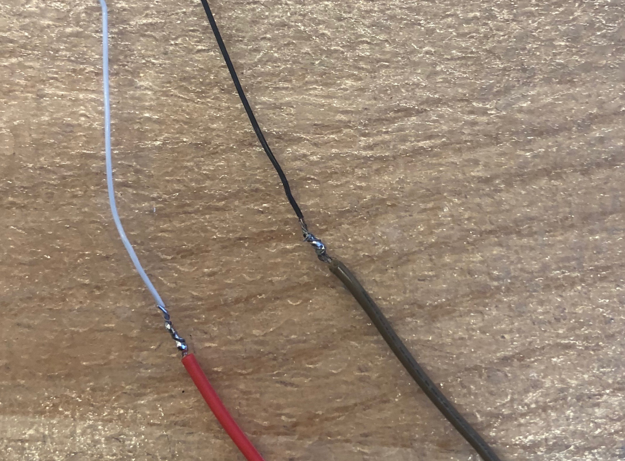
I soldered the pins of the motor to another wire that had a female header so I could plug it in the board that I made.
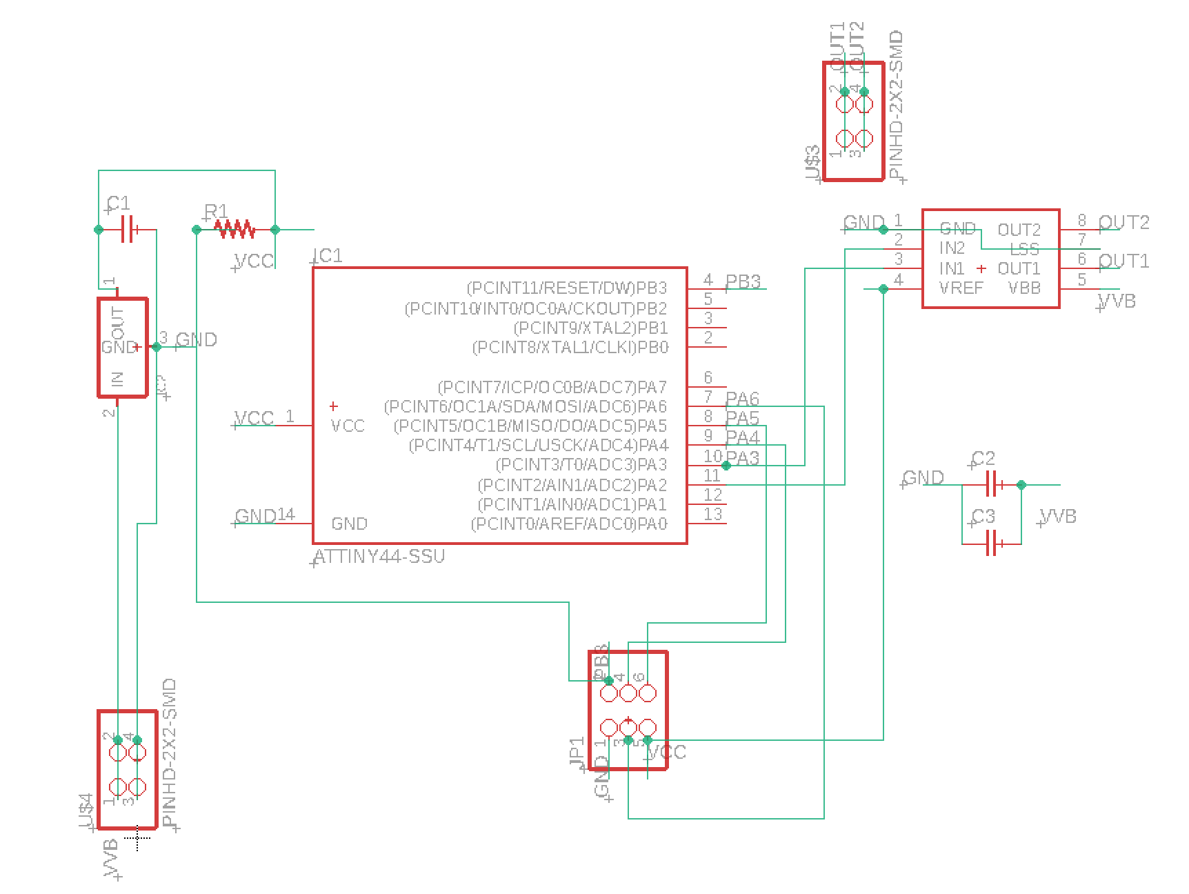
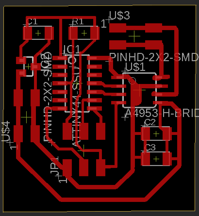
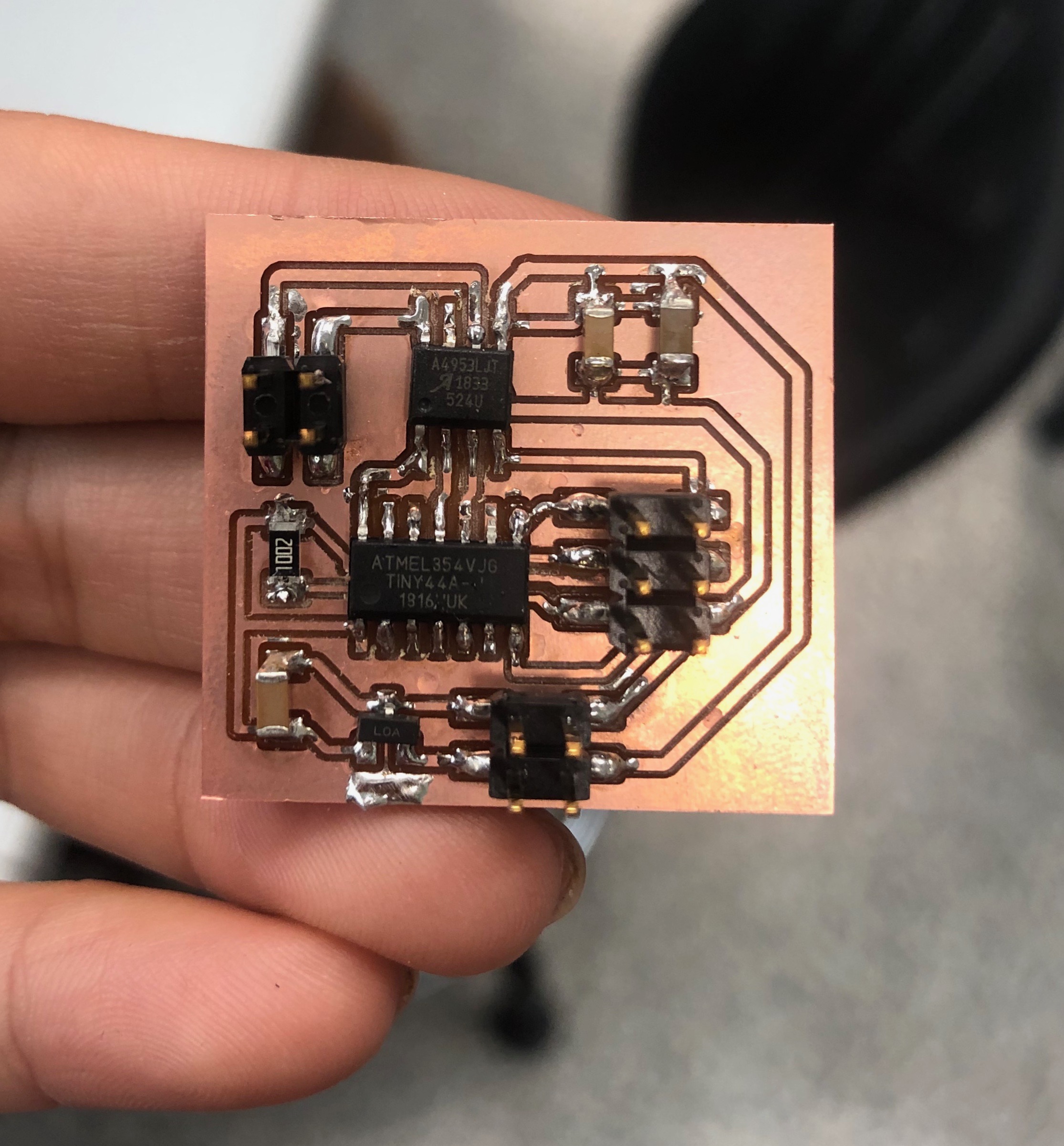
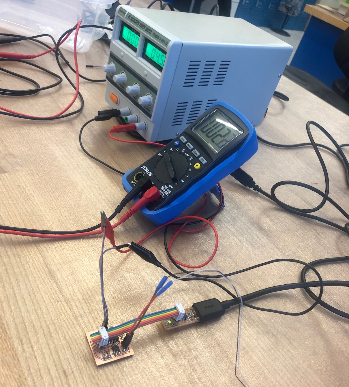
This board was the first board that I created that has an external power source, so that power isn't just coming from ftdi port. Before programming my board, I wanted to make sure that my motor was working to help move along the debugging process. I connectecd both sides to a DC power supply and the motor turned!
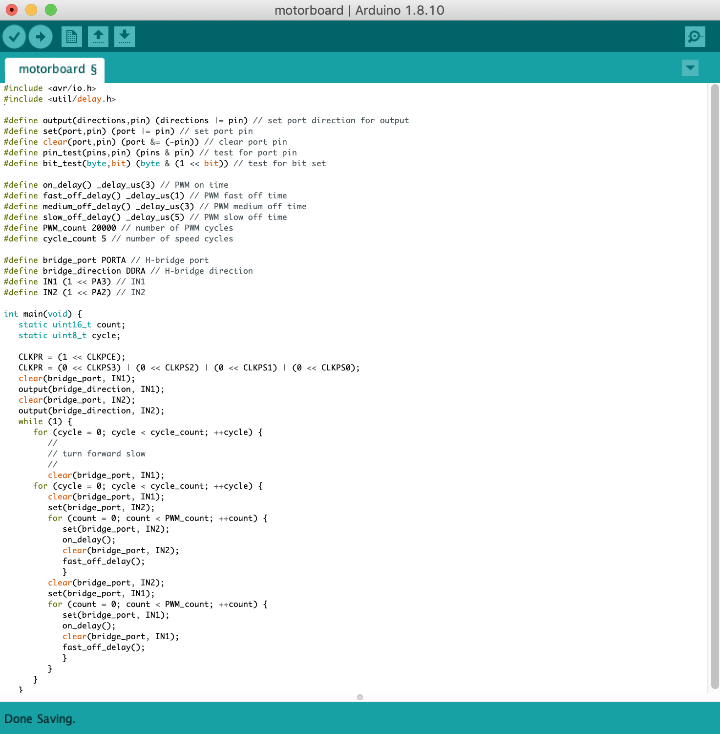
Pulse Width Modulation, or PWM, is a technique for getting analog results with digital means. Digital control is used to create a square wave, a signal switched between on and off. This on-off pattern can simulate voltages in between full on (5 Volts) and off (0 Volts) by changing the portion of the time the signal spends on versus the time that the signal spends off. The duration of "on time" is called the pulse width. To get varying analog values, you change, or modulate, that pulse width. Pulse-width modulation (PWM) of a signal or power source involves the modulation of its duty cycle, to either convey information over a communications channel or control the amount of power sent to a load.The simplest way to generate a PWM signal is the intersective method, which requires only a sawtooth or a triangle waveform (easily generated using a simple oscillator) and a comparator. When the value of the reference signal (the green sine wave in figure 2) is more than the modulation waveform (blue), the PWM signal (magenta) is in the high state, otherwise it is in the low state.
PWM can be used to reduce the total amount of power delivered to a load without losses normally incurred when a power source is limited by resistive means. This is because the average power delivered is proportional to the modulation duty cycle. After understanding what PWM does, I was able to understand Neils code and use it on my board to get the motor running.