Week 3: Electronics Production
Characterizing the Mill
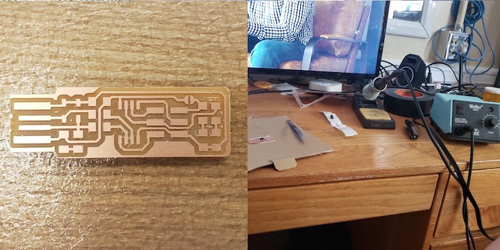
To characterize the mill, my group used the 1/64" bit to mill out the line-test image. We wanted to see how small we could get our traces before they became nonexistent.
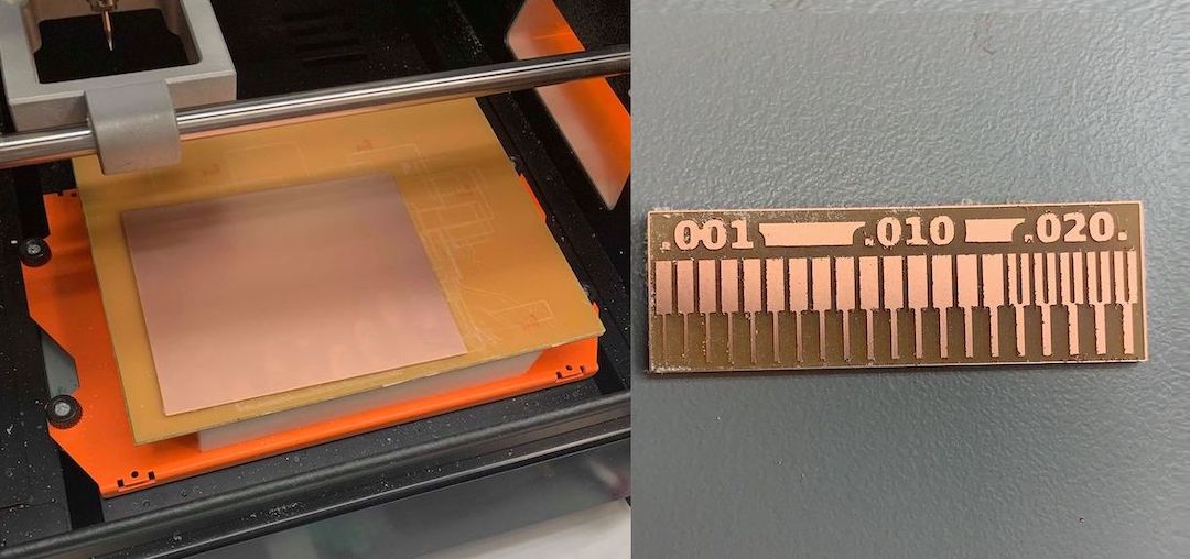
Looking at the board, most traces are visible. It appears as though the mill would be able to etch traces down to around 0.003". On the other side, it was not able to carve out any paths thinner than around 0.016". We did not try using the 1/32" bit which I assume will have more trouble with the finer traces. I will update if I characterize the mill using any other sizes.
Milling the board
My first step in designing my programmer was milling out the board. I used mods to mill the traces and the outline. The workflow for milling the traces is shown below: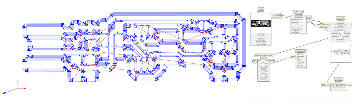
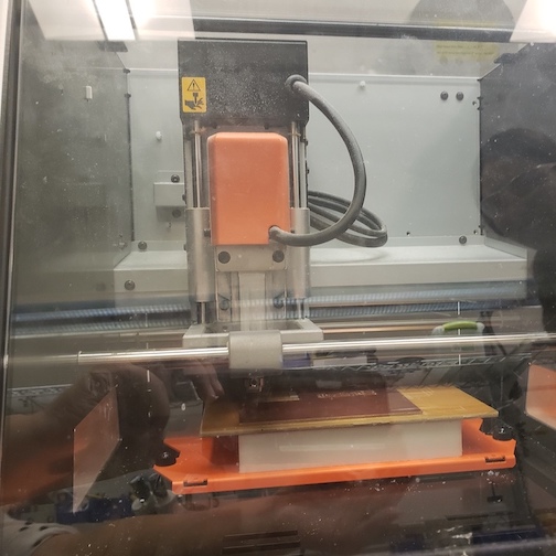
On my next attempt, I realized that I didn't pull the bit down enough so the bit only brushed the very top. The threads were not deep enough so I had to redo positioning the origin, making sure to push down slightly before tightening the set screw. Since I kept the x and y the same, I was able to just restart the process again on the same piece of board.
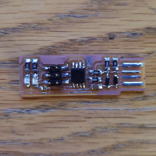
Soldering components
I followed Brian's tutorial on building the FabTinyISP to populate my board.
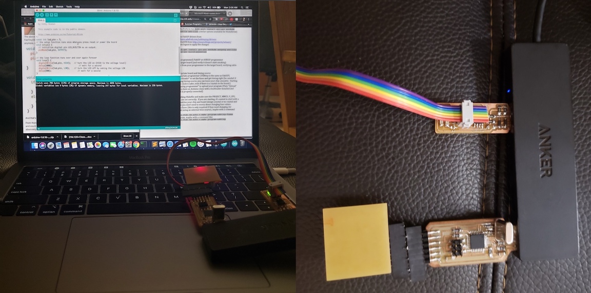
Programming and testing
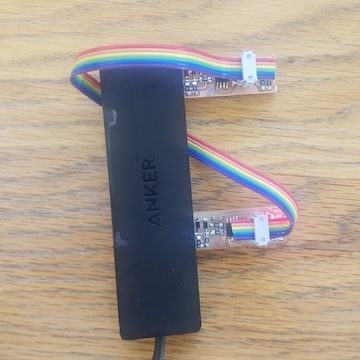
Since my computer only has USB-C ports, I was worried that I would have issues. I plugged my board into a USB-3.0 hub which connected to a USB-C dongle which I plugged into my computer. Thankfully, this seemed to work just fine on both my MacBook and my PC running Ubuntu. When I plugged my board in, I realized I had swapped the red and green LEDs by accident so my green LED lit up to indicate that the board was powered.
My friend who took HTAA last year let me borrow her programmer to program my board. I struggled for a bit because I assumed that only one board needed to be powered and the other board could recieve power through the V_prog pin, but I realized that both boards needed to be plugged into my USB hub. After that, it was easy to follow Brian's instructions to flash the firmware and blow the reset fuse.
After I removed the jumper, I wanted to verify that my programmer was working. My friend let me borrow some of the other boards that she made for the class so I could try using my programmer. I got a sneak peek of week 5 and programmed the echo hello-world board to make an LED turn on in response to a button press. It was very rewarding to see my programmer in action and I'm even more excited now for week 5.