Week 5: Electronics Design
Designing the board
The first part of this week's assignment was to redraw the echo hello-world board and add a button and LED. I used Eagle to design my board, making sure to import in the fab lab library and to edit the DRC to match the design rules that the EECS group settled on in our electronics production week. I added a LED, 499 ohm resister, and a button. The LED is wired up to pin 6 of the attiny and the button is wired to pin 10. The schematic is
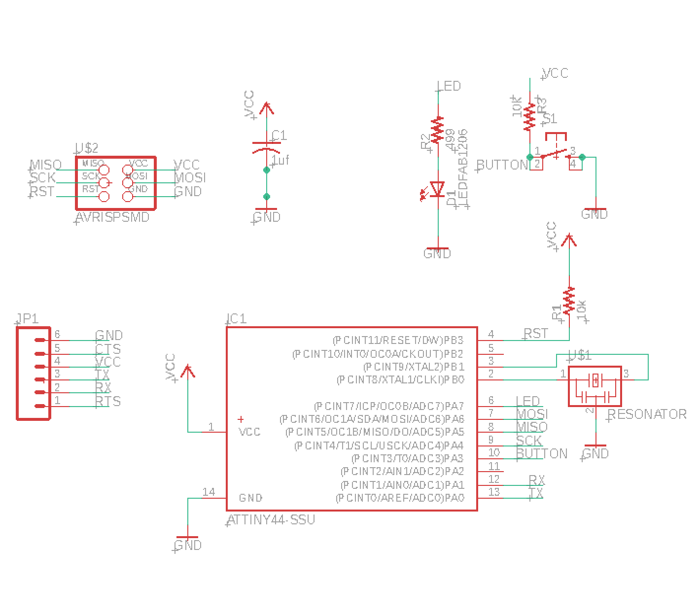
which shows the connections I made in order to add in the button and LED. The board produced in Eagle is:
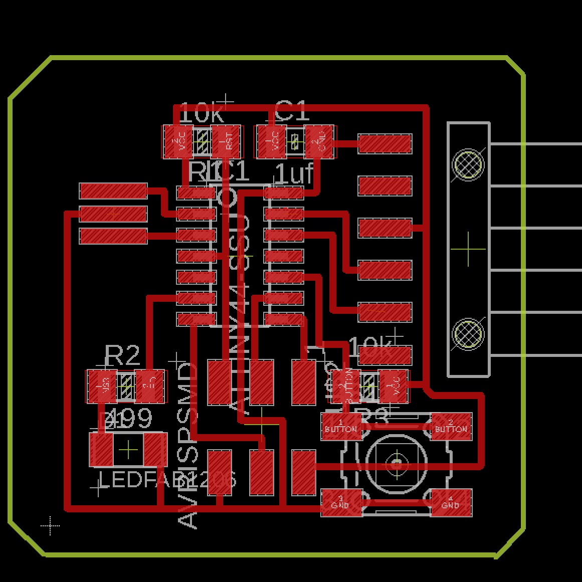
I exported the Eagle file to a png, making sure to turn off the layers containing text to generate a monochrome image that could be sent to mods.
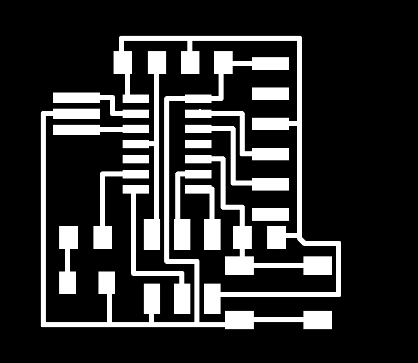
The image file of the outline that Eagle originally generated had a white line around the edge of the board. I used GIMP to fill in the white line so that mods could calculate the path correctly.
Milling the board
Attempt #1
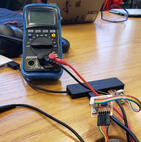
After I finished milling my first board, I that the traces on the border of my design were very close to the edge. After I soldered the components on and probed the board using a multimeter, I realized that by using a female 6-pin header and not being careful about where I placed it, I accidentally made contact with the VCC line with all the pins of my header. When I removed the 6-pin header, the traces came off of my board as well so I decided to remill, making the board slightly bigger so it would be easier to work with.
Attempt #2
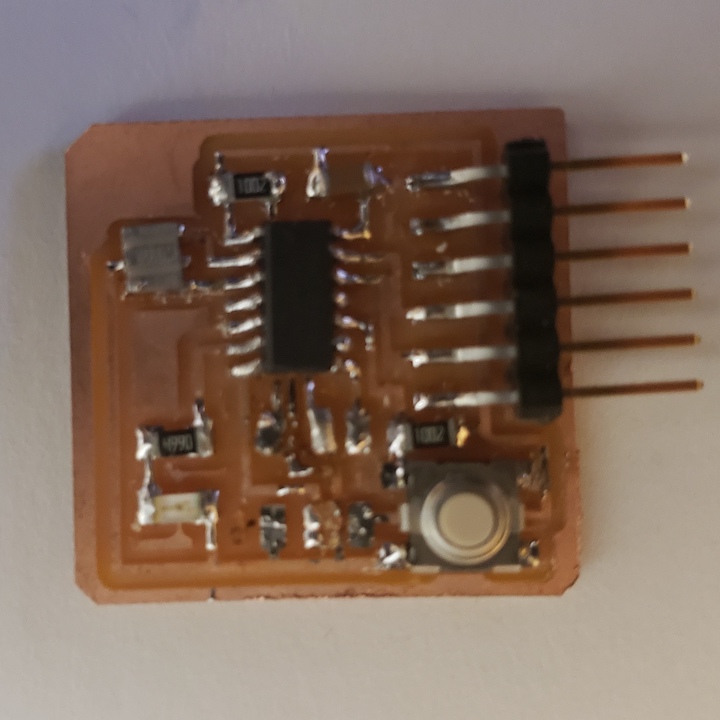
On my next attempt, I made sure to use the male 6-pin header. I soldered all the components but had issues when I tried programming my board. On closer look, I realized the clearance on a few of my traces were too small to be milled out by the Roland SRM-20 which was causing my board to short. Although I initially tried going in with an X-Acto knife to clean out the merged traces, I decided to just start from scratch since I had another board milled out already.
Attempt #3
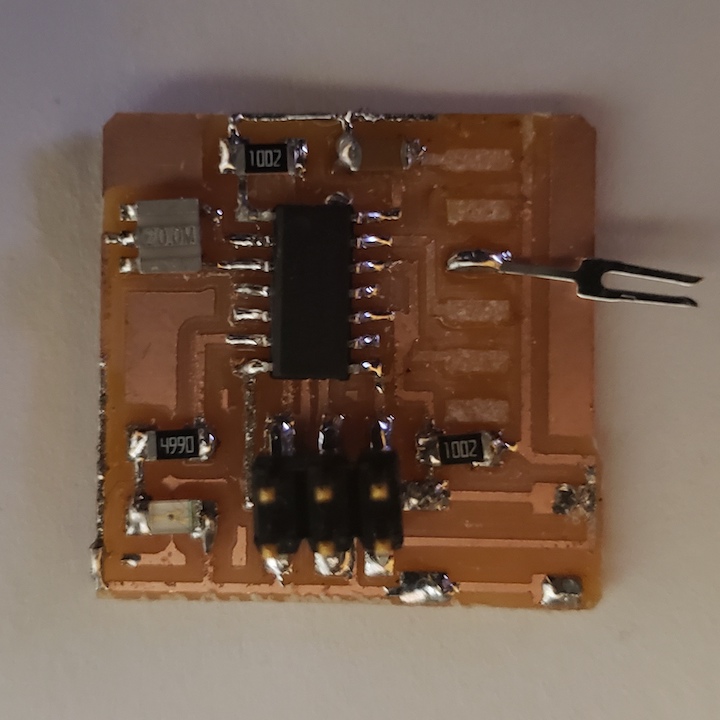
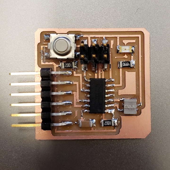
For this board, I started off by going in with an X-Acto knife and cleaning up the merged traces. After verifying with an multimeter that the connections were good, I soldered my components. While trying to program, I noticed that I got a "Too Much Power Drawn" error when trying to test out the button. By probing, I realized that I had a short from the button to VCC, so I would be connecting VCC and GND whenever the button was activated. Once I fixed that short, I was able to program the board.
Testing the board
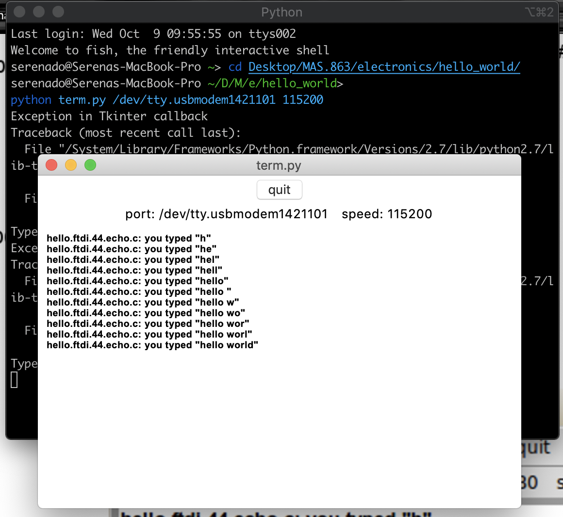
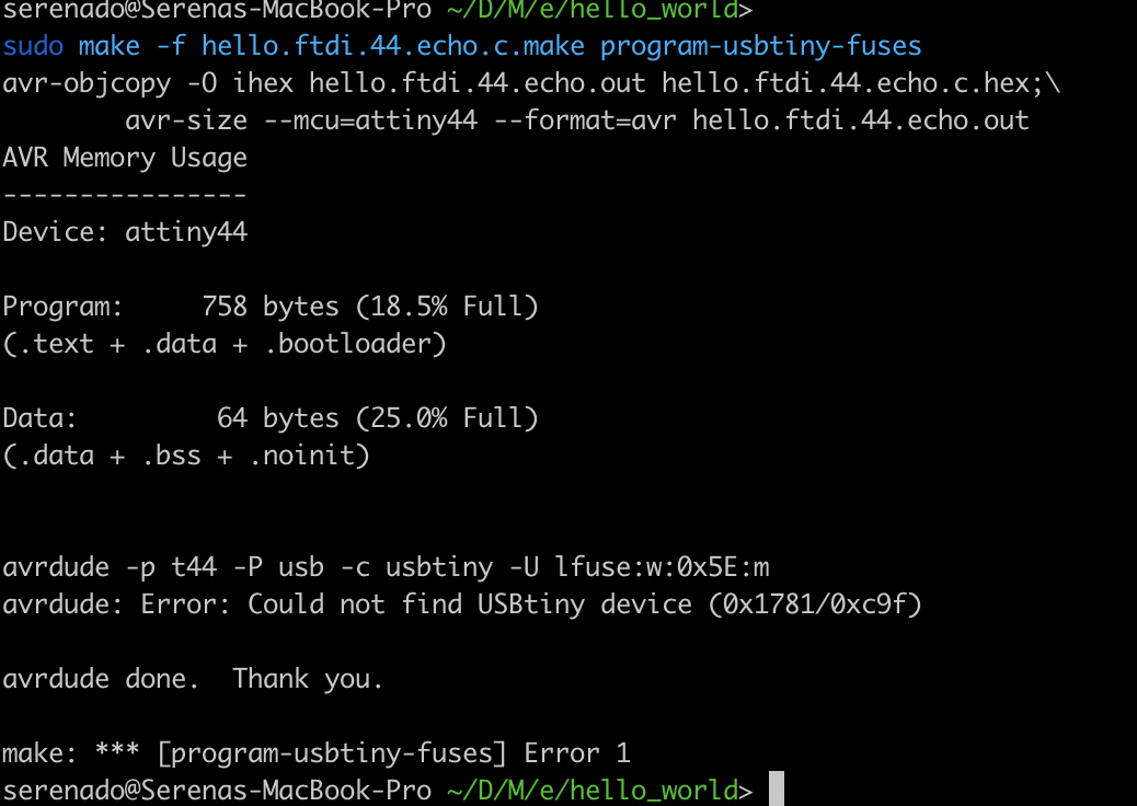
I tried programming the board using both my Macbook and my PC running Ubuntu. I had trouble getting avrdude to communicate with the programmer from my Macbook due to the error shown below so I decided to use the Arduino IDE instead to try uploading a simple blink sketch which worked.
However, the code to test serial commnunication wasn't in the form of an Arduino sketch, I decided to pull out my old laptop running Ubuntu to try uploading the sketch. I was able to program and test out term.py without too much hassle. Once I uploaded the program, I downloaded the proper FTDI drivers for my Macbook and was able to read in serial input on my Macbook as well.