Week 10: Networking and Communications
This week’s assignment is to design, build, and connect wired or wireless node(s) with network or bus addresses.
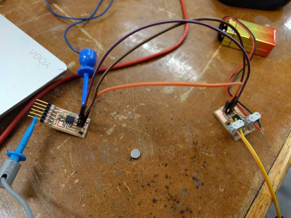
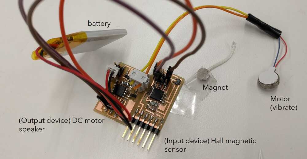
Summary: I connected using wires my input device (magnet45) to communicate with my output device (speaker45).
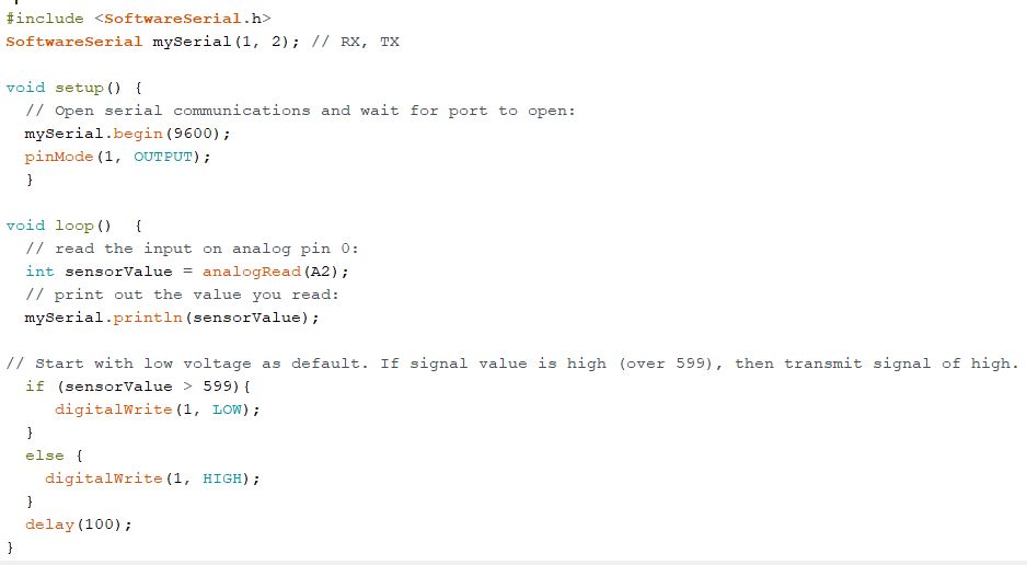
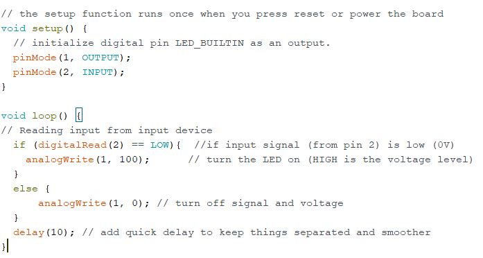
First, I programmed the boards so that when the input device senses the magnet, it sends a low voltage (0V) to the output device, which runs the motor to vibrate. Vice versa, if no signal is detected, a high voltage (5V) is sent, which turns off the motor.
Notes:
• Use Pvm to slow down motor by rapidly turning on and off. Can thus reduce vibrations.
• AnalogRead reads in input, AnalogWrite outputs. With my battery, 3V is maximum, which corresponds to 255 units. Can halve or more to reduce vibration strength.
• Using PB2 pin in output device and rerouting from IST.
• Tried using pull-up resistor, but not needed any more. No need to worry about floating point noise or voltage any more.
• Tested with multimeter to see if voltage went from 5V to 0V as expected, along with the serial monitor figures when magnet is close.
• For input device, remember to use PB1 pin to connect and plug in to output device.
• Coms9 connects serial monitor.
• I also shortened the wires between the input and output devices to save space. Use heating pads and tape to cover exposed wires so that they don't keep falling off.
Although the board works when plugged into FTDI cable, it starts burning with smoke. So I cut off one of the headers that supplies power from the FTDI cable. I can no longer charge the board only with the FTDI cable, but I can still program my board with it. The input device board was hot and burning because a 5V from FTDI was powering the 3.7 V battery, which was overcharging and heating. Fixed by cutting off the power part on the FTDI. I removed the regulator and capacitor (no longer needed because using a lighter 3.7 battery). Don’t leave battery hanging. Recharge battery as needed.
A problem is that while the output device works fine on the DC motor, it does not work well on the vibrator. I realized that the vibrator wiring is unreliable. Connecting to transistor gate will help. I’ve checked that the voltage goes from 0 to 9 V every 5 seconds.
Another problem is that the microcontroller keeps resetting for the vibrator, likely because too much power is drawn. Thus, I will add capacitors (10 mf + 1mf) to control the power and connect the 9V to ground. I will see if this makes the vibrator run as programmed. Update: not sure if this really made a difference.
The main problem was there was a tiny solder bridge between two Attiny legs. Make sure to double check board for no solder spills.
With Rob and Nathan’s help, I was able to overcome these problems and successfully connect the input and output devices. The Hall sensor in the input device communicates to the output device to vibrate when it senses magnetic force.