Week 8: Input Devices
This week's assignment is to make a microcontroller board with a sensor and measure something with it.
For my final project, I hope to create a posture corrector that vibrates when a magnet gets too close to a sensor. Thus, for this week, my goal is to create a Hall magnetic sensor that outputs different numbers depending on how close a magnet is to the Hall sensor. While an accelerometer (which detects angle) may also work, I’ll try using a magnetic field sensor because it is easier to understand and I can focus on the design.
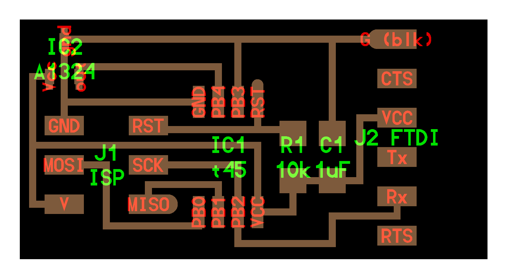
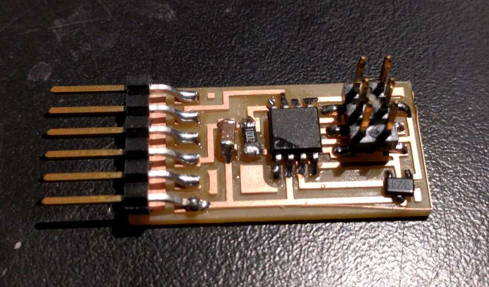
First, I made the input device board according to Neil's schematic of hello.mag.45.


Then, I installed the necessary software and drivers that work on Windows 10. For this week, I used one of the Linux computers in the lab to program my board. However, to program the board from my Windows 10 laptop, I needed these drivers and need to follow these steps:
- • USBtiny installer, which enables the USBtiny board to be read. (This may show up under Device Managers as “lib…”)
- • Coolterm: to scan serial ports and test if cable is working and connected
- • FTDI driver – VCP driver. my FTDI usb still does not work though.
- I followed the instructions here
- Install WinAVR, Adafruit drivers, upload FabISP firmware drivers into USBtiny device (ensure it’s recognized in Device Manager).
- Double check Tools to ensure correct attiny45, clock speed, etc.
- Ensure FTDI cable is inserted correctly, where the black cord (representing ground) connects throughout the board (and not into a lost area).
- Ensure the rainbow cable is oriented correctly so that green and red lights up initially.
- Under tools, click Serial Monitor for numbers to stream down the screen.
- Ensure the USB is connected well. Works fine plugged in directly on left of laptop.

To troubleshoot, use multimeter to test voltage from 0-5. Continuously send 0V if no signal. If magnet value exceeds 500 (and increase voltage above around 3), then send 5V.
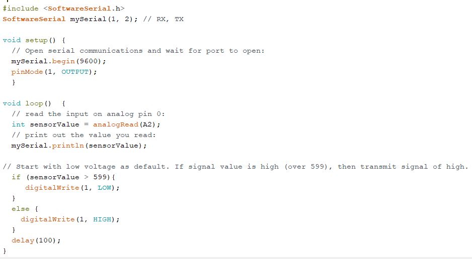
Then, I programmed the board as follows:

The default number is 512 without magnet. If the magnet is touching or some millimeters apart, then it reads 2 (or 1007 if it’s flipped over). The range fluctuates depending on how close the magnet is to the sensor. However, the numbers are sometimes imprecise and can fluctuate a lot even at the same place (especially when close to the magnet).
As the video shows, I have changed (using a magnet) the input signal to the input device.