Week 9: Output Devices
This week's assignment is to design a mold around the stock and tooling that you'll be using, mill it, and use it to cast parts.
Summary: I will make a vibrator that connects to my input device of magnetic sensor (for the posture-correcting wearable device).
For this week, I will focus on making only the output device of motor or vibrator for simplicity; afterwards, I’ll try to create one unified, compact board comprising of both input and output devices. Instead of using the DC motor board, which is more complicated as it includes two-way communication, I will make the simpler Neil’s hellospeaker.45 board, where I can replace the speaker part with the motor.
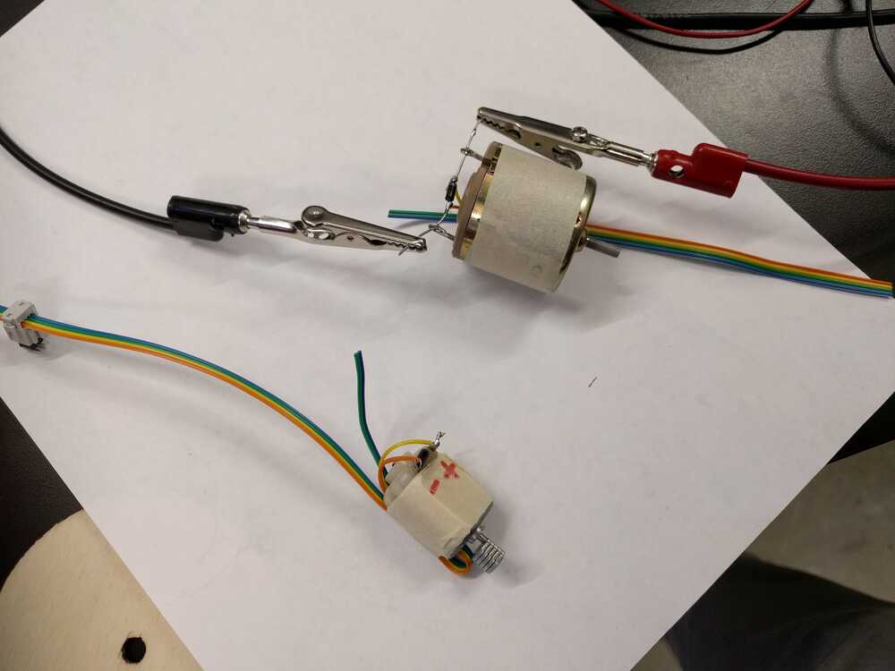
First, with Rob’s generous help, I created a mock-vibrator using a DC motor. I will replace this with DC motor with a vibrator once new shipment comes. For strength and safety, I added a (transistor?) part that I connected to a ribbon wire, which connected to a 2x2 header, which connects to my board in the J3 speaker.
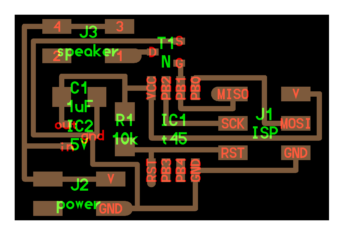
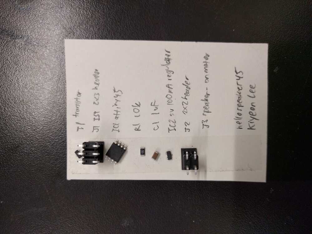
Afterwards, I designed and milled the board for hello.speaker.45, collected and soldered the parts, including the motor.
I accidentally burned part of the copper off my board, so I needed to re-mill. Also, I needed to change the tool diameter from 0.39 mm to 0.35 mm because the large diameter wasn’t able to cut the small sliver of line cut needed. After calculating, check the View to ensure all parts (especially narrow areas) are cut. Make sure to tape well.
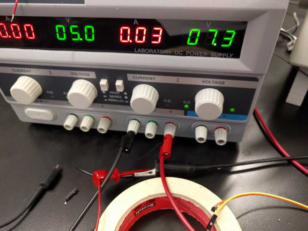
Another problem is that while the output device works fine on the DC motor, it does not work well on the vibrator. I realized that the vibrator wiring is unreliable. Connecting to transistor gate will help. I’ve checked that the voltage goes from 0 to 9 V every 5 seconds.
A problem is that the microcontroller keeps resetting for the vibrator, likely because too much power is drawn. Thus, I will add capacitors (10 mf + 1mf) to control the power and connect the 9V to ground. I will see if this makes the vibrator run as programmed. Update: not sure if this really made a difference.
The main problem was there was a tiny solder bridge between two Attiny legs. Make sure to double check board for no solder spills.