Week 11: Networking
Or, the week I met my match
This week, in preparation for my final project, I decided to prepare a board that could read a microSD card. Ultimately I think I'd like for my flex sensor to send the data collected to an SD card that can be transferred onto a computer either manually or ~potentially~ wirelessly. We'll see what I can do.
I went about this week's assignment in a little bit of a roundabout manner. What I ultimately realized is that I basically designed a board to read from a pre-fabricated board that already did what I was originally trying to do… but I'd like to take you along that journey with me.
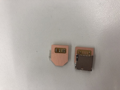
When I started the design process, the Harvard lab didn't yet have the exact type of SD card holder specified on the fab site by Neil. Instead, it had some of these bad boys:
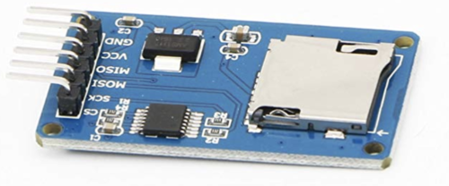
As you can see, there's already a lot of stuff on this board—the SD card holder, a microcontroller, a regulator, a variety of capicitors and resistors, and an FTDI header. Basically all of the constituent parts I was looking to put on the board of my own design. Because I lacked the individual SD card holder, I planned to just hook this entire board up to my board and ignored all of that. I needed to redesign the fab SD board so that it would work with the pins coming out of the above board. You can see that there are (from the top to bottom) CS, SCK, MOSI, MISO, VCC, and GND pins. These are the same six kinds that the stock fab board calls for! Unfortunately, they're in the wrong order. In this close up, you can see the problem:

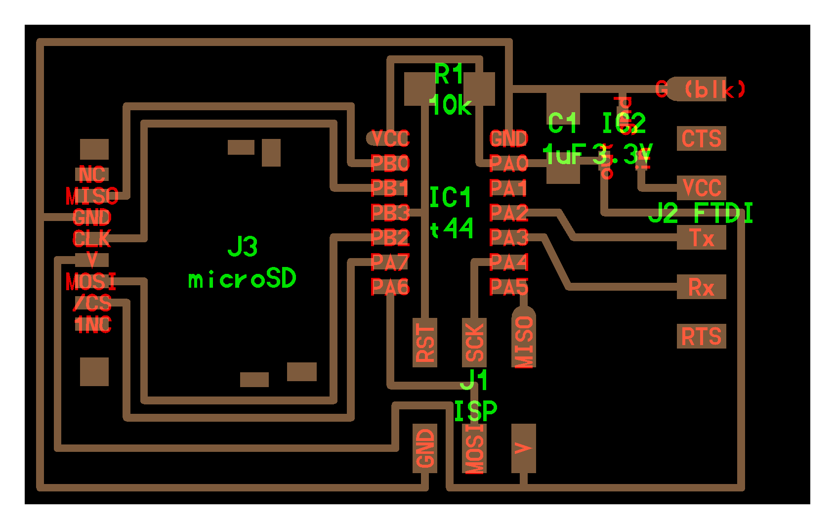
So instead of using the fab board, I needed a board with the pins in the right order:
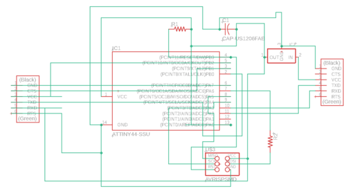
Here's the hideous schematic for my version of the board. You can see that in lieu of designing or finding a specific SD reader part for Eagle, I just used a second 6x1 pin FTDI header part/footprint (far left) and ignored the original labels. Here are the traces:
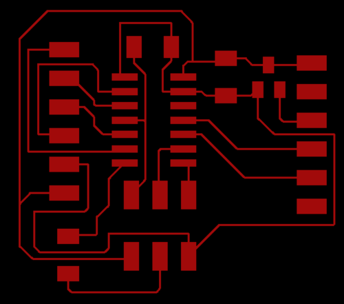
I couldn't figure out how to route everything perfectly, so you'll notice two pads in the bottom left of the image where I planned on putting a zero ohm resistor (or, like last week, just a little loop of wire—very technical stuff).
Now it was time to mill! Unfortunately as soon as I sat down at the milling machine my brain went on autopilot and I somehow managed to mill an entire copy of my board from last week before I snapped out of it and realized I was preparing the wrong thing. Highly irritating.
The milling process (when I actually milled the right board) was straightforward and painless. The traces turned out really choppy, but everything was connected where it needed to be and I smoothed it down a little bit with some 600 grit sandpaper.
The soldering process was also quite easy. The board only calls for a handful of parts:
- 1k ohm resistor
- 1 mf capacitor
- IC 3.3v regulator
- attiny44
- FTDI header
- SD card holder
And that's it!
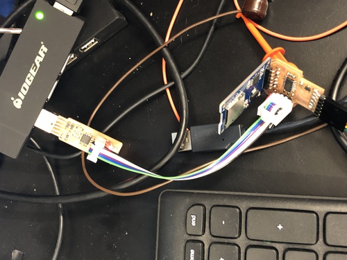
Here's my soldered board on the right, connected to the programmer and the computer. You can see that I ended up having to clip the pins from the prefabbed SD card reader to get it to sit on my board. It's at a 90 degree angle, which isn't the most elegant thing in the world (or even the second or third most elegant thing) but the board does rest on mine so there's stability. It isn't just touching via the pins!
Programming the board was painless. This is the first time I've ever had a board program on the first try, which I consider to be an absolutely massive achievement and the most satisfying thing I have ever done. You just need the right files from the site: hello.uSD.44.read.make and hello.uSD.44.read.c.
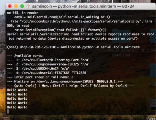
This is where I started running into trouble, but I think it's because I wasn't running the proper command. Everything should work with Neil's code if you type in sudo python -m serial.tools.miniterm /dev/ttyUSB0 19200, where /dev/ttyUSB0 points python to the appropriate serial port and 19200 sets the baudrate.
I tried doing it with term.py, but couldn't get it to work. I then assumed it was an issue with the fact that I basically had two identical SD-reading boards connected to each other, and tried to add on the proper SD card holder (which had since arrived to the lab) instead of the prefabbed board:
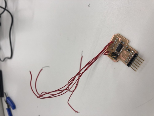
Because the pins are in a different order, I attached wires to my board so I could order the pins properly on my new breakout board:
But it quickly became a nightmare. I was using an FTDI header footprint for the pads, but the pins of the SD reader don't match up to those precisely and it was an exercize in maximum soldering frusturation. What I need need need to do is just remill a board with space for the proper SD holder and go from there.
Alright.
So that didn't work, but I also realized that I didn't necessarily need it to work in the first place. The most useful networking technology that I could implement for my final project is bluetooth. Having working bluetooth communication between my ski and my computer would free me from relying on a wire to transmit data between the two.
For bluetooth networking, I opted to use the Adafruit ESP32 Huzzah board. My plan was to connect the FTDI pins from my strain recieving board to the corresponding pins on the ESP32 (Rx/Tx) and then shoot the serial data over bluetooth to my computer. For programming the board I finally turned to Arduino.
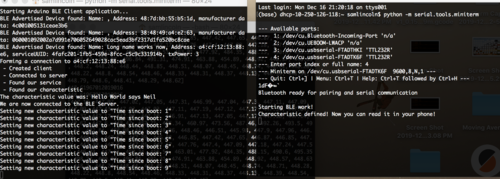
x/*Based on Neil Kolban example for IDF: https://github.com/nkolban/esp32-snippets/blob/master/cpp_utils/tests/BLE%20Tests/SampleServer.cppPorted to Arduino ESP32 by Evandro Coperciniupdates by chegewara*/#include <BLEDevice.h>#include <BLEUtils.h>#include <BLEServer.h>#include "BluetoothSerial.h"// See the following for generating UUIDs:// https://www.uuidgenerator.net/#define SERVICE_UUID "4fafc201-1fb5-459e-8fcc-c5c9c331914b"#define CHARACTERISTIC_UUID "beb5483e-36e1-4688-b7f5-ea07361b26a8"\BluetoothSerial SerialBT;void setup() {Serial.begin(9600);SerialBT.begin("ESP32");Serial.println("Starting BLE work!");BLEDevice::init("Long name works now");BLEServer *pServer = BLEDevice::createServer();BLEService *pService = pServer->createService(SERVICE_UUID);BLECharacteristic *pCharacteristic = pService->createCharacteristic(CHARACTERISTIC_UUID,BLECharacteristic::PROPERTY_READ |BLECharacteristic::PROPERTY_WRITE);pCharacteristic->setValue("Hello World says Neil");pService->start();// BLEAdvertising *pAdvertising = pServer->getAdvertising(); // this still is working for backward compatibilityBLEAdvertising *pAdvertising = BLEDevice::getAdvertising();pAdvertising->addServiceUUID(SERVICE_UUID);pAdvertising->setScanResponse(true);pAdvertising->setMinPreferred(0x06); // functions that help with iPhone connections issuepAdvertising->setMinPreferred(0x12);BLEDevice::startAdvertising();Serial.println("Characteristic defined! Now you can read it in your phone!");}void loop() {// put your main code here, to run repeatedly:delay(1000);// SerialBT.println("Hello World");if (Serial.available()) {SerialBT.print(Serial.read());}}
The default code (listed under 'examples' as soon as you add the ESP32 boards in Arduino) is everything until the void loop(), and then I put in some basic code to get it to print values over serial. It recieves serial data from the strain recieving board then prints it over "SerialBT" to my computer. I tried it first with printing "hello world," and it worked!
I even connected an ESP32 to another ESP32, one on the ski and one to my computer, and got them to connect to each other:
 Unfortunately, I couldn't get these boards to communicate serial :(
Luckily, I only need one to work for my final project! See my final project documentation for information on the implementation with the ski.