Introduction:
A flowerpot that moves as it lives
Inspiration
Big Idea
I want to create a flowerpot that can react to the envoirnment around it in some way. We know that plants move as they grow, they follow light, and they evolve and move on a cellular level. They are generally static to us, however, and I wanted to create some way to represent their inner real workings.
Whats Out There
Of course, there are many flowerpots, but I found nothing similar to a breathing flowerpot. I saw concept art of flowerpots that could move around (like on a car), but nothing that would actuate the actual flowers themselves.
I also stumbled upon some cool linear actuating mechanisms that I could try to replicate, and interesting patterns that react to music.
I looked into the idea of treating my flower pot as a "starter" pot, where smaller plants and seeds could begin to grow. The stimulation would be akin to stimulating a young baby!
Ideation
A flowerpot with small compartments that control plants in a mesh. Reacts to music, sunlight, etc.
Pod Design
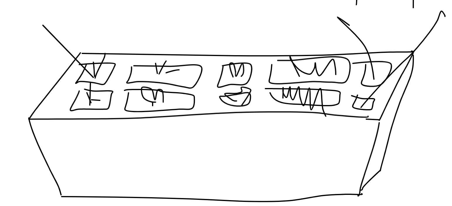
I sketched some pod designs for each of the sub flower pots.
The idea is that each pod will have a layer of plywood around it, with cut slots, to guide bearings. This should let it move up and down smoothly, while minimizing the distance between pods.
Above is the array of bearings.
Sensory Ideas
Output Device Ideas
One idea for moving the pods is to use a stepper motor with a CAM shaft attached. This allows for quiet operation, smooth up and down movement, and simple manufacturing.
MANUFACTURING
Scope
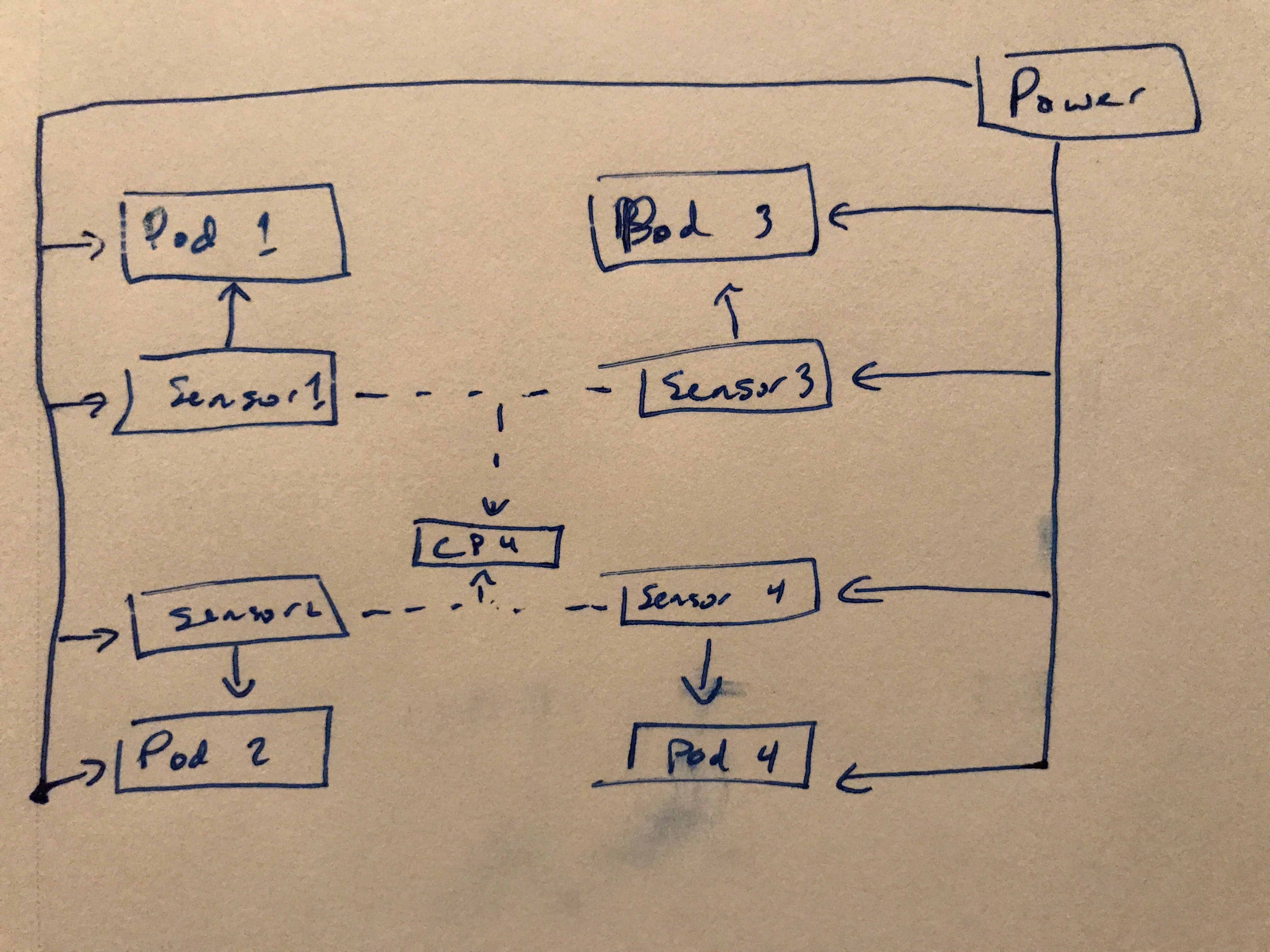
11/12 - I decided that I want my scope to be as such: have four pods that would move up and down. They will be accompanied by their own audio sensors, and will pulse with a frequency that is a function of the volume of sound around it. A stretch goal is to sync them up such that each pod is communicating with eachother, and they pulse in a direction (from where the music is coming).
The block diagram can be found below.
Pods
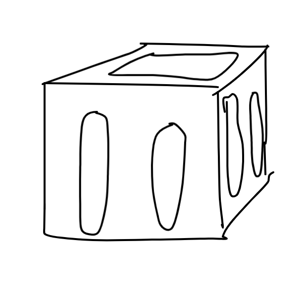
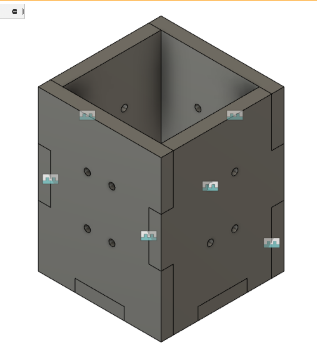
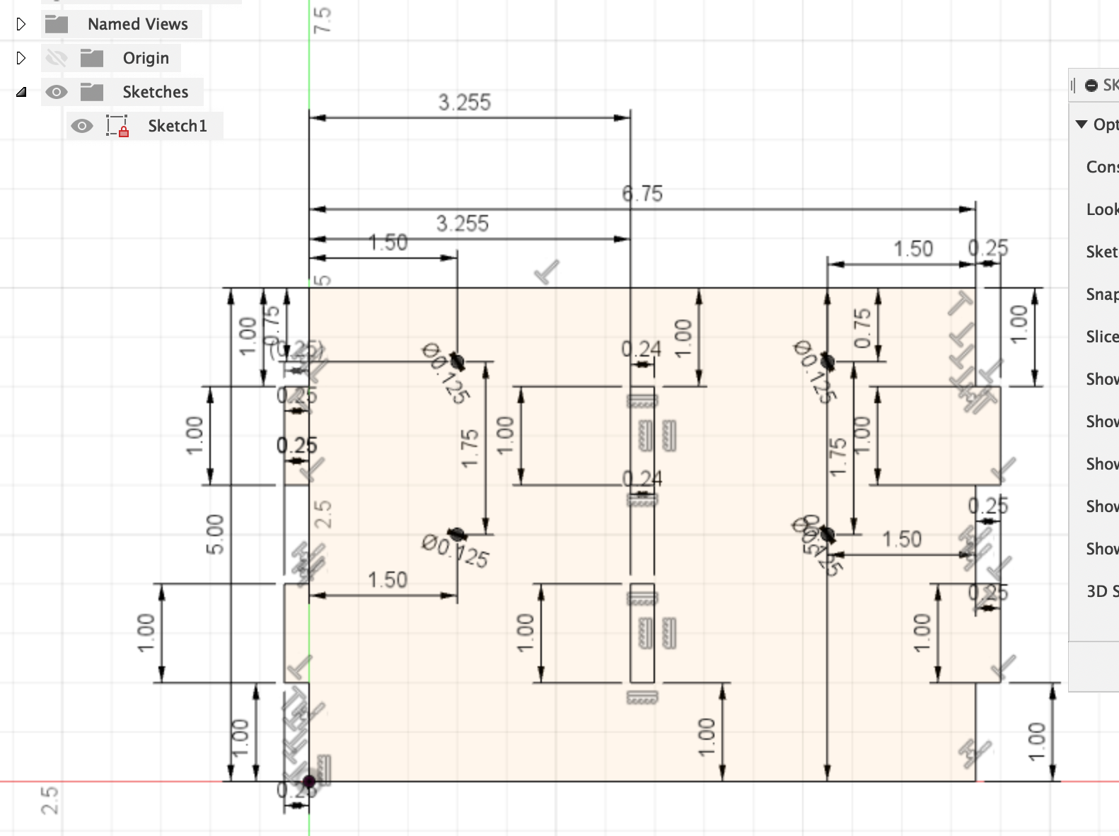
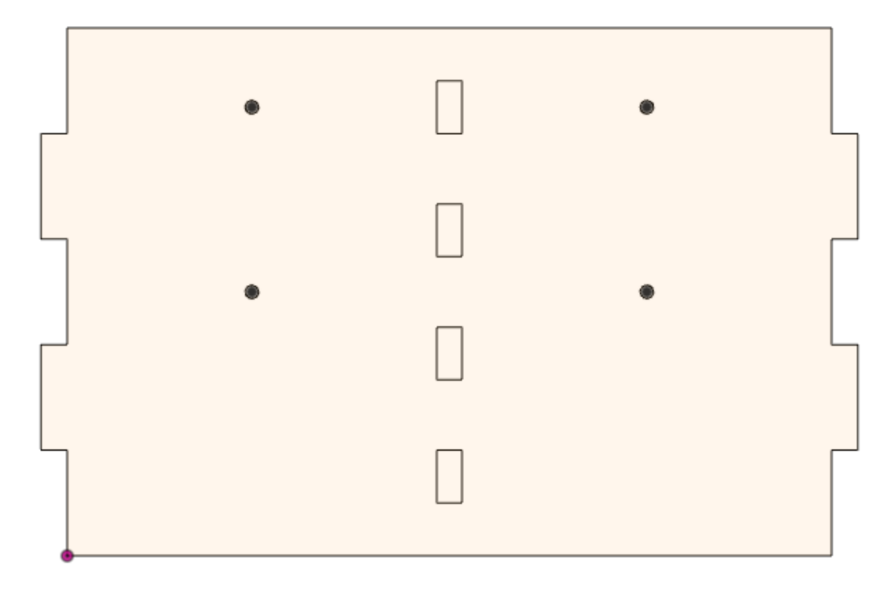
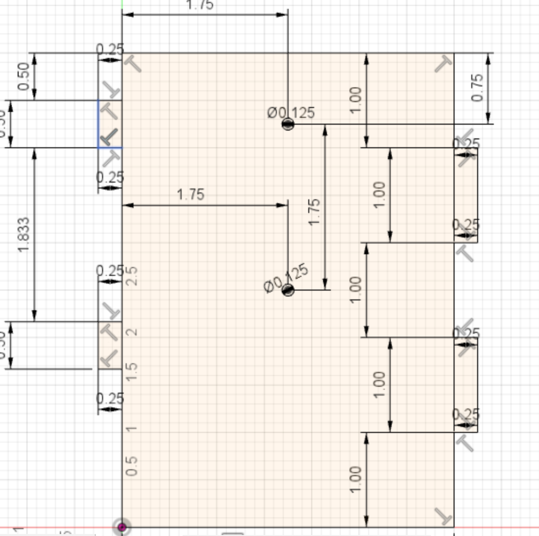
11/13 - Using my design from the Ideation phase, I began to design the pods in CAD. I based my measurements off of starter plant kits, where small seeds are given degradable soil holders. From there I made the inside boxes. I plan on using wood glue to put all the peices together, which is why I designed around the tabbed models. I also added holes for the slides to reside in.
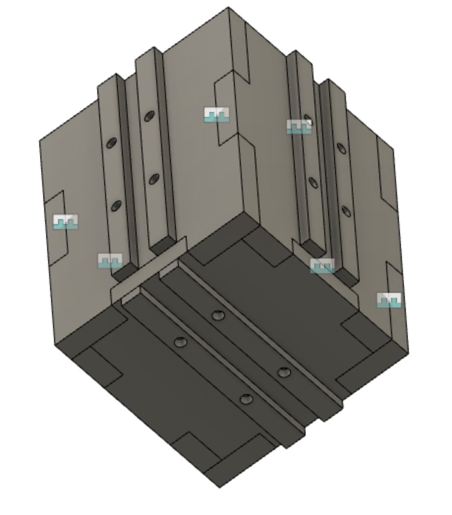
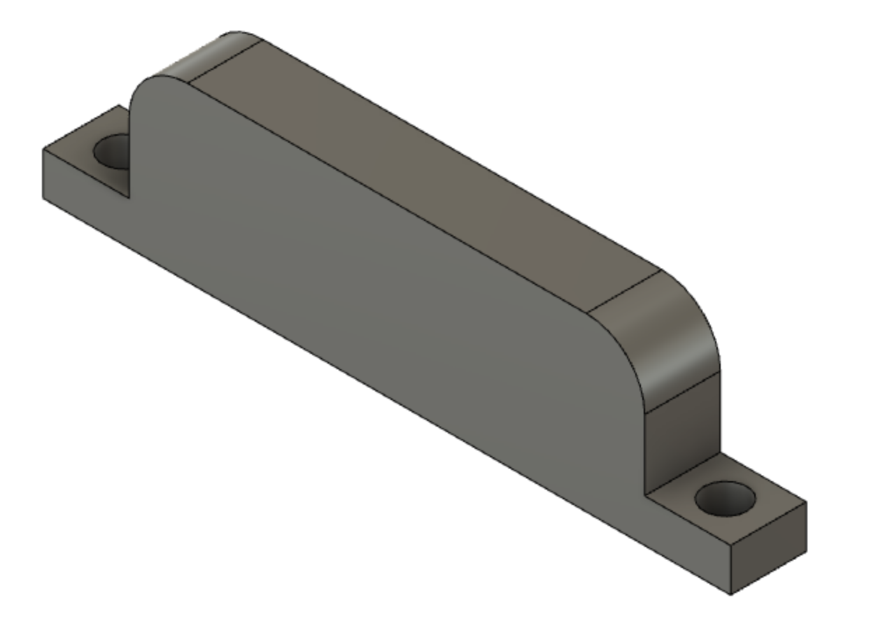
The side rails were the next step. I'm going to try using wood slots along the outside of my pods. I plan on 3D printing a few slider peieces to act as vertical bearings of a sort. I hope that I don't have problems with the friction between the plastic and the wooden slides, but this will make manufacturing very easy, so I'll try it first. To keep things simple, I'm doing everything with 1/4" wood.
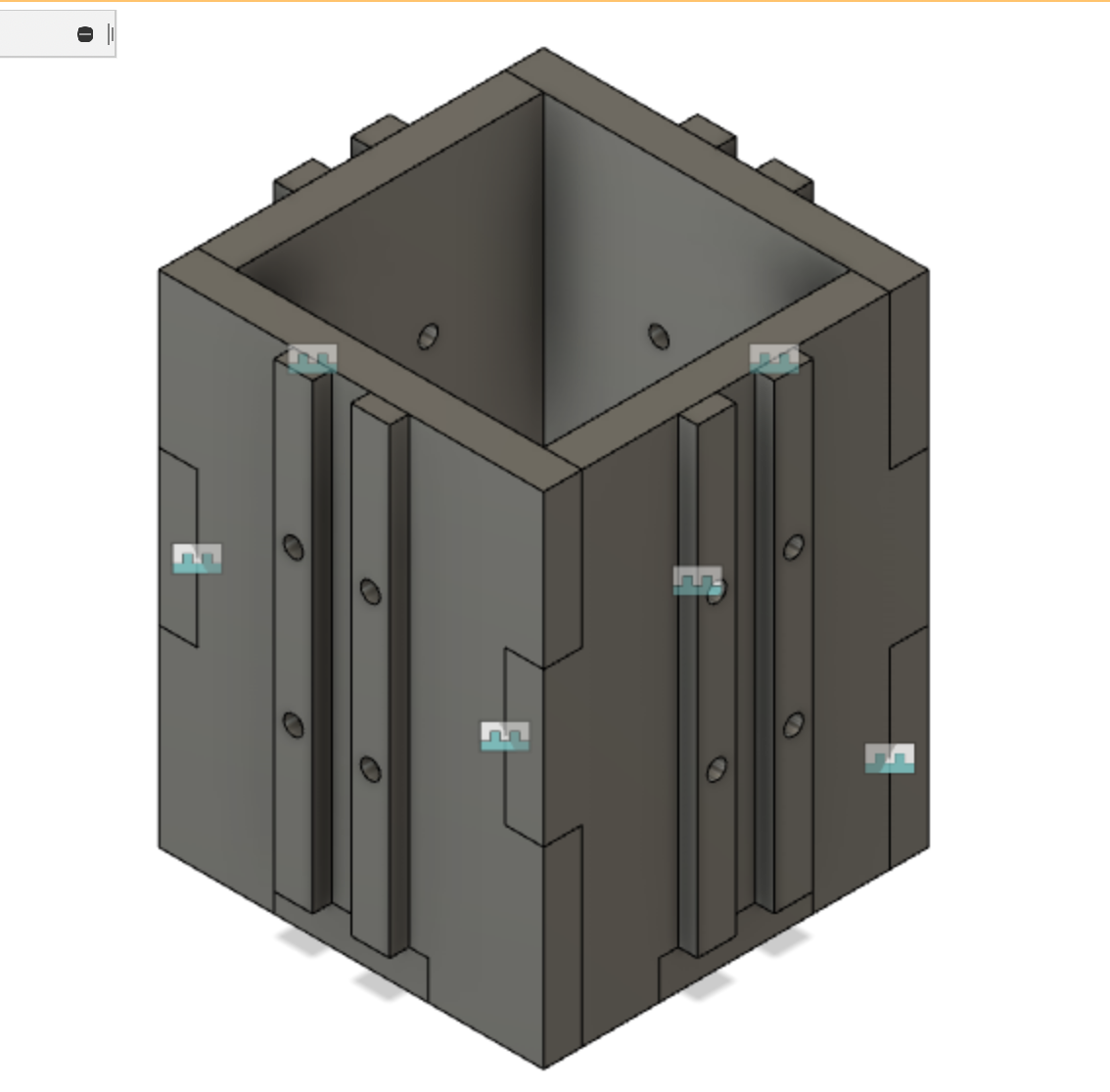
Of course, I need to do the same for the CAM mechanism on the bottom. Again, I'll keep wooden slots to guide/house the CAM mechanism, and I'll design the 3D CAM part later. For now, I'll add the same slots to the bottom of my pod.
I'll cut them out tomorrow, if I get a chance!
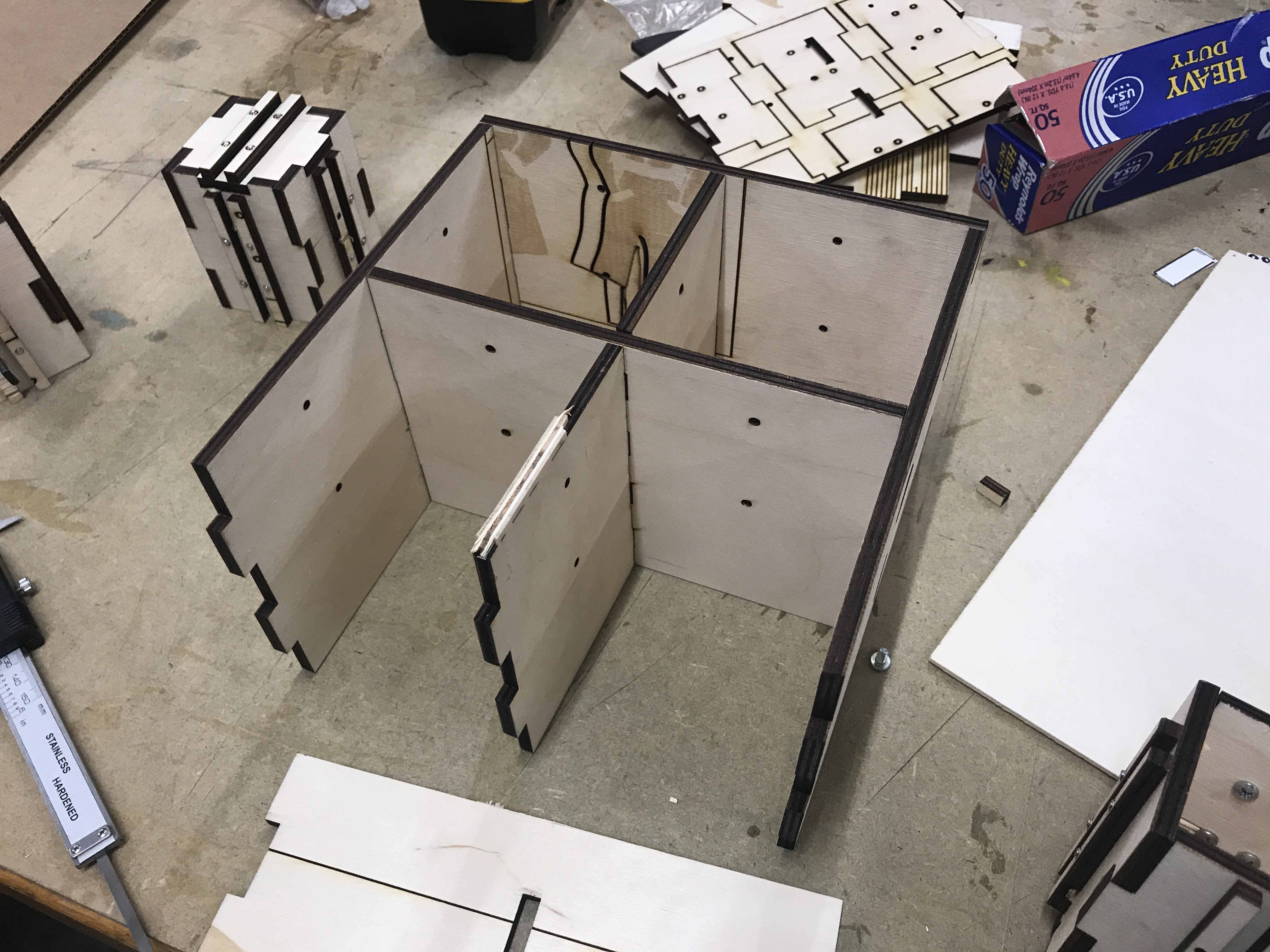
11/15 - I'm cutting things out now. My first cut, as can be seen below, did not cut all the way through the wood. I completely forgot to calibrate the Z of the cutter. I'm rusty! After fixing that, things got going.
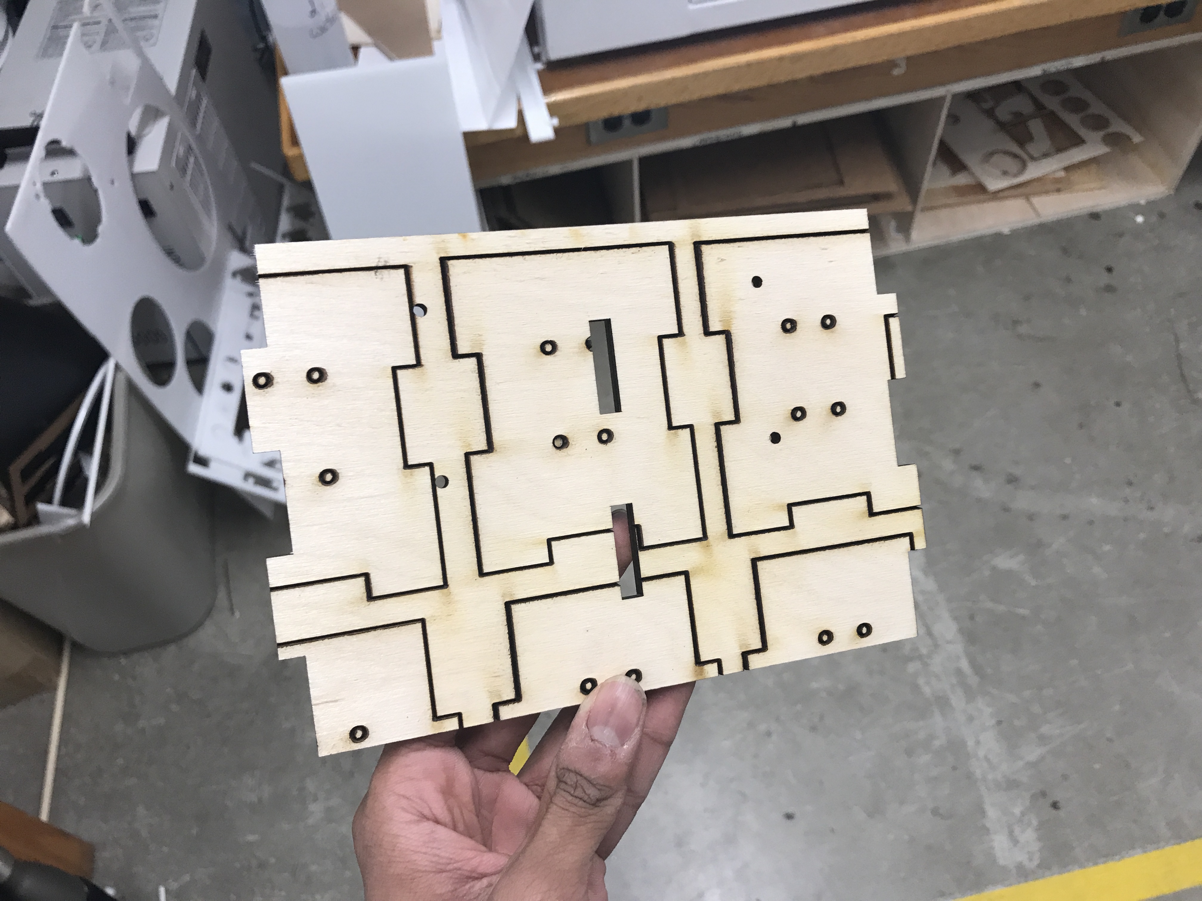
Thankfully, I could reuse the same wood for other parts, so nothing was wasted.
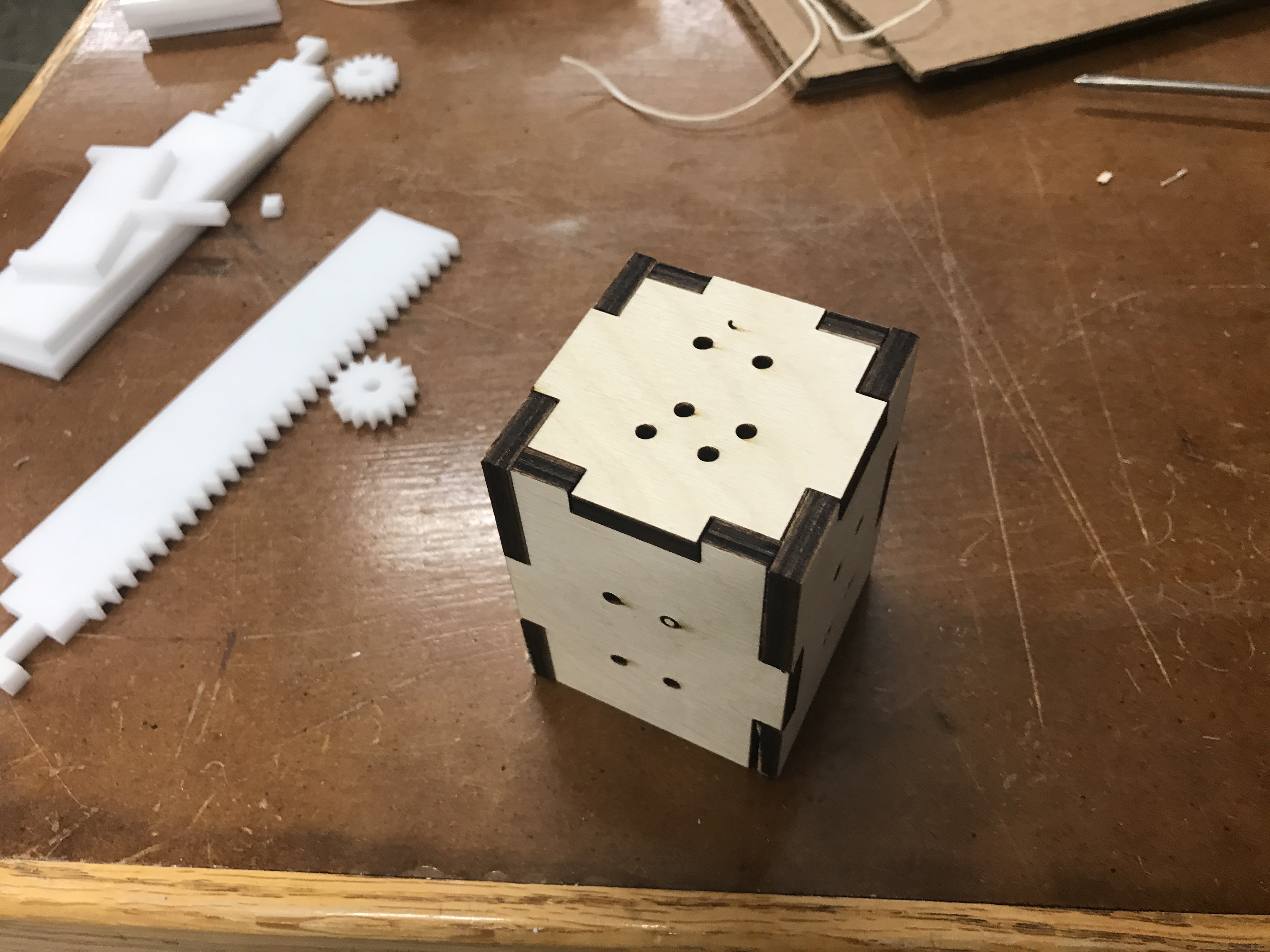
Now I could put it all together, and let the glue set. I'm going to do that tonight, and leave it over night. I'll cut and screw in the slides at a later date.
Electronics
11/15 - As I wait for the glue to set, I'm going to take an electronics break, by designing my first circuit. This had to be a simple stepper motor circuit, and I largely based mine off of the bipolar stepper motor circuit on the CBA site. It should get the job done. I'm going to leave a spot to solder a jumper (to an Analog port). This way, I can keep my sound sensor circuit separate, and closer to the noise it should be collecting.

Below, I'll talk about where I messed up with this circuit.
Pod Housing
11/18 - Ok, I haven't worked on too much in the last couple of days. Let's get cracking on the actual pot part of this project. Now that all my pods are measured out, I can complete the exterior. The important part is to maintain the correct distances between my slide/bearings. Speaking of that, I'll design those first.
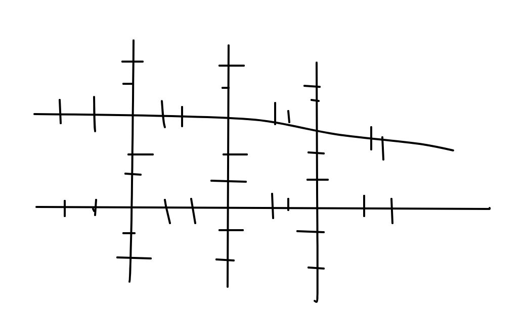
I started by thinking of two round slides like shown below:
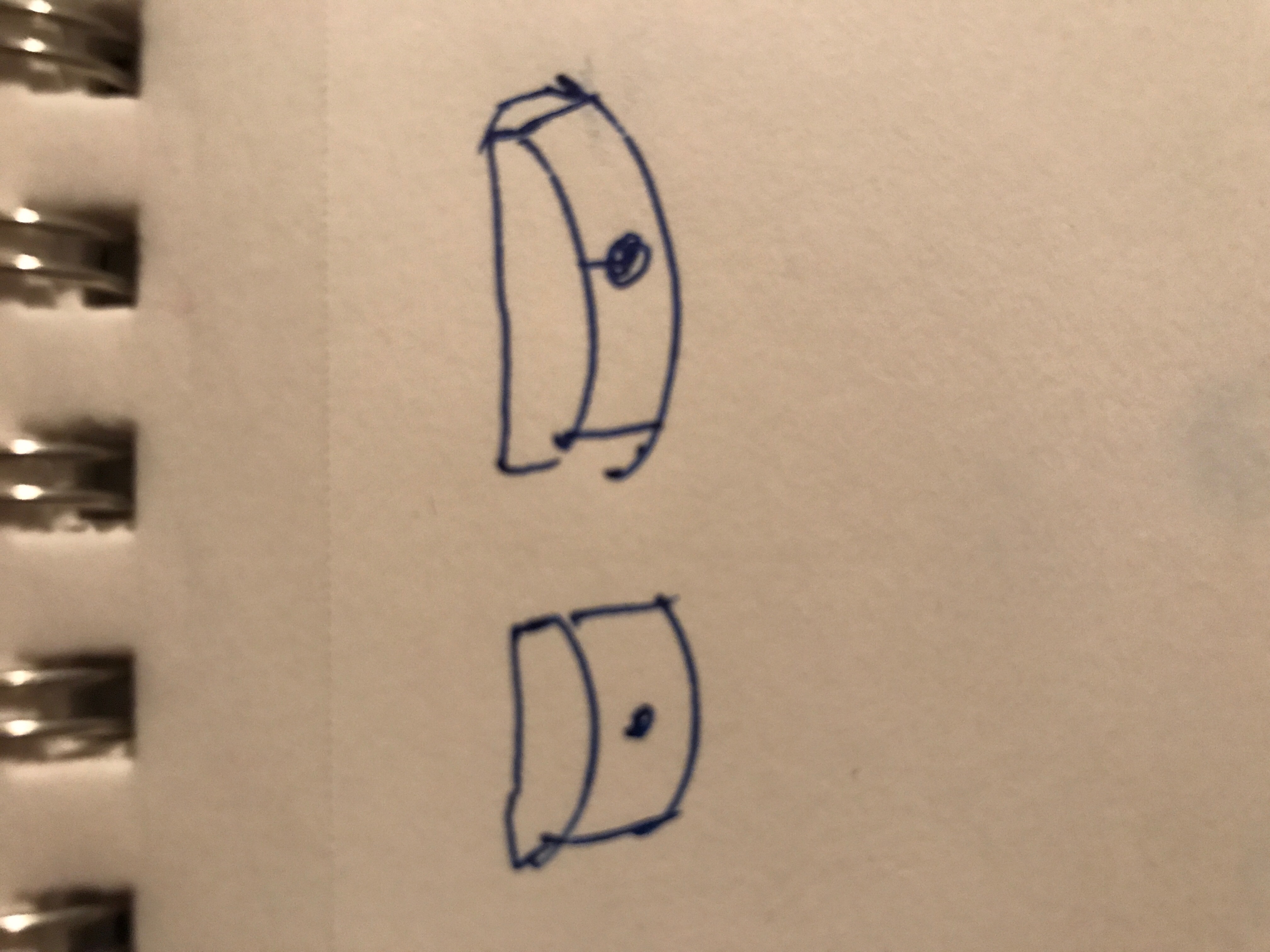
Before CADding that, I realized it would be far simpler to make one large one, that would give it lateral stability. I CADded that instead.
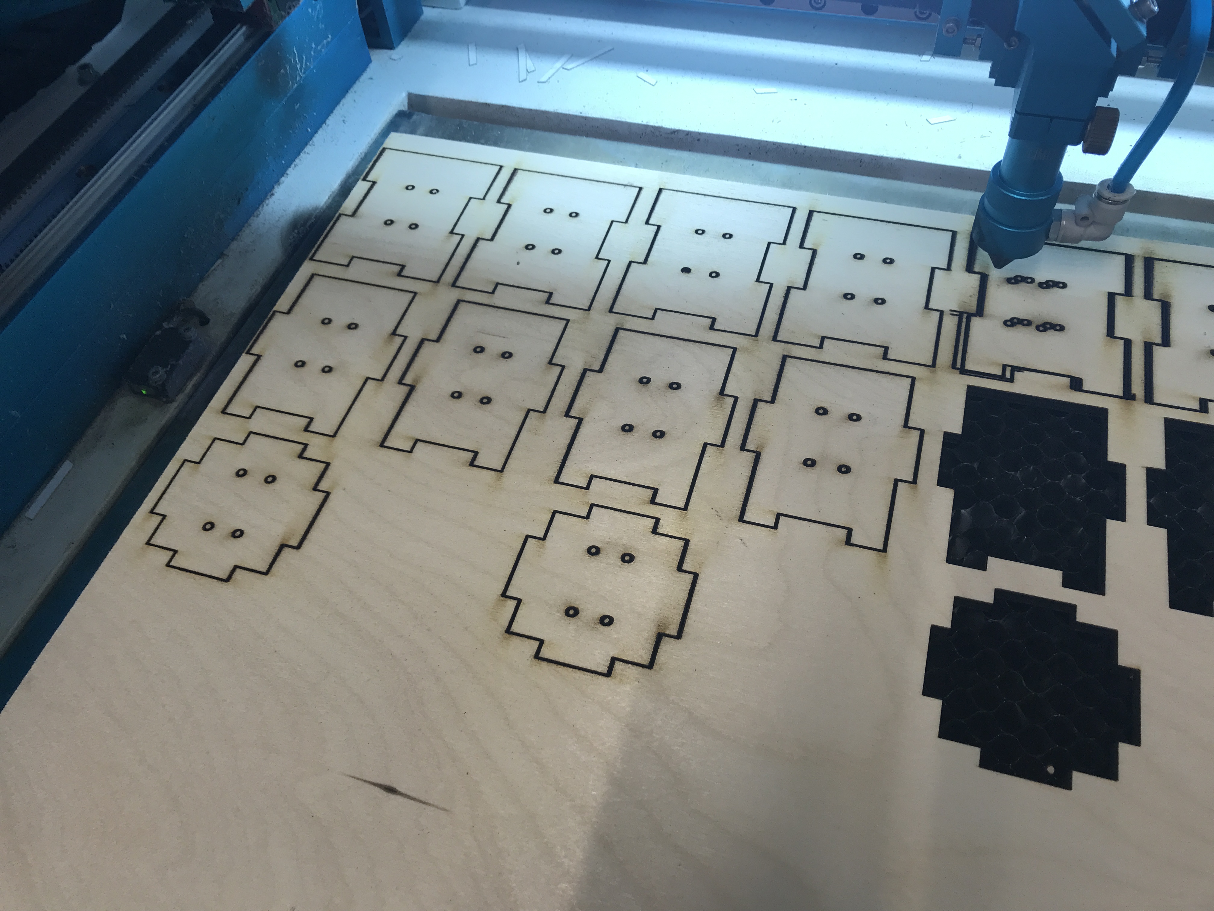
I began 3D printing these guys. I'm going to try to do all 16 in one go.
This gives me a baseline with which to structure my housing. I know I need four walls around each pod, and that the slides need to be right in the middle. Again, I will use the tabbed method of connecting them together, complete with wood glue.
I also therefore need 5 different peieces. Two fronts, two sides, an inner peice, and two (different) inner side peices.
I sketched up each peice, complete with slots to attach eachother to, and holes for the slides. Below is the front.
Below is the middle.
And below is one of the side peices.
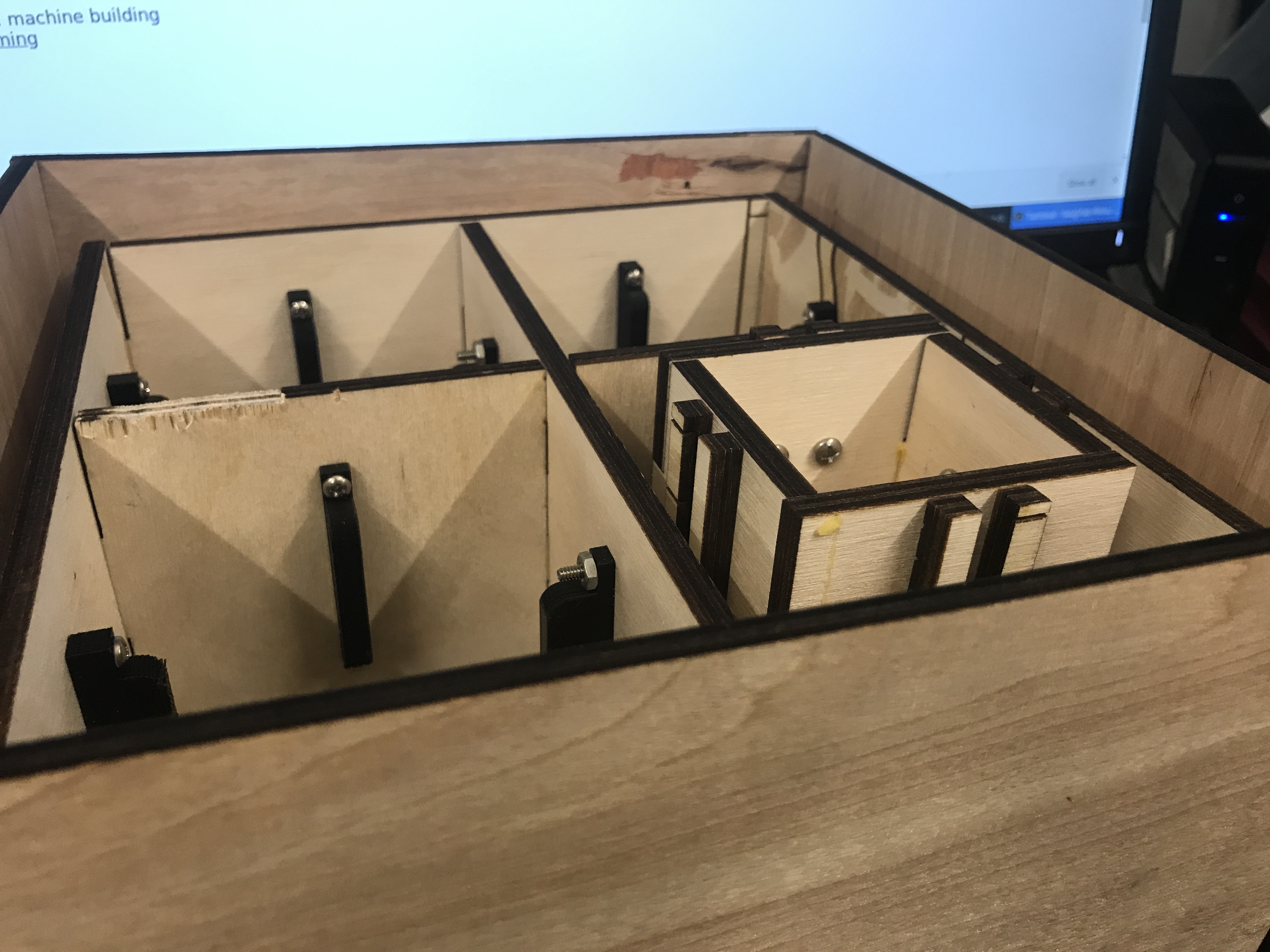
I laser cut them all, and assembled them together. Something didn't look right.

I forgot the thickness of the slide itself! Everything is .25" too small, and the walls are too close to one another. Back to the drawing board. At the very least, its an easy fix.
After redoing all my sketches, I laser cut everything again, and got the correct sizing. Before doing this, I also added in holes for the motors to mount to, after realizing that I could package it all together like that
Now to wait for the 3d prints to finish up and I can put the slides in.
Electronics
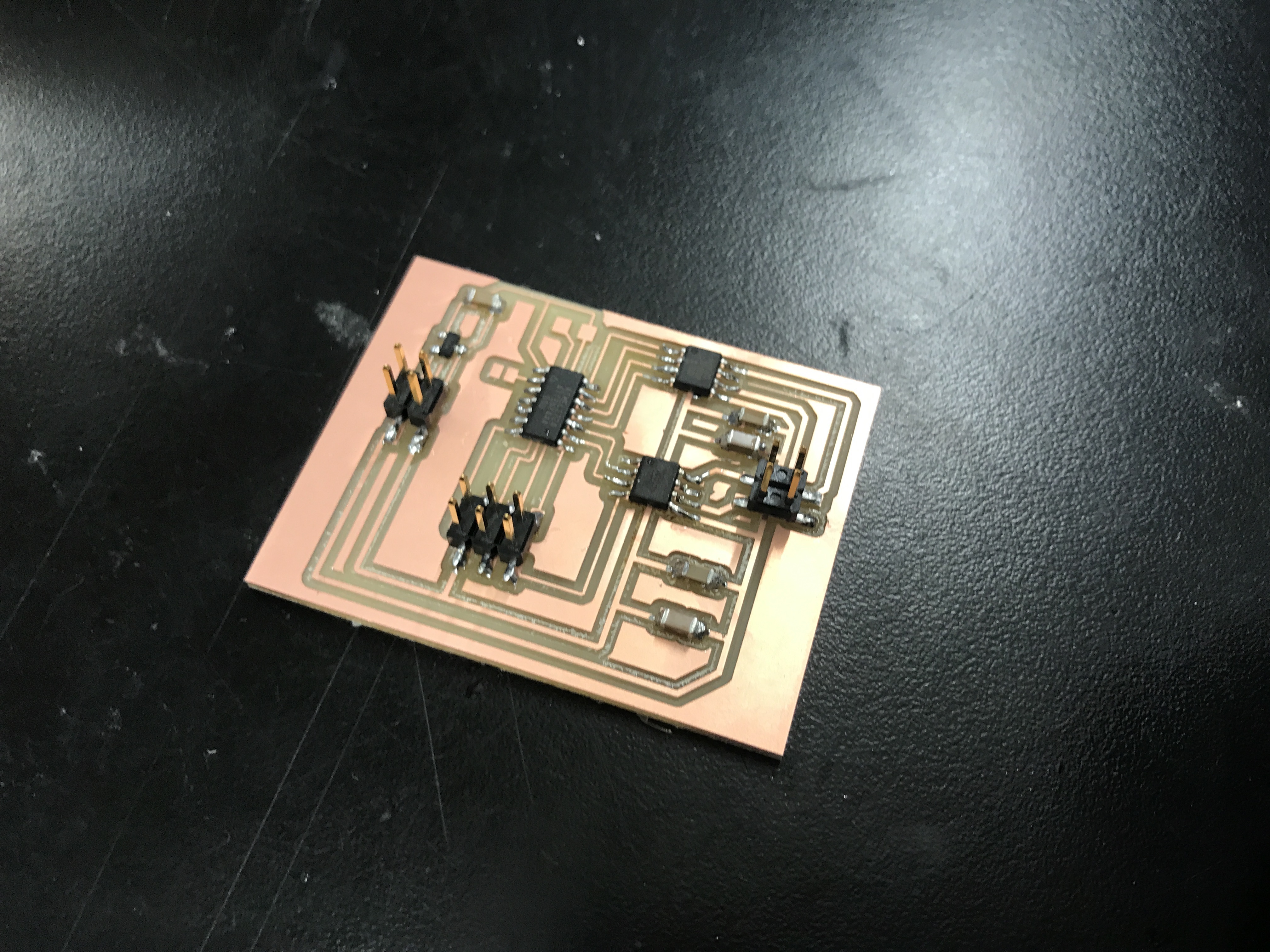
11/20 - Well, I cut out the circuit I designed above, and soldered it to my liking. This is what it came out to look like:
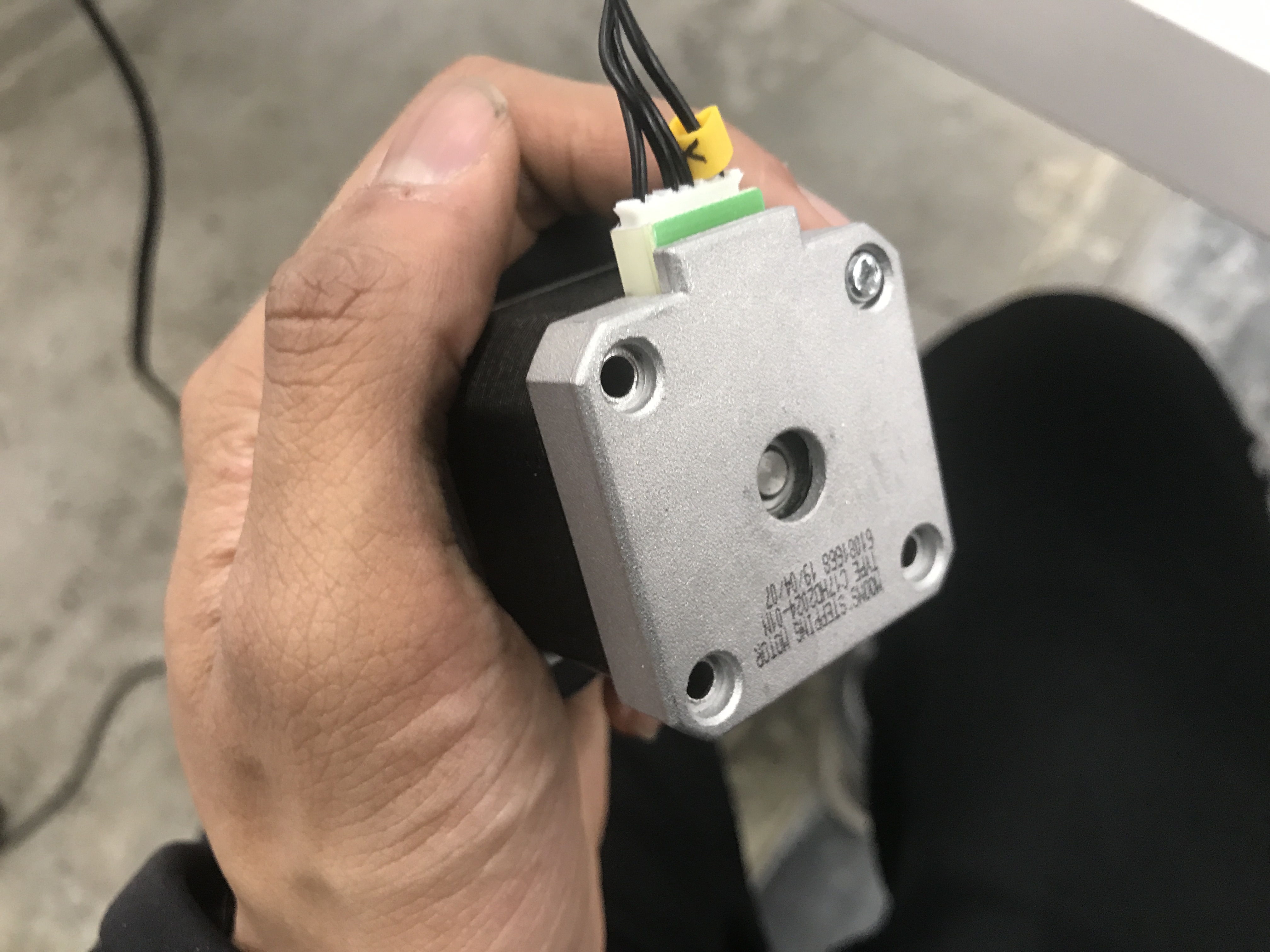
Fun side note at this point: I don't actually have 4 stepper motors. I'm taking apart a 3D printer I have for it's stepper motors, and have 2 with the D Shaft I need. However, I'm like 95% sure its a standard bipolar motor, and that this circuit will get it to work. This is the motor:
After downloading the sample code off of the website, I was pleased to see it work! The motor spun. From there, I experimented with different speed settings, and got the motor to go in a circle with variable speeds. I was pleased with that.
However, I then realized that the pin I had made my connection to was not actually an analog input pin. I couldn't use it for my intended purpose. I remade my board and connected it to PA7 instead of PB0. Should've read the datasheet closer!
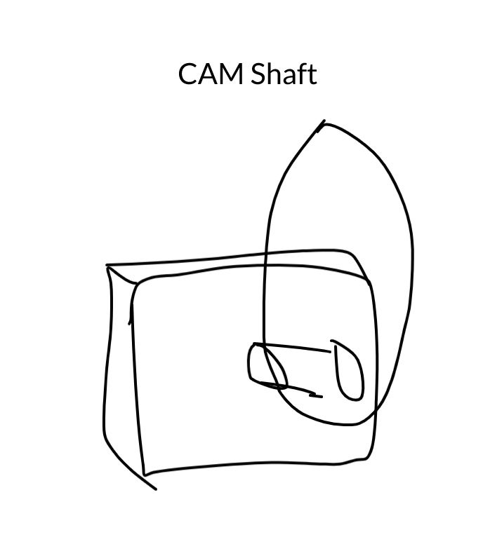
CAM
12/1- Today I'm working on the CAM shaft that my stepper motor will attach to. I'm going to make a few variants so that I can try out different throws for how much my plants are actuating. It'll be a simple ellipse with a D shaped port to press fit onto the motor.
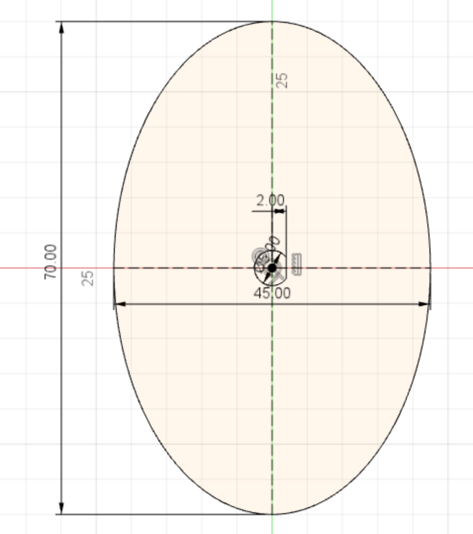
I'll get these going on the 3D printer.
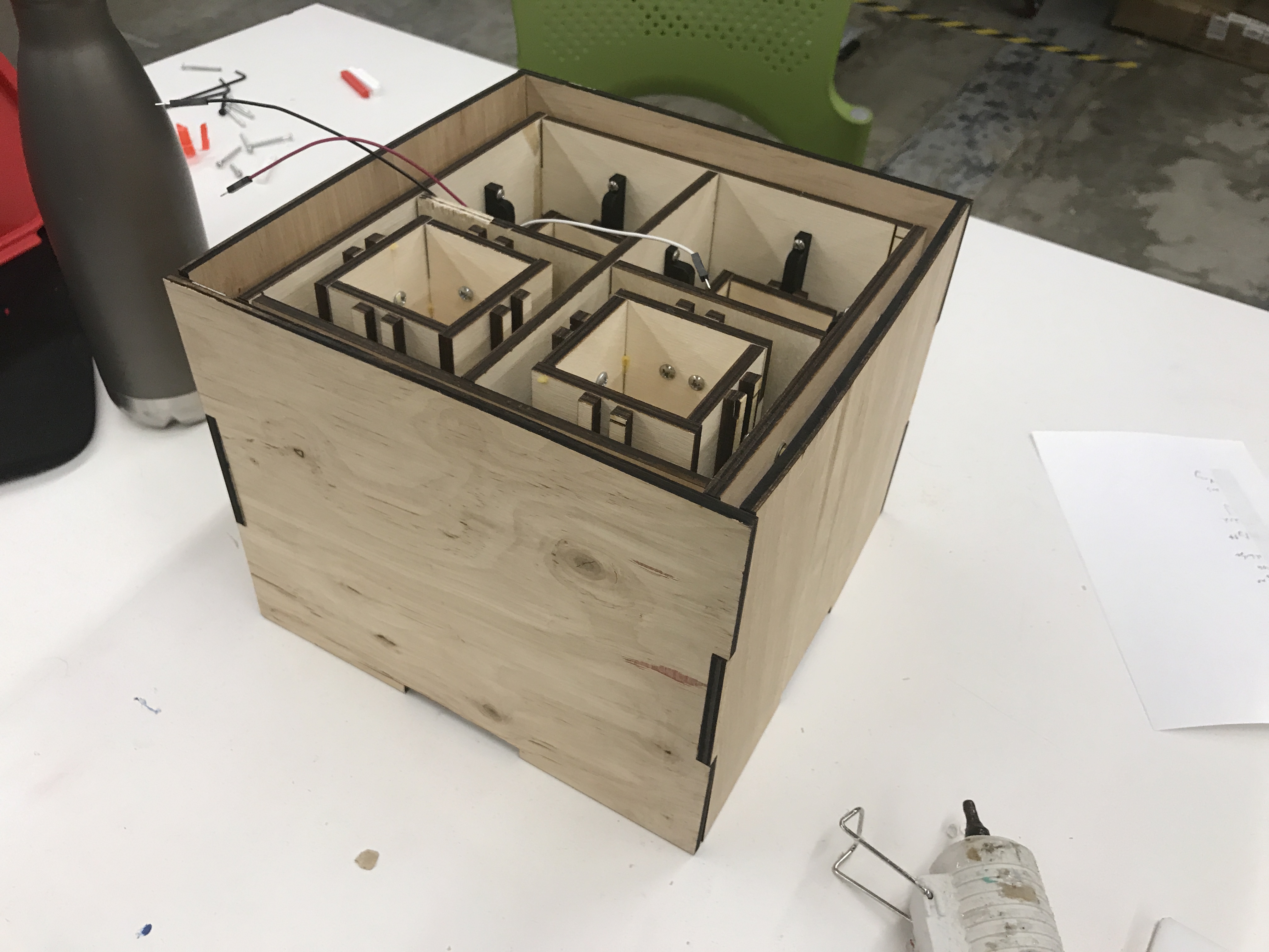
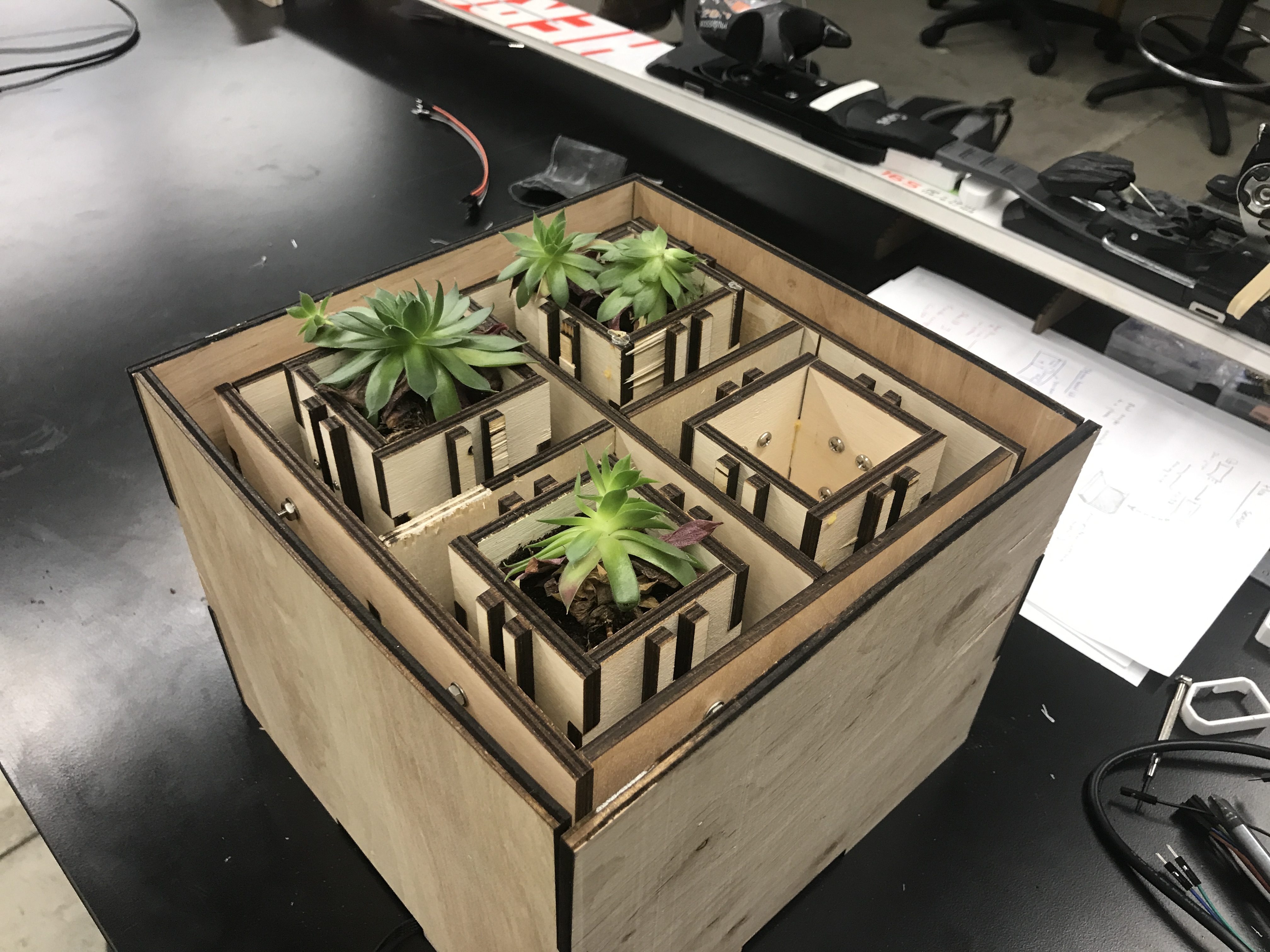
The slides came in! I've screwed them all together. Things are looking good, and the pods slide around well.
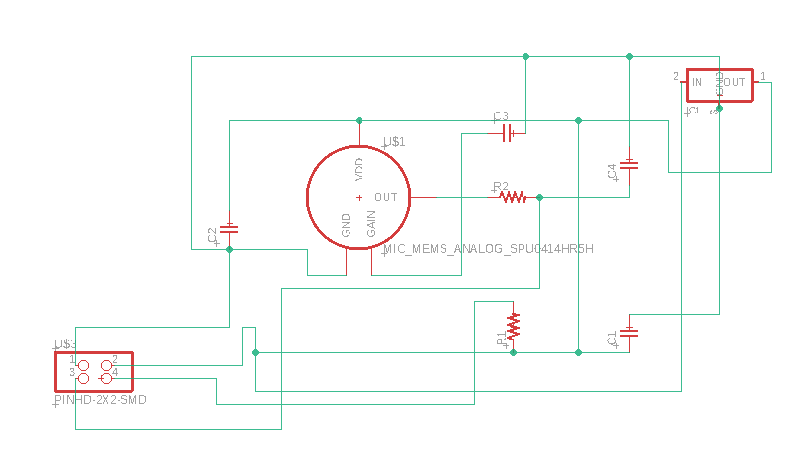
Electronics - Sound
12/5 - Now for the sound part of my electronics. I'm going to begin with a modified version of the MEMs microphone circuit. I just want to capture the analog signal. Using Robs advice, I had already made all my stepper motor logic operate at 3.3V, so that I could use the same power for my MEMs circuit. This was what I had drawn up for my sound sensor.
I cut, and soldered it next.
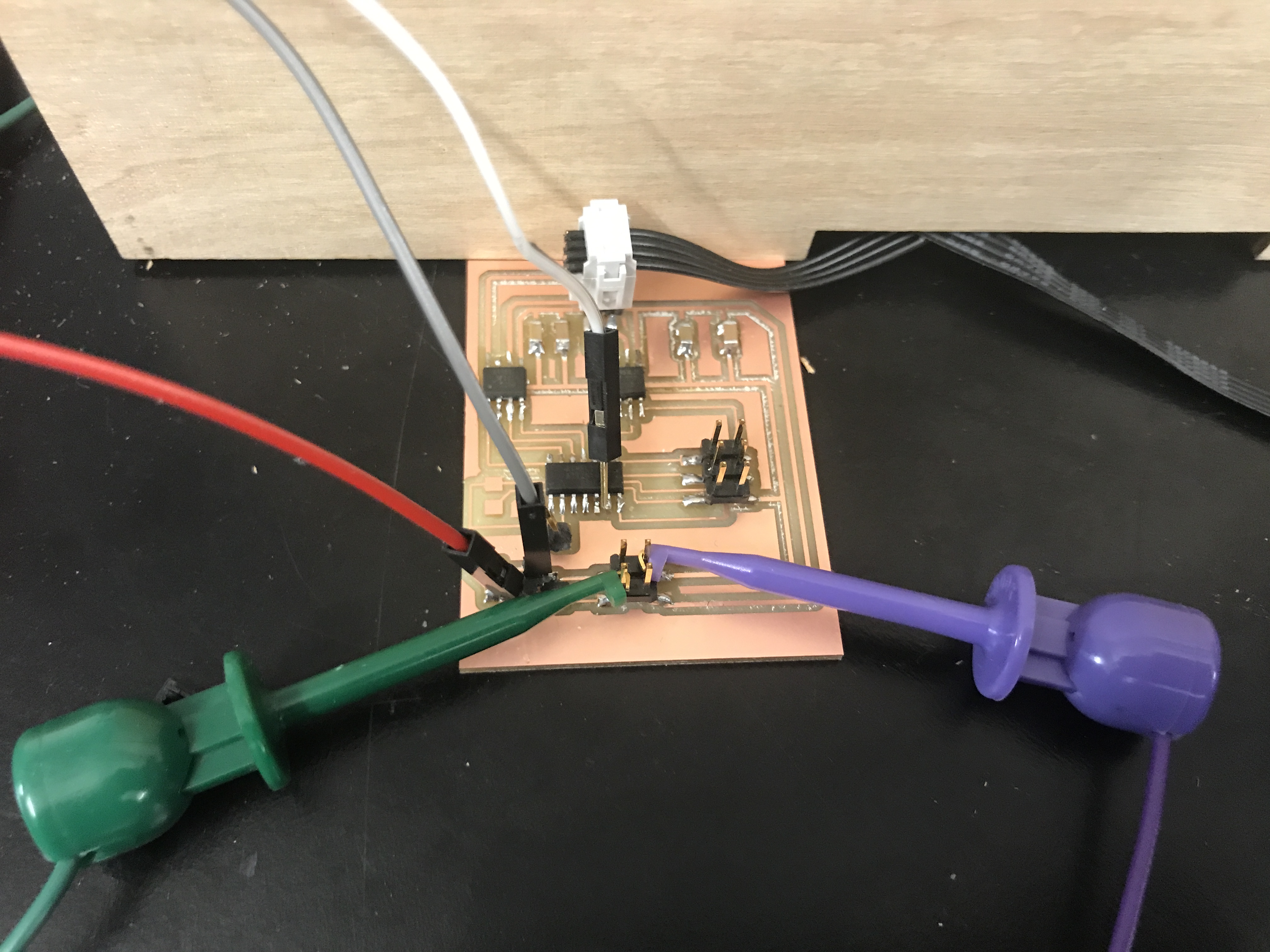
Then I hit a brick wall. I just couldn't get any reading of the sensor. I'm not sure if it's a short or something is just wrong with my circuit. I double checked everything to ensure the correct voltage levels were being sent, but I couldn't identify the problem. I'll get back to this.
Pot Housing
I used the following website to make a simple case for the outside of the entire mechanism: https://en.makercase.com/
This would hide the screws and everything from the front, and make it look clean from the outside.
Electronics - Hail Mary
Time is winding down, and I cannot figure out anything about this MEMs circuit. I'm clearly not setting something correct, and the microphone is not even being prompted to send a serial signal. Because I cannot figure this out, I'm going to pivot to a different type of microphone. Here are my attempts at debugging.
I decided to cut out the exact circuit for the Electret mic from the CBA site. The idea here is that I would do all my computation on the Attiny44 there, and send a single bit to the input pin on the at45 that controls the stepper. I'll have two preset speeds, one for the presense of music, and one for the alternative.
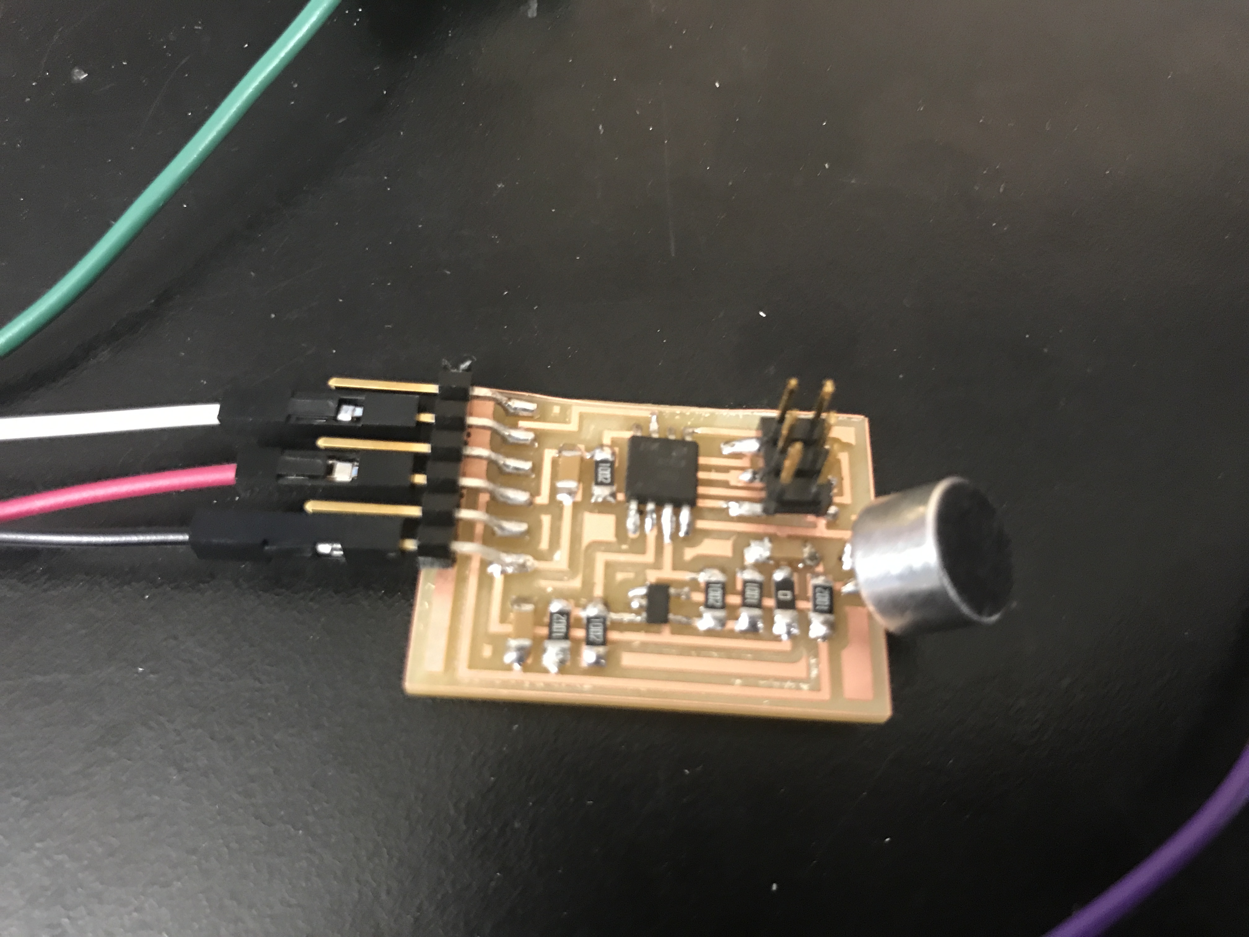
It took a lot of calibrating, but it works! I think that the calibration enviornment required is too perfect, and I'd be suprised if it worked tomorrow at the showcase.
Final
And here is the final product!
A link to my video: https://youtu.be/Thg0IgiJNo0
A video of it working: https://youtu.be/nro91ZceJYo