Mother's Embrace
Week 4
Imagine... If you could meet your loved ones remotely!
Here's me and mom from early 2019.

What does it do?
This project is a conceptual prototype using soft robotics to demonstrate touching a loved one who are away.
I planned this project so I can feel closer to my Mother who lives miles away. Due to COVID and a huge surge in India, things are rather worrisome at home. So I conceptualised a device that allows both of us to to feel closer. There are a couple considertaions that went behind the intial design:
1. My mother is immunocomprised. So she cannon get vaccinated. That is a rather scary thought but a reality nevertheless. So I considered a device that can be used for a long time. It is imperative that the device doesn't create a task but can be embedded in our everyday life.
2. I didn't want to build another app. I think a lot of apps like HeyTell, TouchNote are great but puts the onus on the users to start a conversation or action. Whereas, I wanted to do something that lives in the periphery.


Given our world today, hit by Covid, I thought it could be useful to help people feel each others' presence remotely. Of course, no amount of technology can substitute actual human touch but one can try to mitigate the difference.

The question begets: How do I achieve this?
I had to break down what it means to materialize my imagination, conceptually. When embracing another human being, you exchange body touch. When I close my eyes and try to imagine someone I love close to me, I imagine remembering how it feels to touch them.
What is human touch?
Broken down tangibly, human touch is 3 things: 1. Body Temperature. 2. Body Pressure. 3. Pulse (sometimes). To recreate the embrace of another human hand, I set out to use these two metrics to build my prototype. When I first started talking to Anthony and Premila (TAs) about my project, I didn’t know how many sleepless nights I was signing up for.
What are the ways to simulate body weight and warmth?
Brainstorm:
I focused on what makes physical touch special, in this case with my Mum. It is impoprtant through my prototype, I am able to recreate the sense of touch of a person. So I considered a couple of options to recreate a pulsation:
Something that is connected to the hand and pumps at different pressure
Maybe circulate the water
Pulse - pick it high, when it slows down so it would feel like a pulse
Use soft robotics to inflate a glove so it would feel like someone is holding a glove to give the feeling of being held.
Use water to pump or substitute it with oil which has lower specific heat.

Who's done what beforehand
Inspiration
There are a tons of work being done in this direction. It is an important topic that a lot of artists and researchers have explored in different ways. Here is a list of few references that excited me:
Link: Softness, Warmth, and Responsiveness Improve Robot Hugs
Link: Soft robots detect human touch using camera and shadows
Link: Soft Robotic Arm
Each of these methods used different ways to build the prototypes - playing with different surfaces, motor movement, responsiveness and warmth, material consideration especially in relation to touch but also protecting the equipment inside and finally, detecting human movement for reciprocity.
What did you design?
Finally, I designed a system to simulate human touch remotely using body weight aka pressure.
Broken down to its bares, it would be a increased pressure and increased temperature. The problem statement started becoming clearer from this point onward.I started researching ways in which I could play with pressure and temperature fluctuations. To this end, I explored various ways to achieve control of the elements.
I focused on a small area to prototype a solution! I imagined prototyping a wearable solution.

TECHNICAL DETAILS
For the proof of concept, through my first prototype, I planned to experiment with a simpler rectangular surface. So I planned for a bloodpressure cuff.
Blood Pressure Cuff.png)
On this, I aimed to trigger the action of increased pressure and increased temperature when someone inputs touch remotely. To achieve this, I broke down the entire project to three parts:
1. Input Data - Capacitive Sensing
Pulse: Rapid change in electric field or vibrations.
2. Ouput - Motor Controlled Peristaltic Pump that pumps air into a bloodpressure Cuff
3. Ouput - Peltier Chips increasing or decreasing temperature across the Bloodpressure Cuff
CIRCUIT
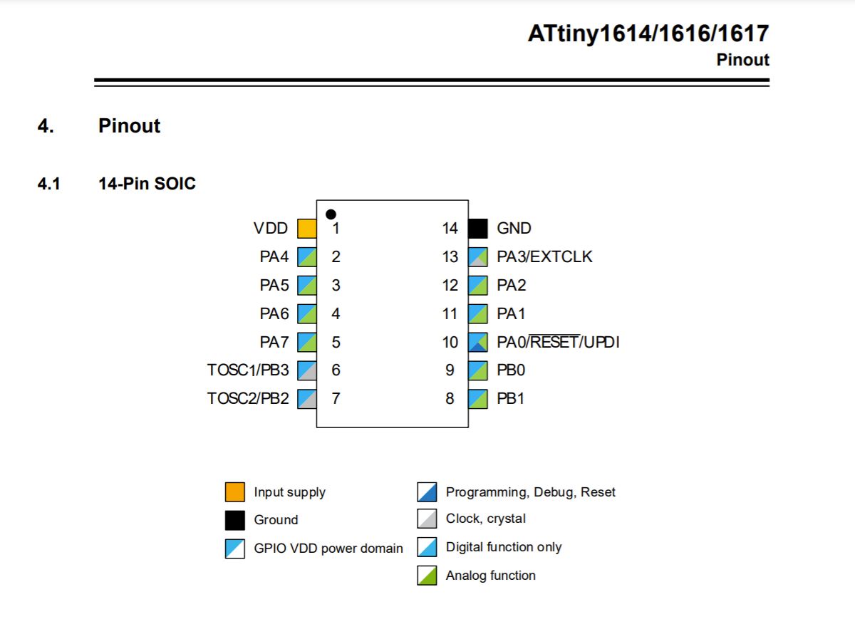
I used a ATtiny1614 microcontroller to enable the different pieces to talk to each other. The UPDI and FTDI would interact with the computer, where the chip would be powered using the 5V via the USB, would send and receive signal via Tx and Rx, would read the capacitive sensing to control the motor and peltier chips.
AttinyPinout
USE OF CAPACITIVE SENSING
The objective was that the presence of a hand should trigger the circuit.
What processes were used?
So the logic is that the capacitive sensors second capacitor plate is the human hand. I put a resistor of 1MOhm such that the capacitor takes a longer time to charge. Once it charges, the presence of the hand will finish capacitor circuit and decrease current flowing through that part of the circuit and hence reduce the values of current flowing. The physical hardware is pretty straightforward for this part.
Put a large metal plate across a resistor and connect it to two pins on the tiny.

Schematic:

the circuit for capacitive sensing

The next step after this was to write and program the attiny1614 with the code for Capacitive sensing. To do this, I read up about capacitive sensing on arduino library.
Link: Arduino for Capacitive Sensing
I learned a lot about coding trying to use the arduino library for capacitive sensing. I couldn't find one for attiny 1614, so used the ones I found but it would simply not interact with my physical hardware.
This took a few days of troubleshooting, as anything in the circuit could have been the culprit - the tiny not working, there being a shorting issue with the tiny pins and so on. I even tried code used by my colleague Alejandro Diaz for his capacitive sensing journey with the tiny. You can find it here - Link: Alejandro's Capacitive Sensing Page!. To no avail!
For me to move forward, I would have to first resolve the issue of the tiny not interacting with the computer. We identified two issues:
1. Library imcompatibility: I had to involve the teaching staff in this journey after I failed at programming the code. Anthony fiddled around with the arduino capsense library and it was to my great relief that he too, realized that the arduino capacitive sensing library isn't compatible with the tinys. 3 days spent, but finally, there was a headway. He helped me tweak the code to work for our purposes. Ok, the next step in the capacitive sensing journey was to use a new code.
2.Windows incompatibility Turns out one of the culprits was Windows incompatibility with the entire setup. I had bought a brand new computer at the start of this course, my new computer gave me interesting problems and challenges, it wouldn't read the board, no matter what I tried. The ports would just ont get recognized by the device manager or arduino ports or couldn't even be found on git bash. So i had to go on a wild goose chase to get the usb-c to usb 2.0 hub.
Finally, I resolved this issue by installing a new port library.
.png)
Then, I attempted to write my own code based on what I had learned about what needs to happen from all the experimentaiton with coding for capacitive sensing so far. I had to assign two pins values. In the The whole point it that the capacitive sensing plate will slowly gain and lose voltage between o and the maximum. The whole point is to get readings somewhere in the middle of those ranges. So, assign one pin a high, the other pin a low at specific intervals and get readings in the middle of those cycles. This is the code I was working with:
Based on this understanding, here's the code I wrote:

Did this code work? Yes!
Here's a video:
Part 2: Simulating Body Pressure
For my Project, I want to be able to use capacitive sensing as a trigger to inflate and deflate a blood pressure cuff.
Once this happens, we can hopefully feel the hand grabbing on to us, which is supposed to trigger the emotion of someone missing you. And in todays day and age, i believe being reminded that someone’s missing you is very important.
My blood pressure cuff's air is controlled by a peristaltic pump which circulates the air inside of the cuff. You must have seen a blood pressure cuff in action. A ball-shaped pump handheld, is squeezed to pump air inside. I am replacing the ball-shaped pump with a peristaltic motor. The idea is that when the motor runs in one direction, it will fill air in, when in the other direction, it will throw air out and hence when the cuff is around your hand, you will feel the grip tightening on you. In an ideal case scenario, your loved one will be touching a screen (capacitive sensing) in one part of the world and you, here, will be taken by surpris when the cuff starts to tighten around your arm and that's the indication that they are missing you.
The peristaltic pump is securely latched onto the motor. Its two pipes are connected to the two pipes of the bloodpresssure cuff.

For my output week, I am keen on having the servo motor be triggered with code and eventually I want to be able to manipulate it's speed etc.
Motor Clockwise, Anticlockwise Program
The first thing I did was write a program that can control the motor to run clockwise and anticlockwise.
 The important thing to note is calling pin names in Arduino is not exactly calling the pin number. We have to refer to this schematic again:
datasheet schematic>
 My motor one leg is connected to Pin 12 on the chip, which can be called using its port name PA2 (which can be a bit complicated to call) or by the brown/blue numbers, in this case 9.
Similarly, the other leg is connected to Pin 11 on the chip, which can be called using its port name PA1, so I call it using 8 in Arduino. Here is my code:
My motor one leg is connected to Pin 12 on the chip, which can be called using its port name PA2 (which can be a bit complicated to call) or by the brown/blue numbers, in this case 9.
Similarly, the other leg is connected to Pin 11 on the chip, which can be called using its port name PA1, so I call it using 8 in Arduino. Here is my code:
After writing this, I compile the code by clicking the verify (checkmark) button in the Arduino IDE. I then copy the .hex file from my Hexes folder into the folder containing the sketch. Then I go into CMD and cd into the Arduino folder containing the sketch and input:
python3 C:\Users\jkrit\Downloads\pyupdi-master\pyupdi-master\updi\pyupdi.py -d tiny1614 -c /COM9 -b 115200 -f motor_2.ino.hex -v
Here is the result:
However, i didn’t get it right in the first 20-30 tries. Every time I would plug in the board to try and run the code, my board would fry and i would smell solder and see smoke. Trying to understand the issues, I had to debug everything, starting from the Attiny.
This wild goose chase finally got me to a point where i realized that mosfet which was supposed to control the peltier chips, which would heat up the cuff was the culprit. The way the mosfet was drawn on my board, it wasdrawing current directly from VCC, while it should’ve drawn current from VDD.
Refer to the following schematic.

Here's the final crop:
 So, i made some addendums to the circuit, i cut the trace here, and reconnected it here.
This dind’t help however, the board was still getting fried.
For now, what i knew was this - that the moset was frying the circuit everytime i connected it. This led me to solder and resolder through 15 tinys over the course of 4 days.
So, i made some addendums to the circuit, i cut the trace here, and reconnected it here.
This dind’t help however, the board was still getting fried.
For now, what i knew was this - that the moset was frying the circuit everytime i connected it. This led me to solder and resolder through 15 tinys over the course of 4 days.
 Then one time it all worked, i could control the motor through capacitive sensing.
I decided to replug the peltier to see if i could get it all to work in sync, since i had added a diode this time, so thought i was gpong to meet with success. Worst mistake ever. The tiny fried yet again. And by this time, id used it over so many times, that the traces got discoloured.
Then one time it all worked, i could control the motor through capacitive sensing.
I decided to replug the peltier to see if i could get it all to work in sync, since i had added a diode this time, so thought i was gpong to meet with success. Worst mistake ever. The tiny fried yet again. And by this time, id used it over so many times, that the traces got discoloured.
I had done all I could but I couldn't find a way to incorporate the peltier so I decided to remove that from this system altogether.


Then, I cut new traces and resoldered everything again, minus the peltier system. I wrote code combining the capacitive sensing and the motor rotation.
Here's it:


Now, the thing to do is to connect all different systems.
Here's the circuit with all parts:
.png)
Now, the final video working would be shown in three parts. It was broken down in three parts because it's difficult to upload and manage one long vidoe.
part 1: Here's an explanatoary video of the capacitive sensing working:
Next, Here's a video of the capacitive sensing triggerhing the motor.
three, Here's the video where the motor actually managed to fill the bladded with air! (Vimeo is doing something funny, scroll to the end!)
Reflection
CHALLENGES
Pressure: Adjusting the pressure using a power source became a tricky issue.
Temperature: I tried to use the electricity to heat up the pad, which didn't work.
Pulse: Rapid change in electric field or vibrations: It was hard to control the readings of the capacitive sensing initially and I was getting outputs that made no sense.
Real time: Live data being fed into the system - although we got to work it this time, I wonder how it would be when we are ready to make this into a commericla product. It would've to be thoguht through for consistency in readings.
REFLECTIONS
This poject is a culmination of multuple short assignments where we were showed how to work with electronics, debug and code.
Electronics: I don't think making my own microcontroller is such a good idea. It is great for soft robotics but only if it is done well. But given the amazing amount of sensors and boards created by companies like Adafruit, it makes more sense to use what is there so I can focus on prototyping the concept.