final project: final electronics design
November 15, 2020
final pcb
Now that I knew how the solenoid and stepper motors worked after a week of debugging and experimentation, I was ready to start designing my board for my final project. The components I planned on using were the solenoid (1 pin), speaker (1 pin), and stepper motor (4 pins). Luckily the ESP32 CAM had 7 pins available for use, so it looked like I would have just enough pins to use one board for all features. With this in mind, I started to use Eagle to design my PCB. One annoying problem I ran into was that there was no ESP32CAM Eagle symbol for me to use, so I had to find the female surface mount connectors with offset legs online. The only one I could find was for 20 pins when I only needed 8 pins, so I edited the downloaded Eagle library so the header would only have 8 pins. I then had to space two of them 22.85mm apart (as seen in the ESP32CAM datasheet) to emulate where my ESP32CAM would go. After this, I had to ensure the use of the switch to put the ESP32CAM into program or run mode and the rest was relatively straightforward as I followed the design I used when I was experimenting with the solenoid, stepper, and speaker.
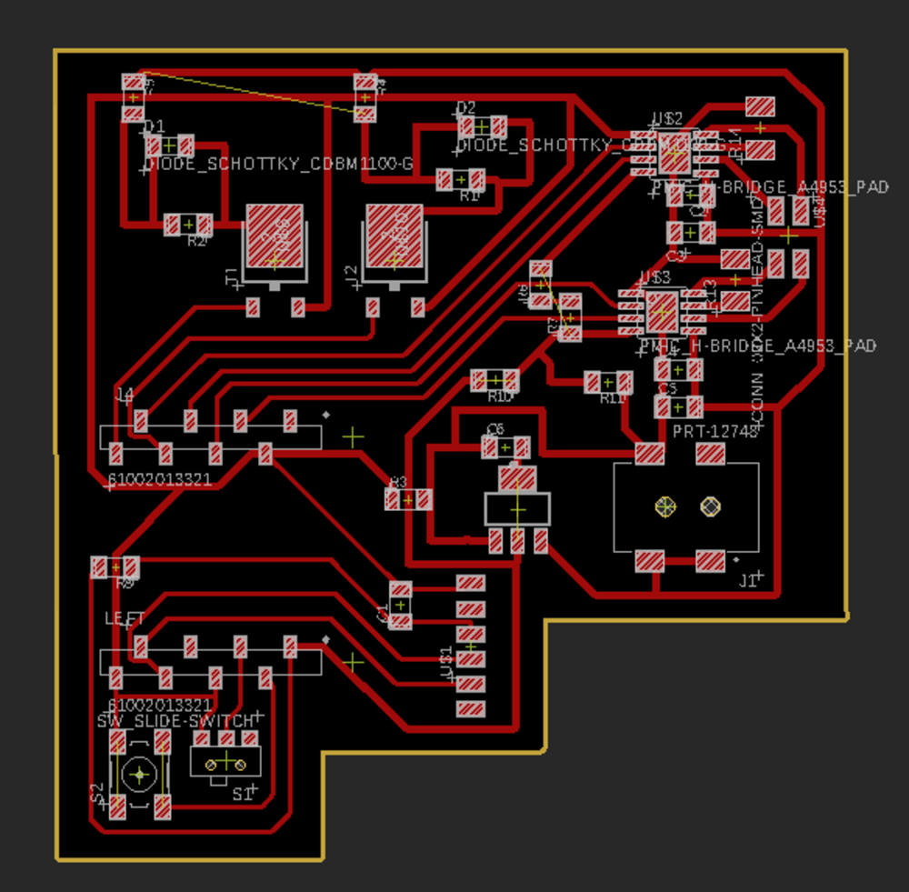
Final project board
On the bottom right of my board, I plan to put a barrel jack for a wall mount that will provide 9V of power to my PCB. I tossed on a voltage regulator to drop it down to 3.3V to safely send the correct voltage to the ESP32CAM.
Anthony was able to figure out a solution to the stepper motor problem. He found that the coil resistance of the stepper is low enough that the H-bridge detects the coil as a short and doesn't apply power. The way to solve this problem is to introduce a couple more resistors that would go into VREF of the H-bridge. Doing so would inefficiently make the stepper motor work. So I added a 5 ohm resistor and a 2.8 ohm resistor in series before passing in the power to VREF of the H-bridges I was using.
Once my board was verified, I used the Othermill to mill my board.
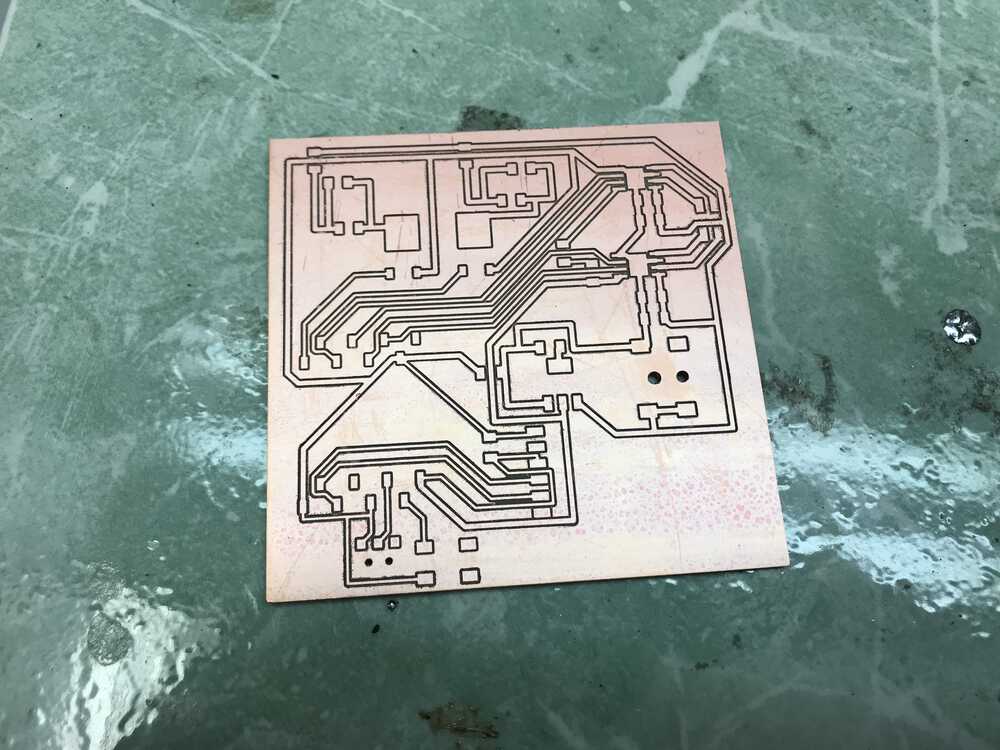
Traces of my final board
As we can see many of my traces were very close to each other, increasing the probability of solder jumping and causing a short. When I started to solder my board, it shorted and it was extremely hard to find the reason. Therefore I went back and re-cut my board and increase the clearances to .5”. This helped solve the issue of solder jumping and I was able to solder my board much easier
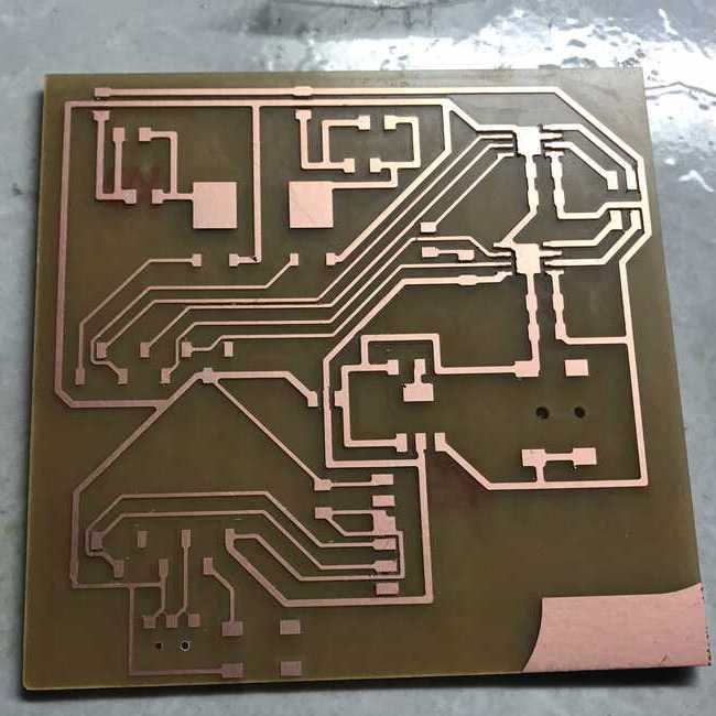
New traces with larger clearances

Soldered final board
extra: stepper housing
My disk with inserts will be in the middle of my device, therefore I needed a way to hold the stepper motor in place. I planned on using a simple stand with 4 legs to hold the stepper motor above the solenoid housing. This is important because the tube that will guide the treat to the solenoid must be close. After measuring the stepper motor, I was able to CAD the housing for my stepper motor.
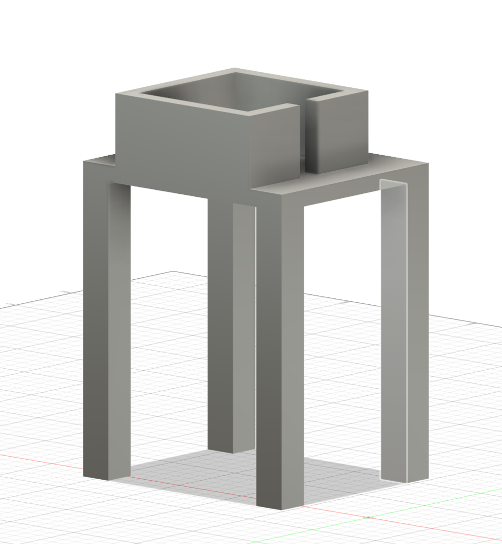
CAD for stepper housing
I printed out the section where the stepper motor would sit on the Sindoh to experiment with the fit. I also included a cut out for where the wires could stick out.
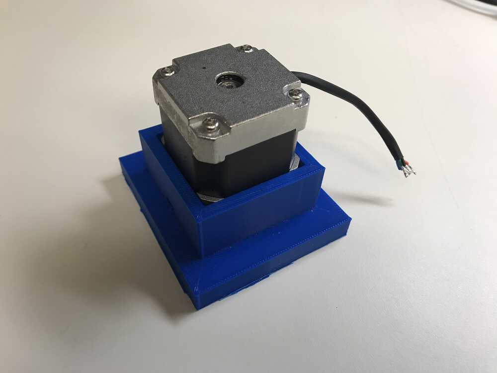
Stepper motor holder experiment
I didn’t center the stepper motor due to the tube that is sticking out of the disk base. This tube base should be positioned right over the solenoid launcher.
Additionally, as noted before, I was planning on making the solenoid holder part of the device housing. I was also considering having the stepper motor housing also be part of the device housing. However, this would make it hard to access the solenoid launcher and debug any issues. So I planned on having the stepper motor housing be detachable by having 4 inserts in the device housing that fit snuggly with the 4 legs of the stepper motor housing. This now allows me to remove the stepper motor housing if there are any issues.
Additionally, as noted before, I was planning on making the solenoid holder part of the device housing. I was also considering having the stepper motor housing also be part of the device housing. However, this would make it hard to access the solenoid launcher and debug any issues. So I planned on having the stepper motor housing be detachable by having 4 inserts in the device housing that fit snuggly with the 4 legs of the stepper motor housing. This now allows me to remove the stepper motor housing if there are any issues.
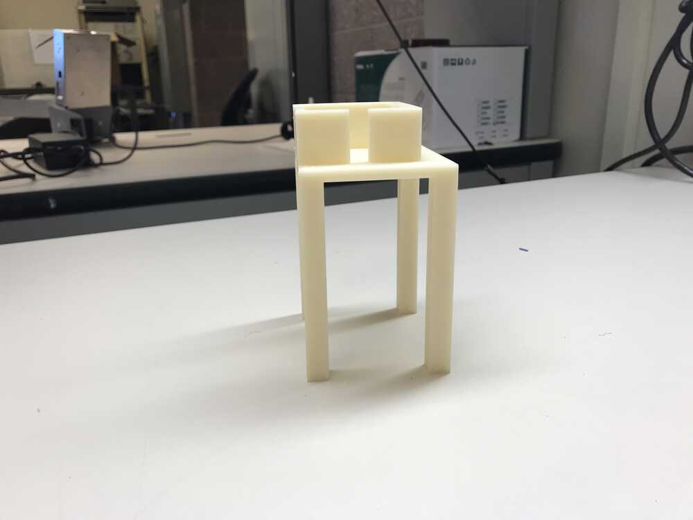
Printed final stepper holder
One thing I overlooked was that my tube from my base was pretty close to the stepper motor, and when I put the stepper motor into the housing, the wall got in the way of the tube so it wouldn’t fit. To save time and PLA, I just cut an indent to allow the stepper motor to fit and the tube to slide in place.
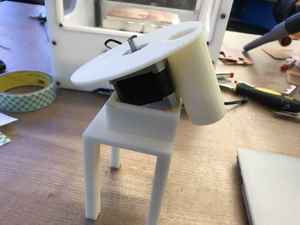
Base doesn't fit with stepper housing
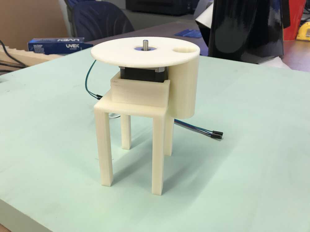
Stepper motor housing cut to fit base
extra: magnet case
To increase the surface area of my launcher, I 3D printed a cover that would go over the two magnets I would attach to the screw I was using with my solenoid. CADing the cover was straightforward as I just needed to make sure the magnets would fit tightly in the cover so it wouldn’t come off. I experimented with two sizes with one magnet case having an internal diameter of 12.85 mm and another with a diameter of 12.7 mm (both had a total diameter of 20 mm). The 12.85 mm magnet case fits perfectly and the two magnets fit into the insert.
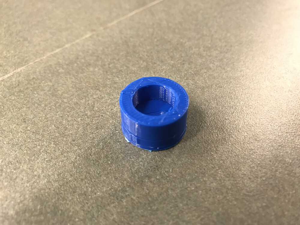
Magnet case

Magnet case with screw
NEXT>