week 5: electronics production
October 14, 2020
assignment
1. make an in-circuit programmer by milling and stuffing the PCB,
test it, then optionally try other PCB processes
setting up clank
Some of the staff has worked on creating a 3D-printed take home PCB mill and we got the pieces at the beginning of the week. I thought it was super cool to be able to create PCBs in the comfort of my dorm room. So I started to assemble the Clank-LZ Machine on Thursday. It took much longer than I expected (~8 hours) to assemble and ran into many smaller problems that prevented the machine from working. One problem was the micro USB cord I was using -- I used the cord that came with our lamp which didn’t have a data line running through it. However, once I got clank working, I was ready to start making PCBs.

All the clank pieces before assembly

Clank fully assembled
pcb production
This week I set out to make an AVR USB circuit board. I first started my journey by meeting with Anthony and learning about the PCB mill they had at the EECS shop and tips on how to solder (I have very little experience with soldering). After getting a better idea on the entire process of creating PCBs, I set out to mill my own board with my clank machine.
Before I started, I grabbed the png files for the traces and interior from the HTMAA website. I then passed these png files through mods, the software made by Professor Gershenfeld. Mods converted the png file to gcode specific to the endmill that I was going to use. I used the 1/64” end mill to cut the traces and uploaded the gcode. For each mill, we need to calibrate the z value by manually moving the end mill to the point where it touches the bed. Once this was done, I started to cut my PCB and it turned out very nicely. It took around 10 minutes to complete.
Before I started, I grabbed the png files for the traces and interior from the HTMAA website. I then passed these png files through mods, the software made by Professor Gershenfeld. Mods converted the png file to gcode specific to the endmill that I was going to use. I used the 1/64” end mill to cut the traces and uploaded the gcode. For each mill, we need to calibrate the z value by manually moving the end mill to the point where it touches the bed. Once this was done, I started to cut my PCB and it turned out very nicely. It took around 10 minutes to complete.
Clank in Action
I then swapped the current end mill to the 1/32” end mill. I recalibrated the z value and started the job. Unfortunately, I believe the z value was not properly calibrated, since the 1/32” end mill went too deep and got stuck in the bed. As the top plate tried moving along the x axis, it snapped the end mill. This was extremely sad, and I wasn’t able to go into the shop to get a new end mill since it was too late.
I was able to get a new end mill over the weekend and figured that the biggest mistake that I made was not flattening the bed. This is critical because there is no guarantee that the machine’s bed will be flat with respect to the machine’s own geometry. I think this is the reason I snapped my first end mill.
I ran into more problems, as my end mills didn’t completely fit in my shaft adapter. This was problematic because the end mills would not stay in place, no matter how hard I pushed the end mill into the adapter. Anthony helped me out on Monday and pried the shaft adapter open enough to fit my end mills.
Now with everything (hopefully) set, I was able to flatten the bed. I zeroed all axes to the bottom left of the bed and started to flatten. I was left with a small square indent where the bed was flattened.
attempt 2
I now started to cut out the traces. Based on others experimenting, I found that the V bit for engraving actually worked very nicely as the 1/64” end mill, so I decided to give it a try.
It did not look good. I believe the shaft adapter isn’t holding the endmills snug enough, so they are moving when rotating. I’m waiting to get a new shaft adapter to see if this solves it.
It did not look good. I believe the shaft adapter isn’t holding the endmills snug enough, so they are moving when rotating. I’m waiting to get a new shaft adapter to see if this solves it.

Bad cuts by the clank
attempt 3
After receiving the new shaft adapter, I was able to fit the endmill snuggly into the adapter which solved the issue with my end mills rotating the shaft adapter while milling. The arm of my clank had too much movement in the x-direction, so I took a look at the left and right pieces. It turns out that the pulley disconnected from one of my motors contributing to the poor cuts. I quickly fixed those changes and started cutting. I also used different mods settings given by a suggestion by Anthony: (changed cut speed and plunge speed 1.7).
>
With the V bit, the cut looked really nice. I was also then able to cut the interior of my PCB. It looked so much better than the previous cuts. One mistake I made was re-calibrating the origin with the new end mill. When I did so, it offset a little to the left which led to the traces not being centered on the cutout.

Good traces cut by clank

Decent outline cut
I then decided to experiment with the 1/64” bit so I cut out the hello.serial-UPDI PCB that was on the HTMAA website. The traces turned out nice.
>
>
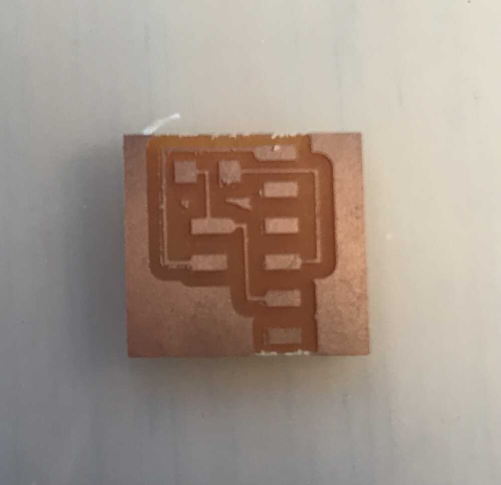
Good traces cut with 1/64" end mill
I then was able to solder my PCB which was great practice and here is my final PCB.
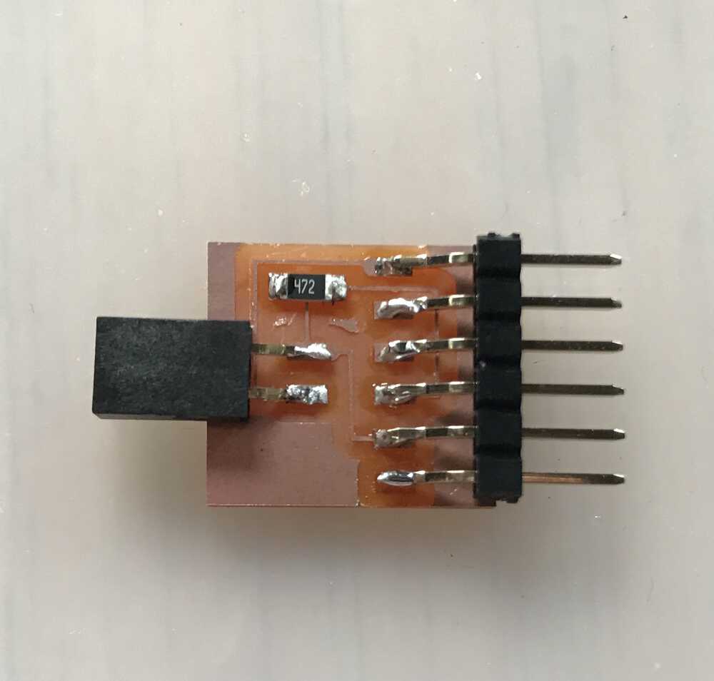
Final PCB after soldering
NEXT>