
This week's assignment is design, build, and connect wired or wireless node(s) with network or bus addresses.
This website here is a great resource for the pinouts diagram and knowing more about the pins of the ESP32 microcontroller: https://randomnerdtutorials.com/esp32-pinout-reference-gpios/

Pins I can't use: GPIO 6-11
This week my laptop keyboard was broken so I had to hand over my laptop to apple... since I was using a loaner laptop this week, I had difficulties using Fusion 360 and designing boards, so I decided just to use Neil's example ESP32 board for now:
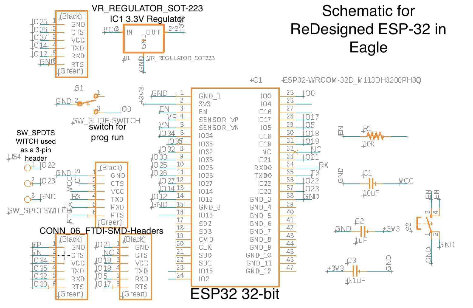
To design my on board, I used the following components in Eagle, to start with:
ESP32-WROOM-32 D0WDQ6 32 bit (I found a library file for this ESP32 microcontroller online at Components Search Engine, ESP32-WROOM-32 D0WDQ6)
https://componentsearchengine.com/part-view/ESP32-WROOM-32D(M113DH3200PH3Q0)/Espressif%20Systems
In Fab library, I found the components for prog and for the regulator:
SW_SLIDE-SWITCH for prog run component
VR_REGULATOR_SOT-223 for IC1 3.3V component
https://componentsearchengine.com/part-view/ESP32-WROOM-32D(M113DH3200PH3Q0)/Espressif%20Systems


Here's the data sheet diagram for the ESP32 (ESP32-D0WDQ6 from digikey).
I also used the following Components:
R1206FAB for resistors
CAP_UNPOLARIZEDFAB for capacitors
CONN_06_FTDI-SMD-HEADER (6 pins, FTDI header) and SW_SPDTSWITCH (3 pins, can use it as a FTDI header)
SW_SWITCH_TACTILE_6MM6MM_SWITCH for the button switch for reset
And I used the following commands in the command line in Eagle:
net (to add lines on resistors)
value (type this in, then click on a resistor, then add 10k for the value)
name (to add names to the net lines on resistors)
copy (to copy-paste a capacitor, type in copy in the command line, then click on the capacitor, and click elsewhere on the white space to paste)
When making the schematic in Eagle, I connected RX to TX and TX to RX (so, I named the TX on the FTDI header as RX, and the RX on the FTDI header as TX).
I designed the ESP-32 board in Eagle, and designed it after this example ESP32 board that Neil has on his website, except I added FTDI headers to connect the pins to other output/input devices or other connections if needed.
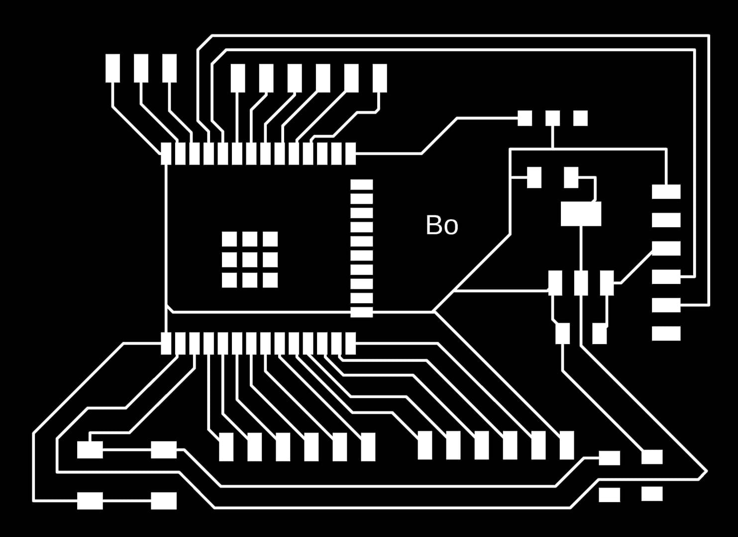
Below are the schematic and the PCB document. For more detailed instructions on how to export the PCB document to PNG (e.g. how to make the polygon and board lines and then export monochromatic), see Week 9 documentation at the end of the the page for Week 9.

Next, I exported to monochromatic Black & White PNG for use in mods to mill on the Roland SRM-20 mill:
http://mtm.cba.mit.edu/2021/2021-10_htmaa-demo/ (Here's the instructions for how to export the file PNG's in Eagle)
For the traces, I made sure each trace was far enough away from the other neighboring traces:
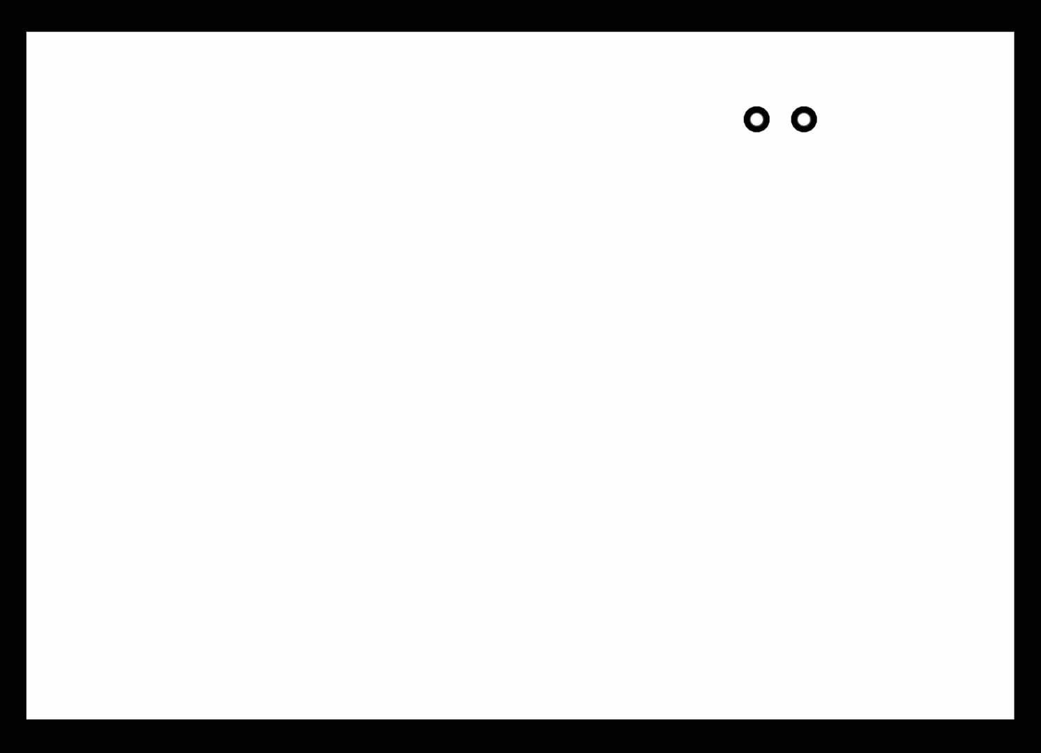
For the outline, there are two vias/dots which are not to connect to anything; they are just there to allow space for the switch which has two bumps on the back of it. Note that for the outline, to get the outside to be fully black without white dashed lines, I used Preview on Mac to create black boxes to cover up those dashed white lines around the border/perimeter of the outline below. The file below is the edited version of the outline where I removed the dashed white lines in Mac Preview App (paint app or some other app like Photoshop also would have worked fine):
Strangely, while milling with the 1/64" end mill, I noticed little strings coming off of the end mill. This hadn't happened to me before.

Next, to build the board, I worked on soldering / stuffing it.
But then I realized that the footprints were all connected to each other for the ESP32!! So, I modified them in Eagle:
1) Go to PCB Document (where you've drawn the blue polygon etc. and can see the routing)
2) Right-click on the + cross sign that's near the middle of the ESP32
3) Open Device. You should now see a schematic pop up.
4) Click Footprints in the left hand menu
5) Double click the resulting Name in the list to open the footprint
6) Now that you see the footprint, right-click on one of the little footprint pads on the board
7) In the popup right click menu, click on Properties
8) Under Smd size, select 66x32, and click OK.
9) Click on the name in the footprint menu on the left, and then File > Save As > and rename it.
10) Go back to board > Right click the component > Replace. Select your renamed file from 9).
Yay! Repeat this for every other footprint on the ESP-32.
Now, when I created my new board with the smaller footprints for ESP32 in Eagle, I was able to load the .PNG traces and .PNG outline files into MIT mods, with 2000 DPI, and check for the traces (click Mill Traces and then click Calculate, then click View) whether the tool path would now be able to go around the fine details of those tiny footprints for the ESP32. Yay!
Mods "View" diagram, before making footprints smaller in Eagle: 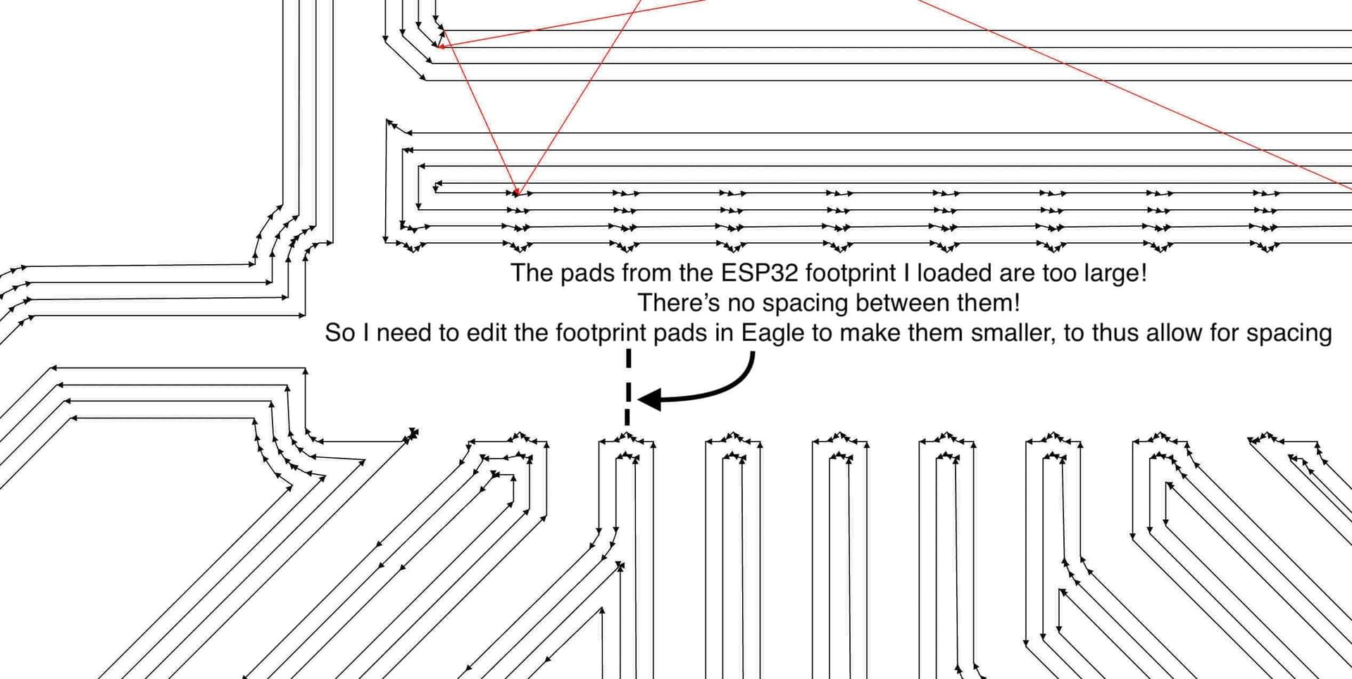
Mods "View" diagram, after making footprints smaller in Eagle:

Great! Now my board was just fine.

Next I soldered the board:

Next, I used the following code (Web server code), and used it on the archshop computer. The archshop computer was able to recognize my board in the port, while my mac laptop was not able to recognize my board in the Port.
http://academy.cba.mit.edu/classes/networking_communications/ESP32/hello.ESP32-WROOM.WebServer.ino
Note that I added this url in Board Manager preferences for ESP32 in Arduino:
https://dl.espressif.com/dl/package_esp32_index.json
I also opened the Serial Monitor, and webpage with 10.31.124.125.
I changed the wifi part of the code to:
#include <WiFi.h>
const char* ssid = "MIT";
const char* password = "";
WifiServer server(80)
Next, I did the following:
1. Turned the switch to the left side (towards the ESP32)
2. Then pressed the button on the board
3. Press the upload button in Arduino IDE software
4. Wait
5. Press the button again and turn the switch back to the left side
6. Now, you should see something show up in the serial monitor, and should see a message show up on the webpage with URL 10.31.123.125! You can modify and re-upload the code to modify the message.
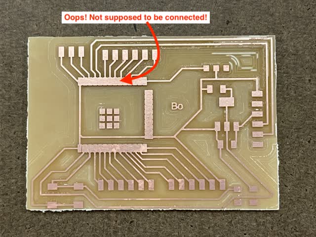
Unfortunately, I realized that I had designed my board badly, and had not fully connected the routings properly!
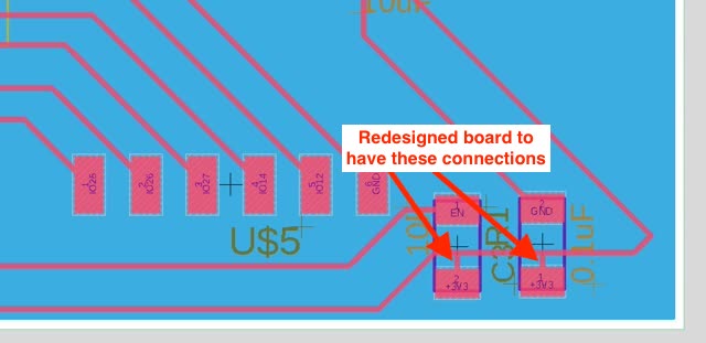
To fix my board, I used extra solder to create the connections after the fact:
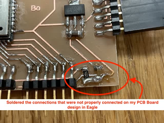
Yay!
Next, I tried again, in the EECS Shop:
Since my mac wasn't recognizing the port for my board (but windows computers were), I googled ft232rl mac driver and downloaded it, in order for my Arduino IDE on Macbook Pro to recognize the Port of the ESP32:
https://learn.sparkfun.com/tutorials/how-to-install-ftdi-drivers/all
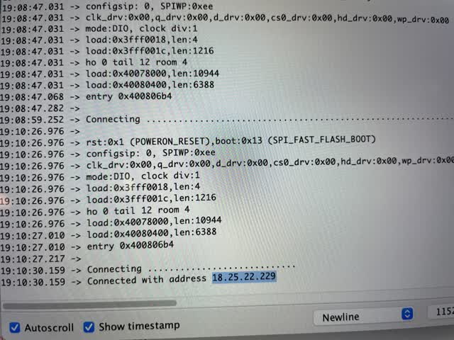
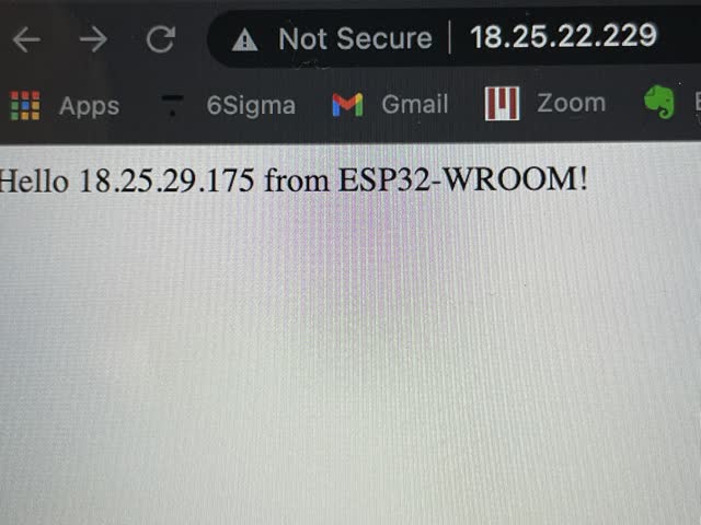
I also opened the Serial Monitor, and webpage with http://18.25.22.229/ (type in 18.25.22.229, a number specific to the computer which shows up in the serial monitor)
I changed the wifi part of the code to:
#include
const char* ssid = "EECS_Labs";
const char* password = "";
WifiServer server(80)
Next, I did the following:
1. Turned the switch to the left side (towards the ESP32)
2. Then pressed the button on the board
3. Press the upload button in Arduino IDE software
4. Wait
5. Press the button again and turn the switch back to the left side
6. Now, you should see something show up in the serial monitor, and should see a message show up on the webpage with URL 18.25.22.229! You can modify and re-upload the code to modify the message.
Here is the default message that gets sent to the server url webpage:
Here is the message that got sent, once I edited the code with my own text:
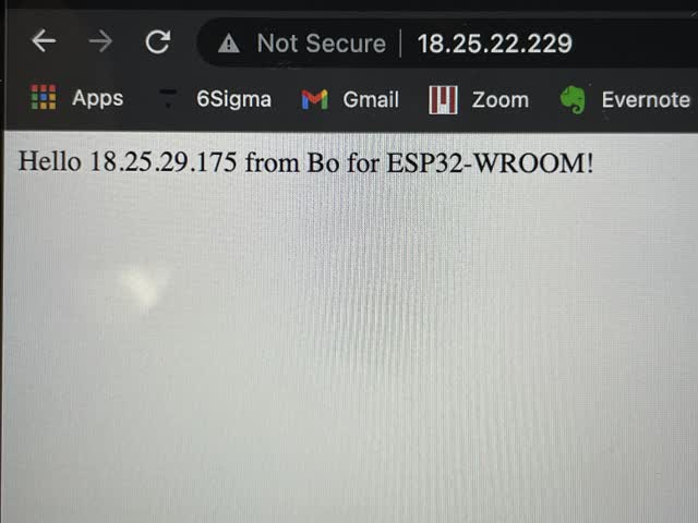
Here's how I changed the code in order to get the new custom message on the server to pop up:

The group assignment for this week is to send a message between 2 projects, for example between two ESP-32 boards, where one board controls a remote control or sensor, and the other controls a motor.
I connected the TX of my board to the RX of Emily's board, and the RX of my board to the TX of Emily's board.
Here are instructions on how to connect two ESP32's and send signals between them (code):
http://www.iotsharing.com/2017/06/how-to-use-udpip-with-arduino-esp32.html

Learnings:
Advanced Applications:
created with
Website Builder Software .