Group Assignment
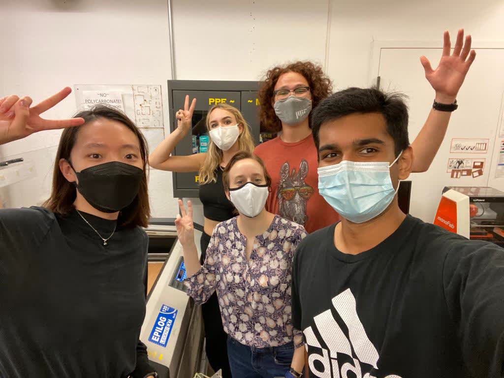
Just a bunch of well seasoned laser cutting experts!
Characterize the Laser Cutter
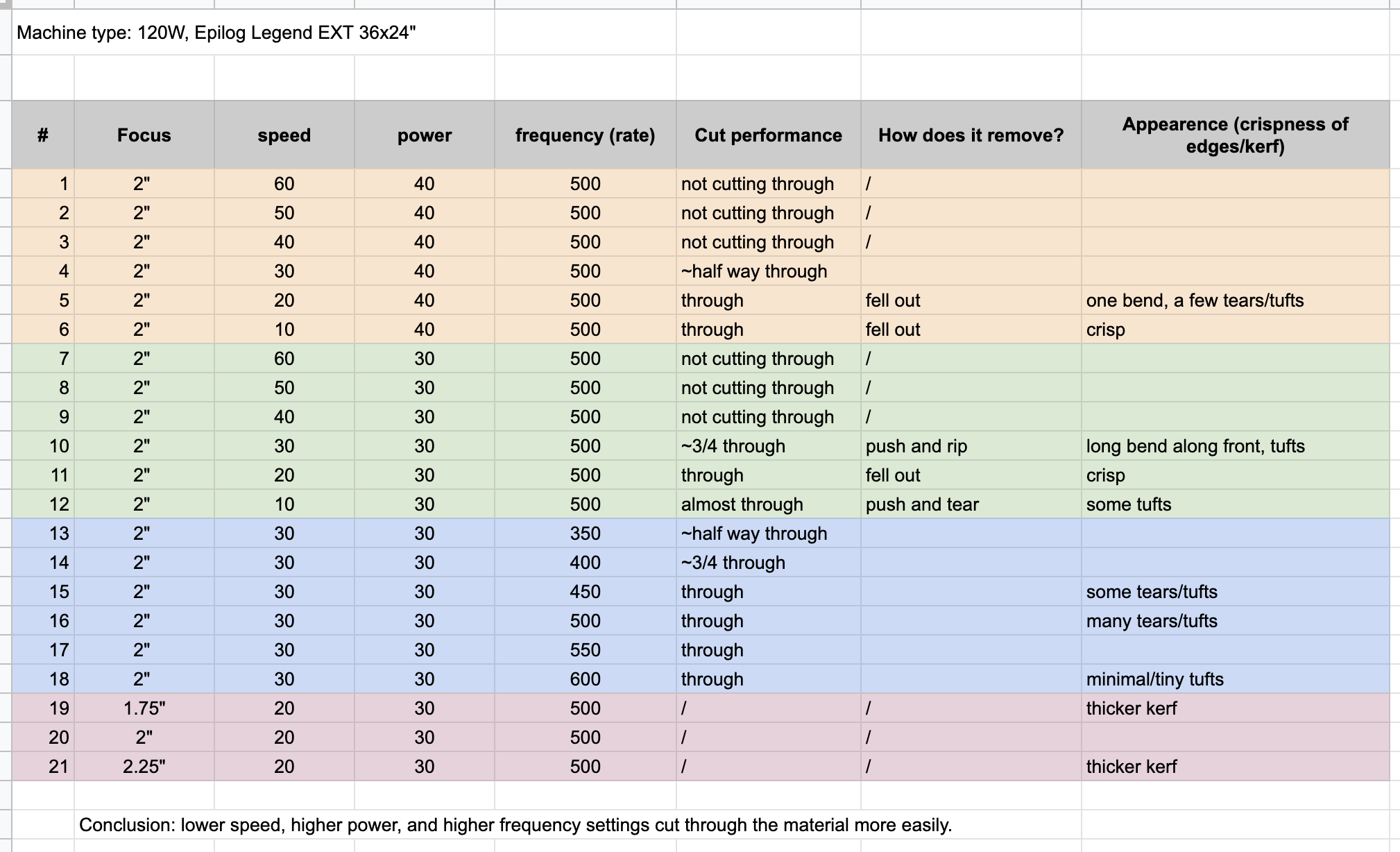
Summary of our results:
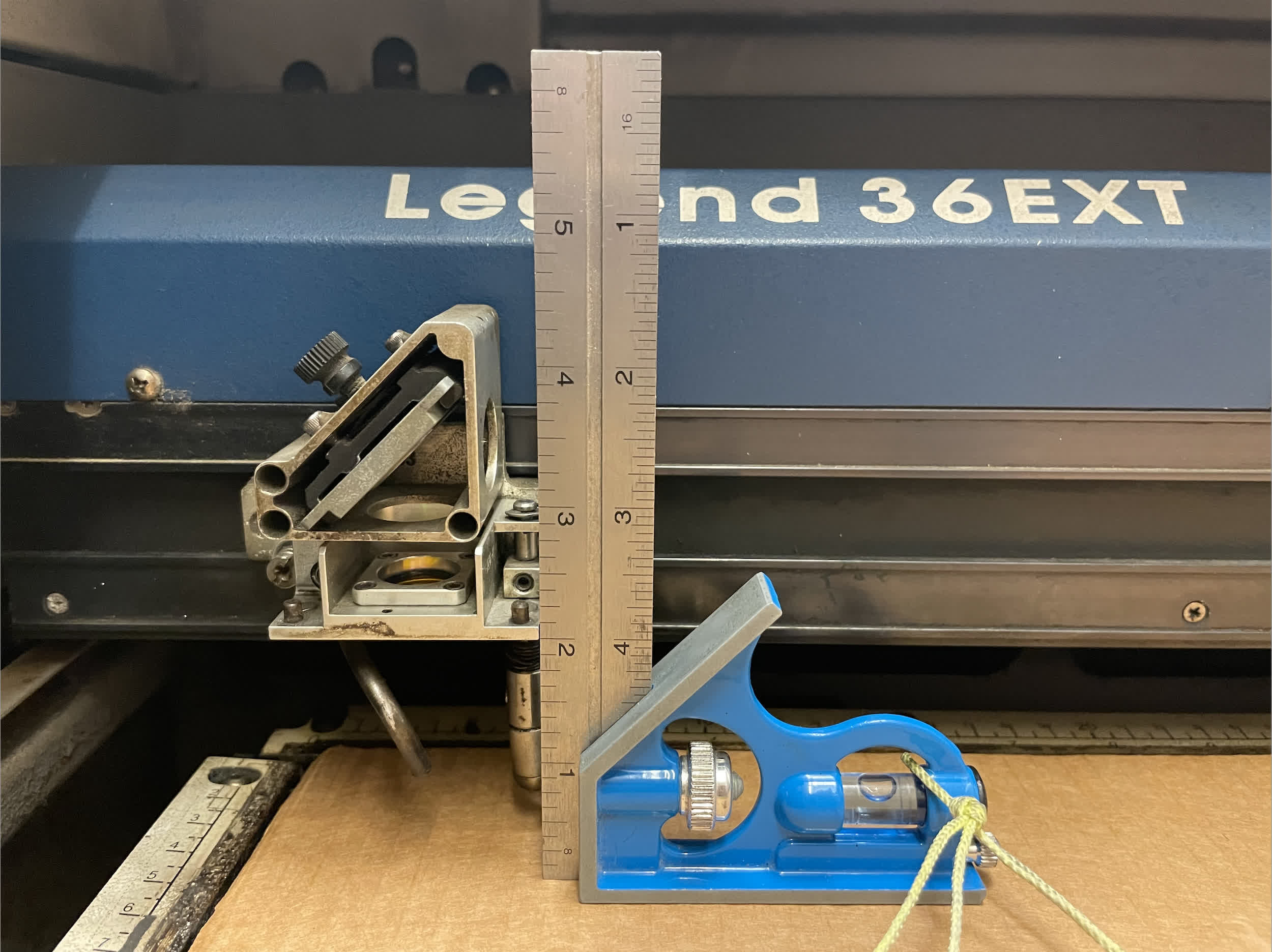
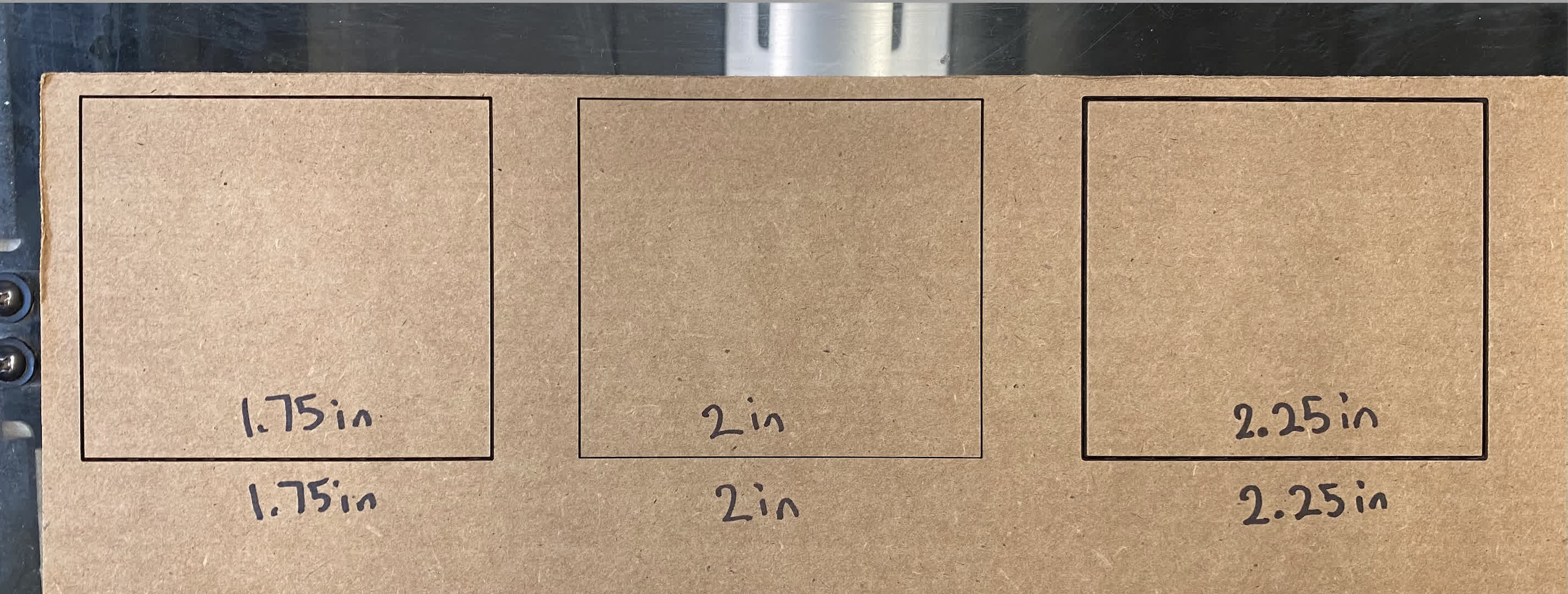
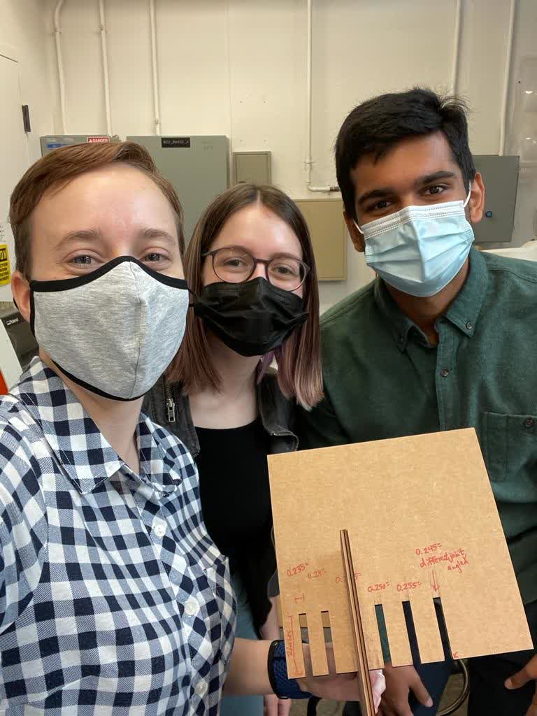
To characterize focus, we drew three squares, each with a different focus (while keeping speed and power constant). As you can see, the thickness of the cut is large, then narrows, and then increases as focus increases from 1.75in to 2.25in. This is because of the hourglass shape of the laser beam - before and after the optimal focal point, the beam width is wider, which will thus translate to a wider cut.
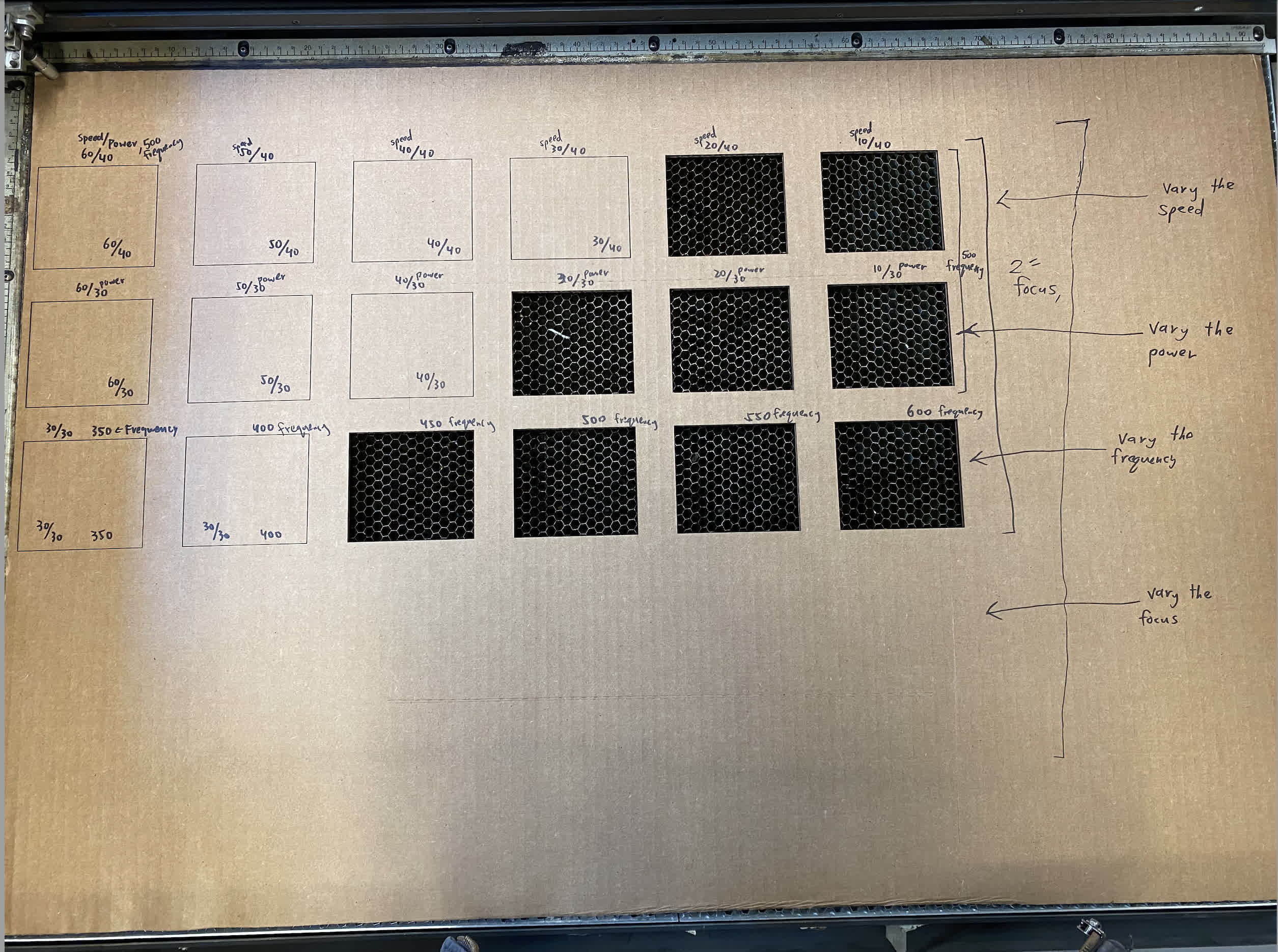
Above are all the squares we cut to measure speed and performance.
Kerf, Joint Clearence, and Join Types
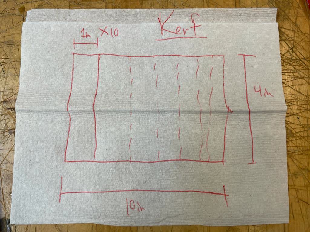
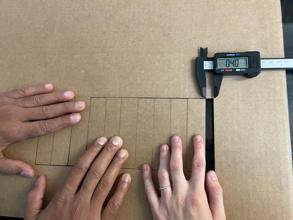
To measure kerf, our plan was to cut 10 identical rectangles right next to eachother and shift them all to one side. We would then measure how much gap was left on the other side and divide by 11. This would give us a rough approximation of our laser cutter's kerf. We had a total of 0.4in of space left, which means our laser's kerf is about 0.036in.
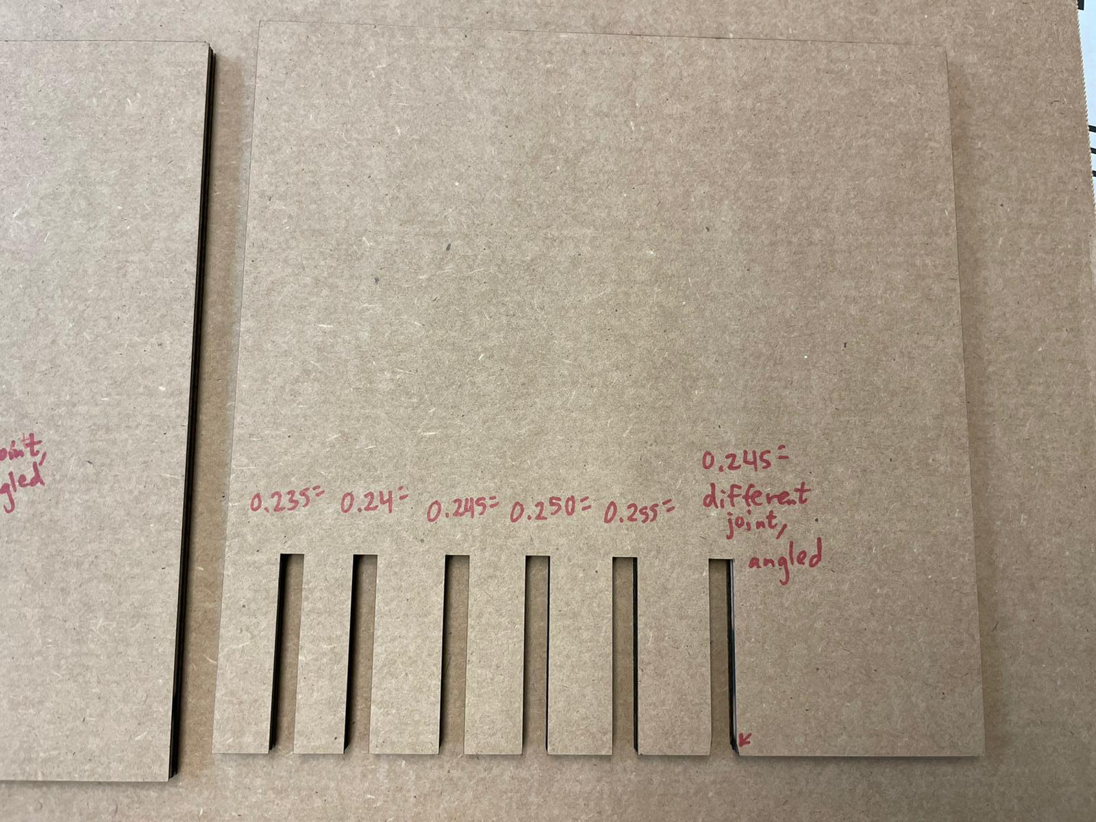
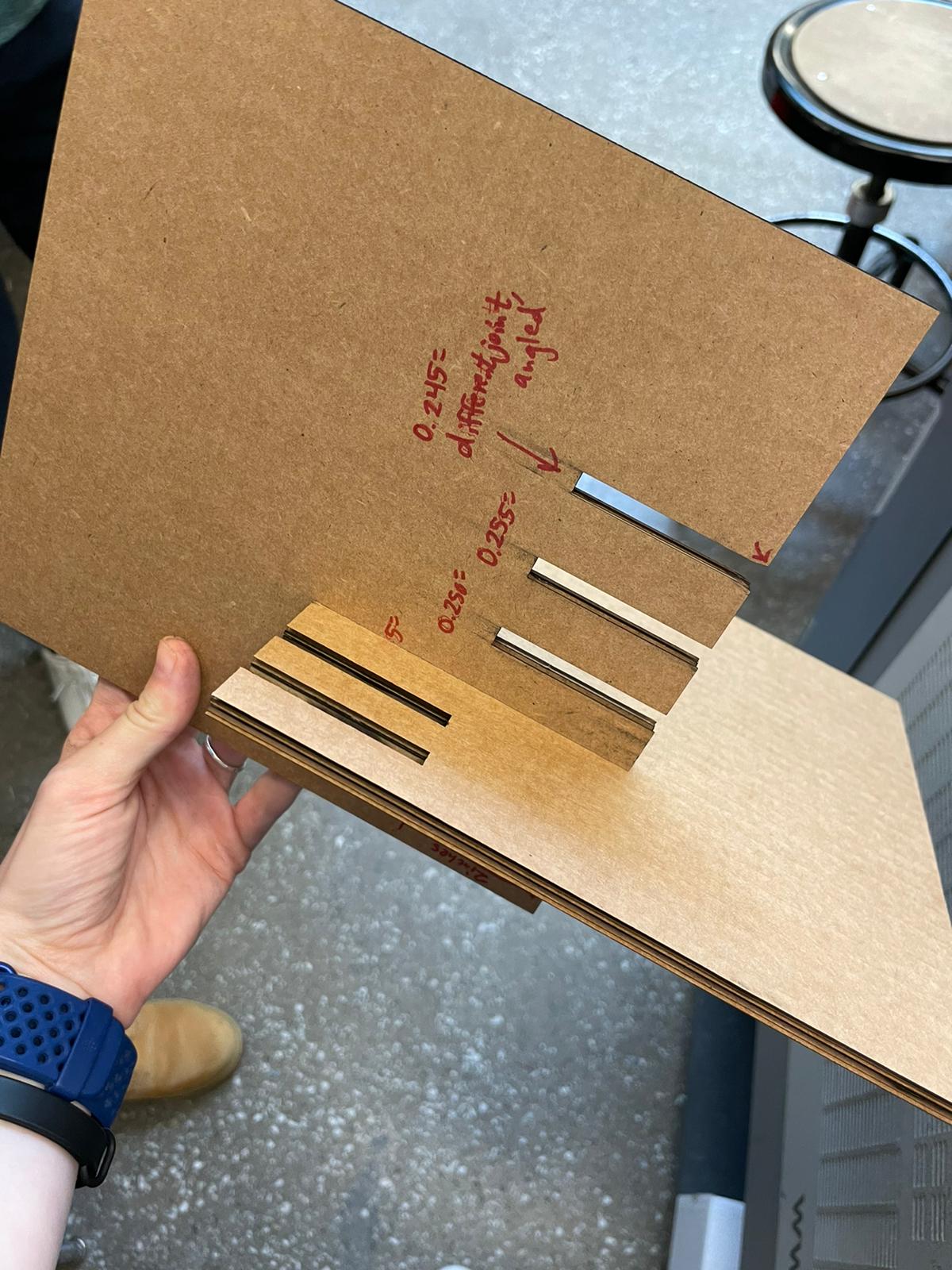
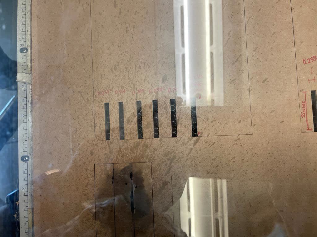
To test different joint types, we cut a bunch of joints (slits) of different widths, and we checked to see which joint had the snuggest fit. You can see this in the group photo above. We also tried a join where we cut a small diagonal on the tip to help with sliding in. We found this joint to be the best fitting.
Fire!!!
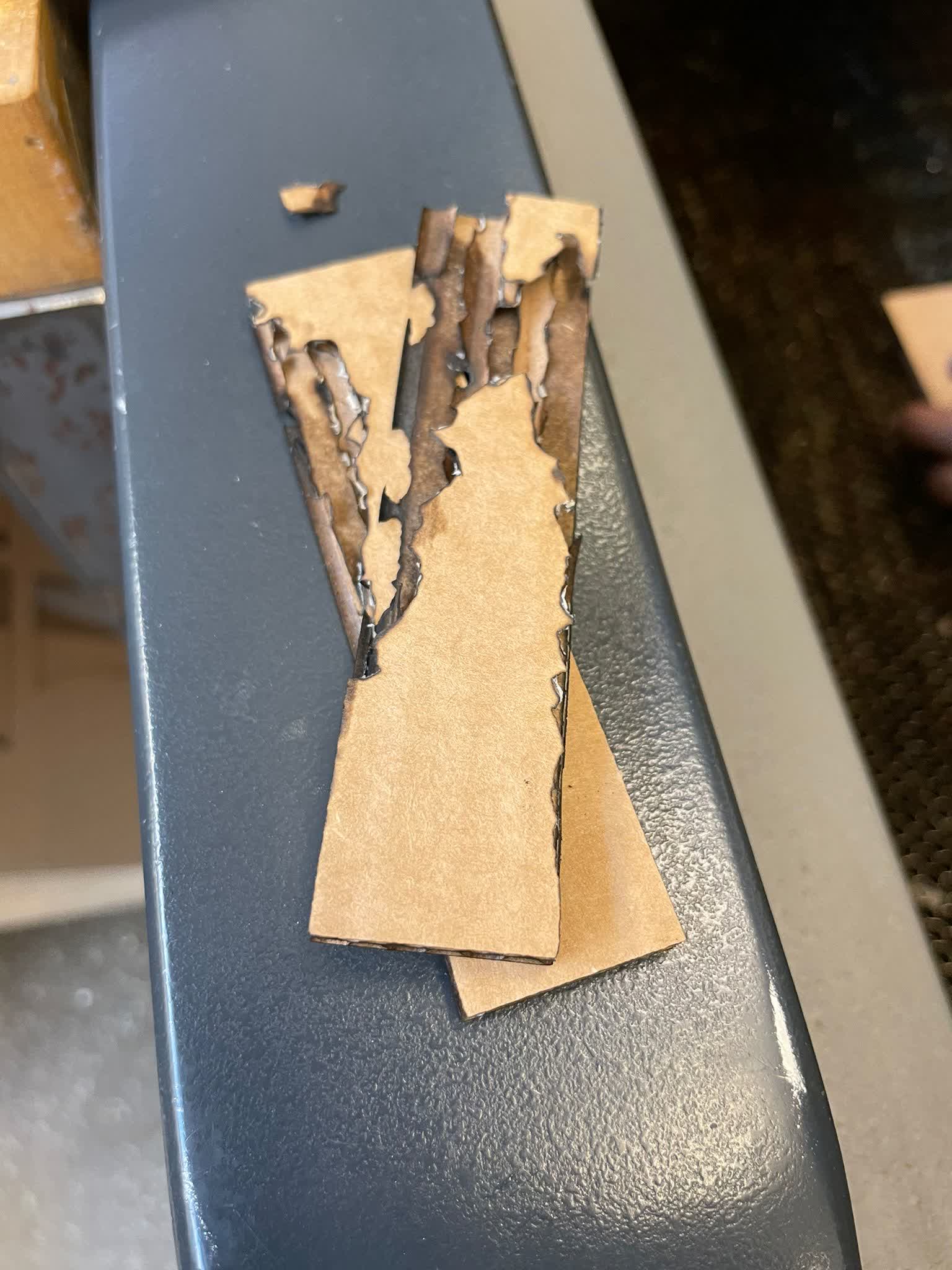
We also kinda maybe sorta started a mini fire! This happened while we were cutting out the rectangles for the kerf fit. When we saw the embers, we immediately shut the machine down and sprayed the card board. We noticed that when the machine was cutting this board, it was making two pass throughs back to back over the same line, and our hypothesis is that this caused the material to significantly heat up. We think the double pass throughs were happening because of how we set up our rectangles in Rhino (we created multiple rectanlges that were overlapping on the lines as opposed to just drawing new edges). To compensate, we just reduced the power and increased the speed so that the laser would spend less time over a particular point and be weaker.
Individual Assignment
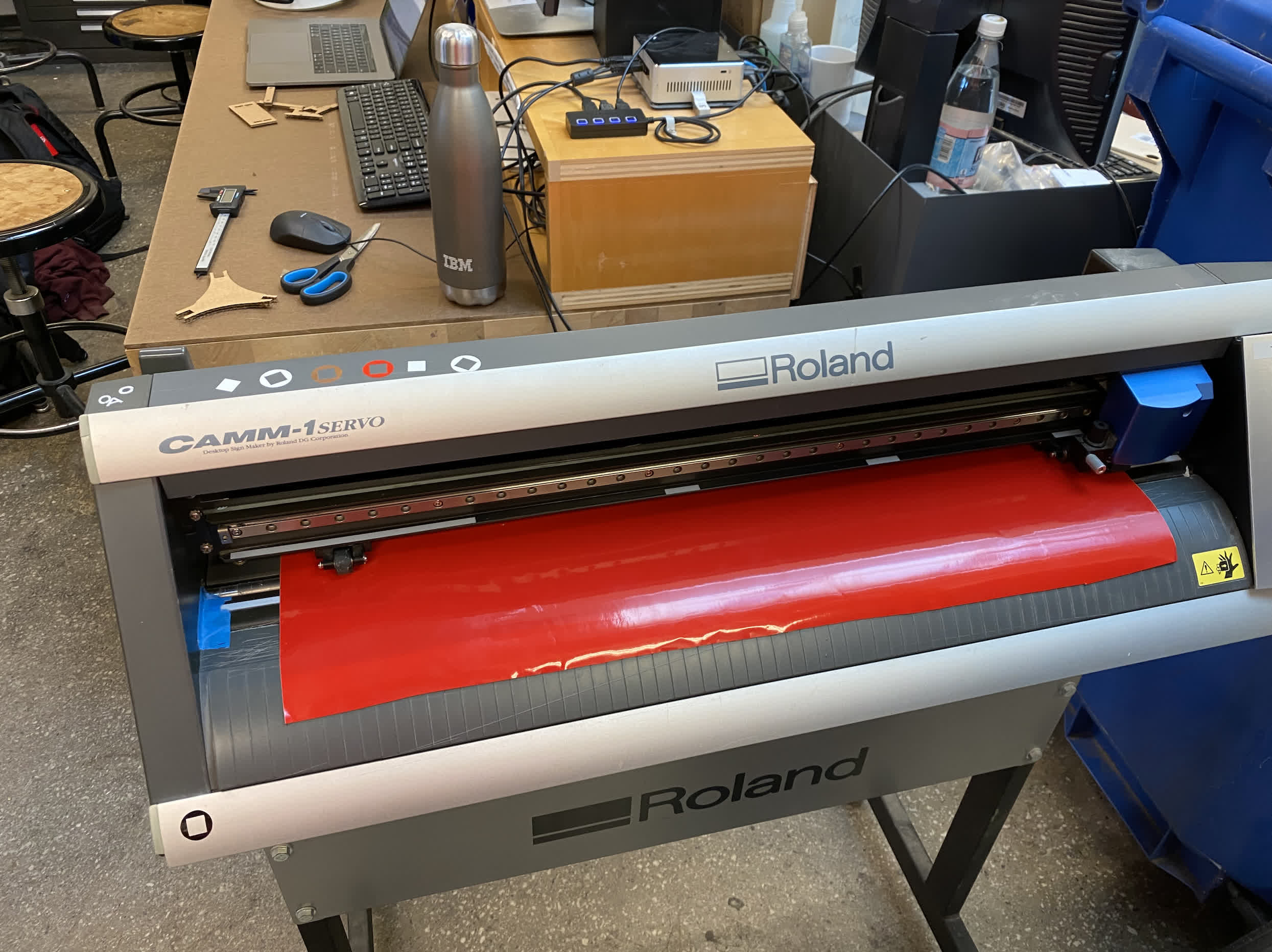
Vinyl Cutter
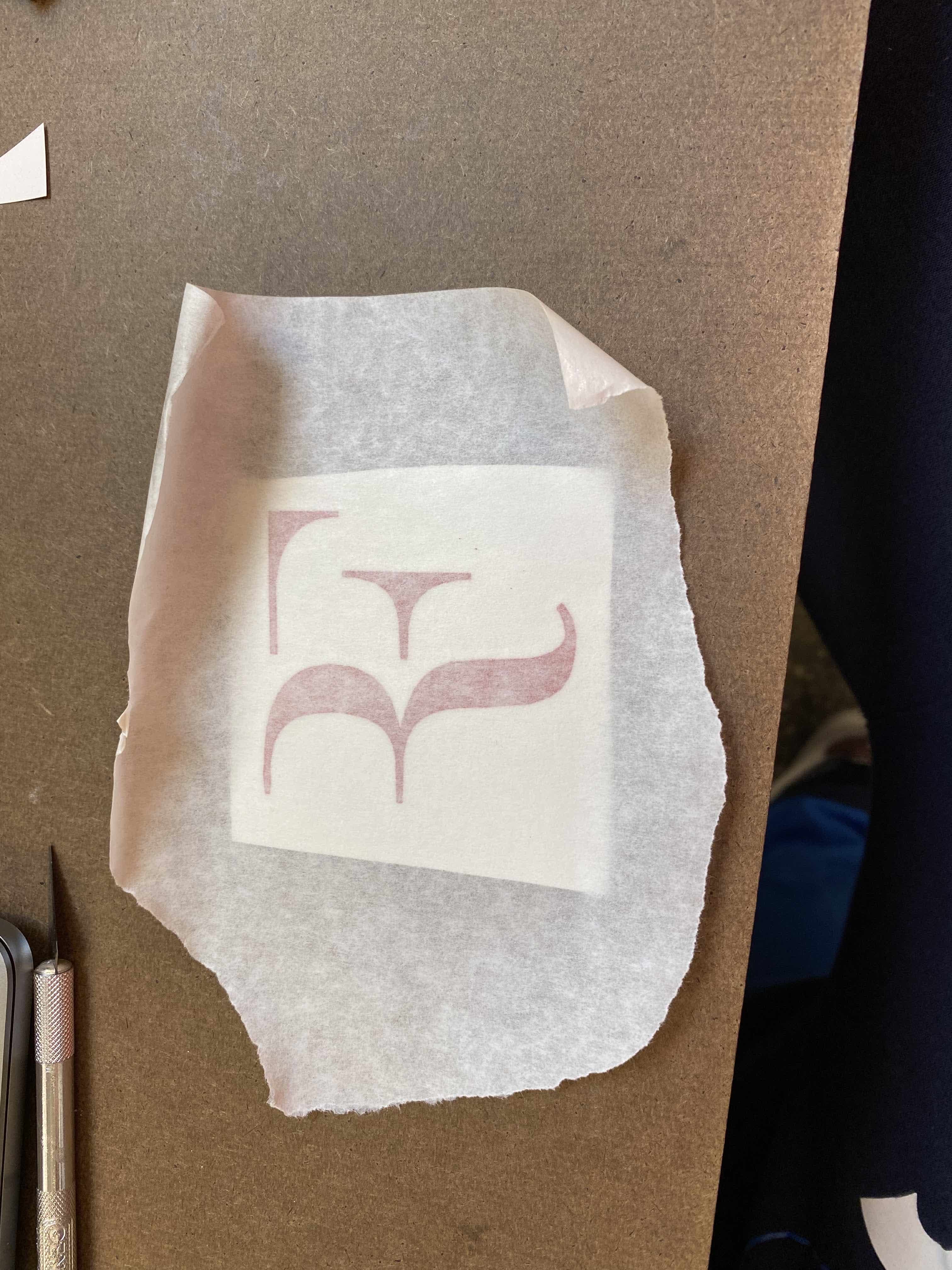
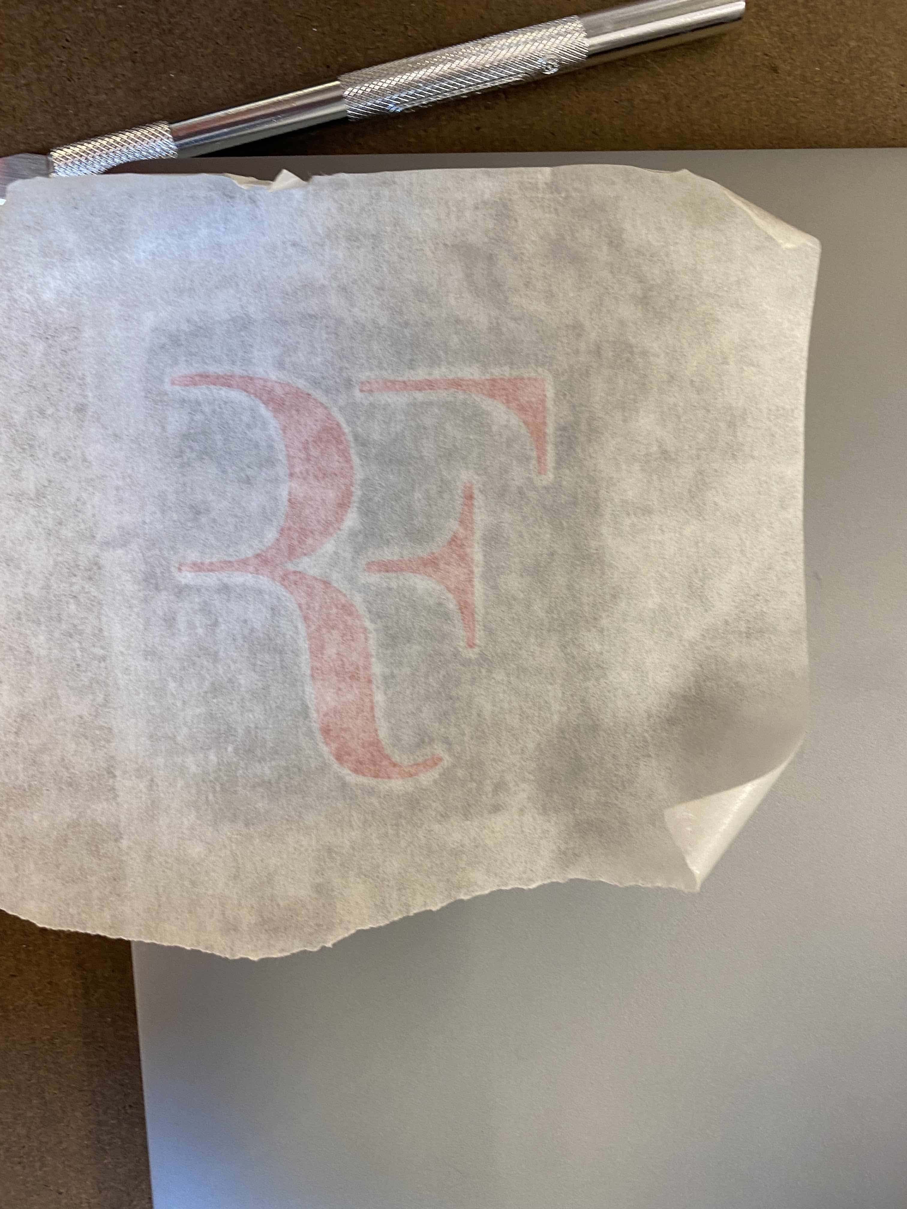
Roger Federer is my favorite tennis player, so I wanted to cut out his logo using the Roland vinyl cutter. I used the mods software on the lab machines. I initially uploaded my photo with 300dpi, but the image was too small. I then reduced to 150dpi using mods, and I was pleasently surprised to see that I did not lose noticable precision. I initially tried the recommended 90gf, but I found 100gf to perform better. Even still, it was quite difficult seperating the sticker because of the thin lines on the ends of my design. I had to use an exacto knife to hold down the edge while I peeled very carefully. Overall, I am quite pleased with the results!
Parametric Construction Kit
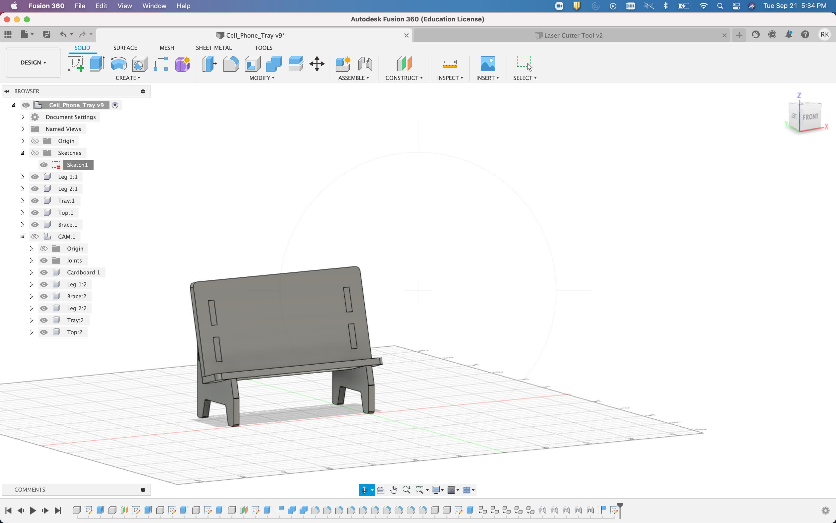
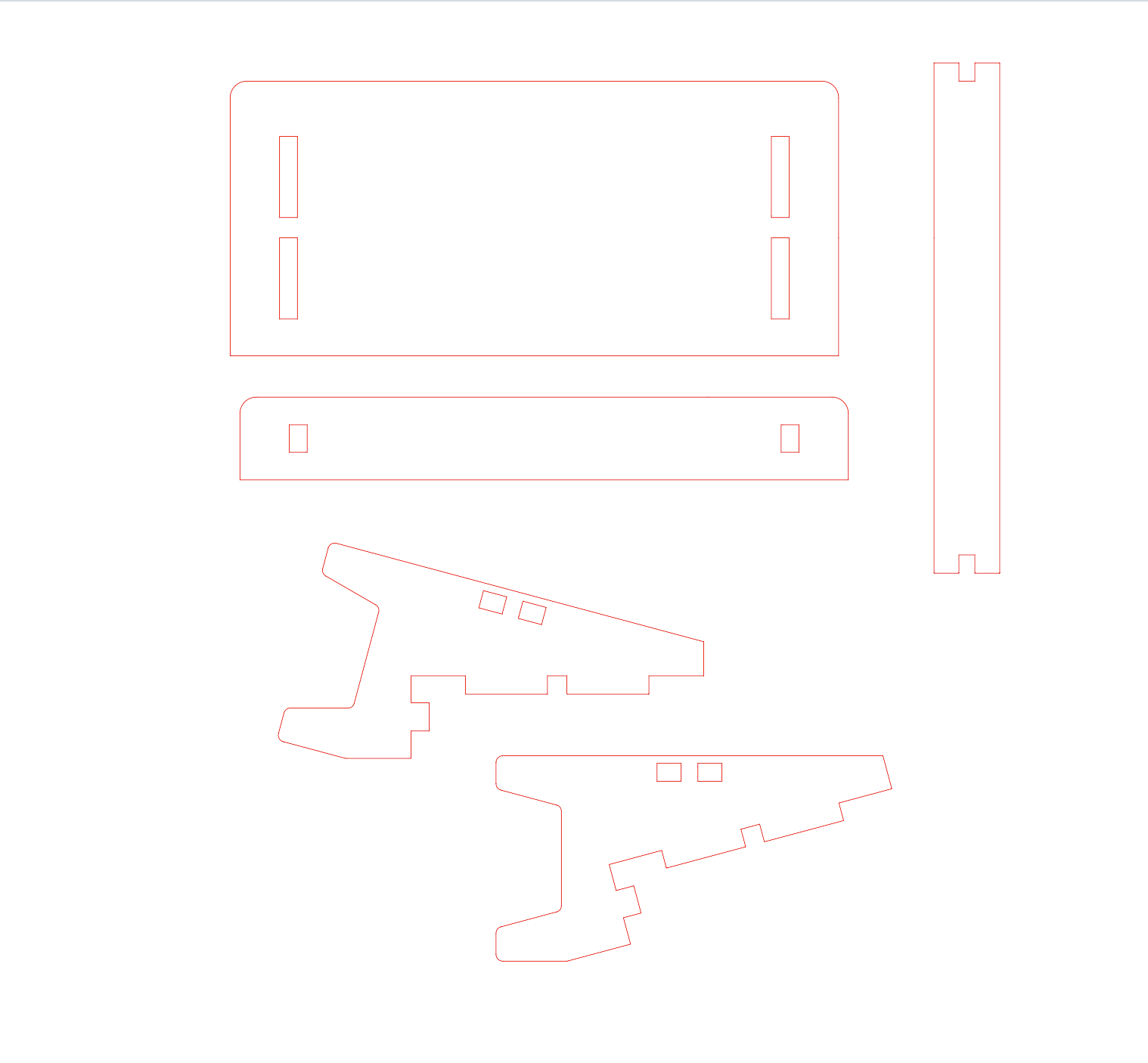
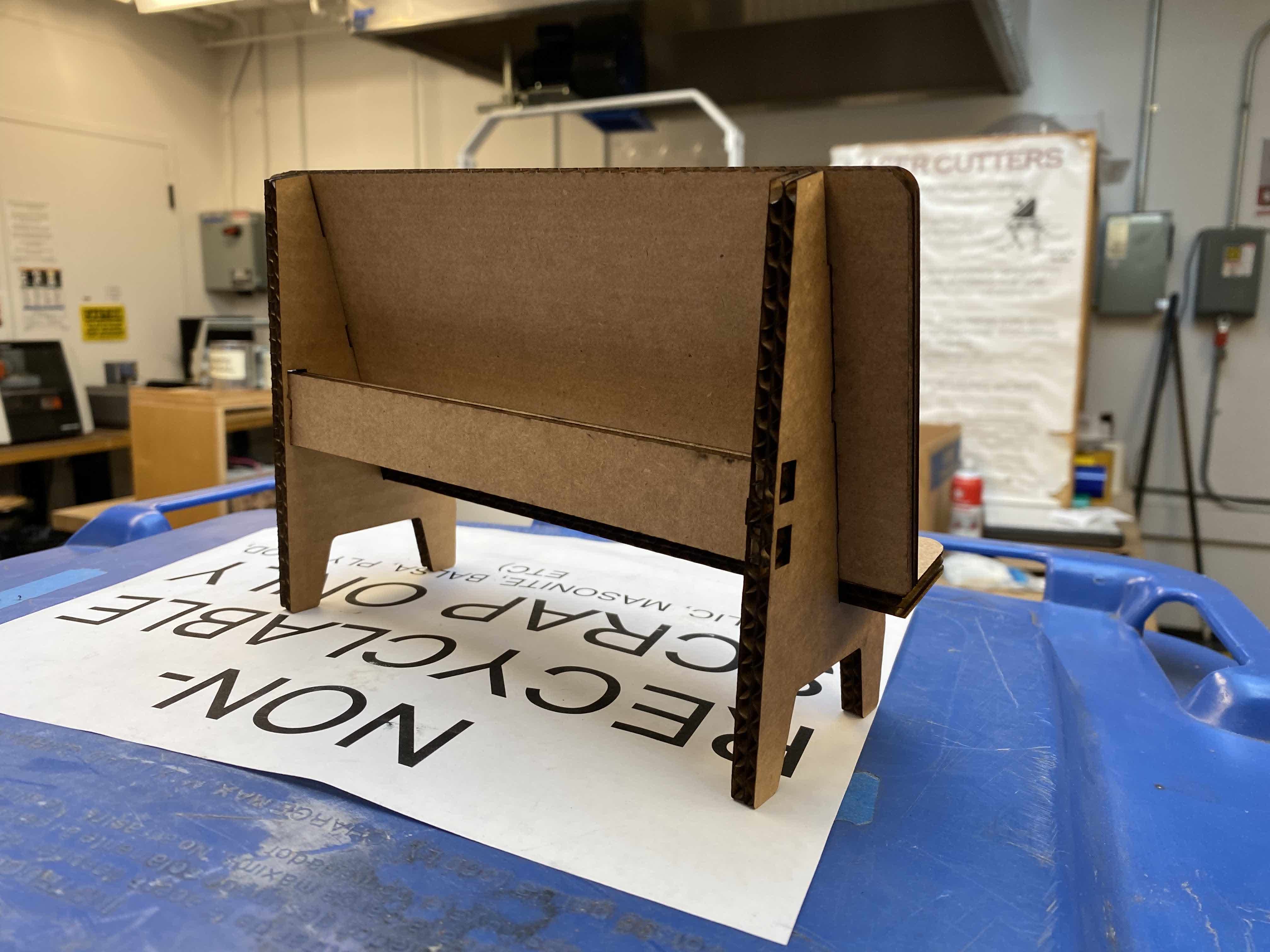
I decided to build a cell phone stand so that I can rest my phone up while I watch netflix and eat. I modeled my stand using Fusion 360, and I then exported a sketch as a .DXF file which I then imported into Rhino 7.
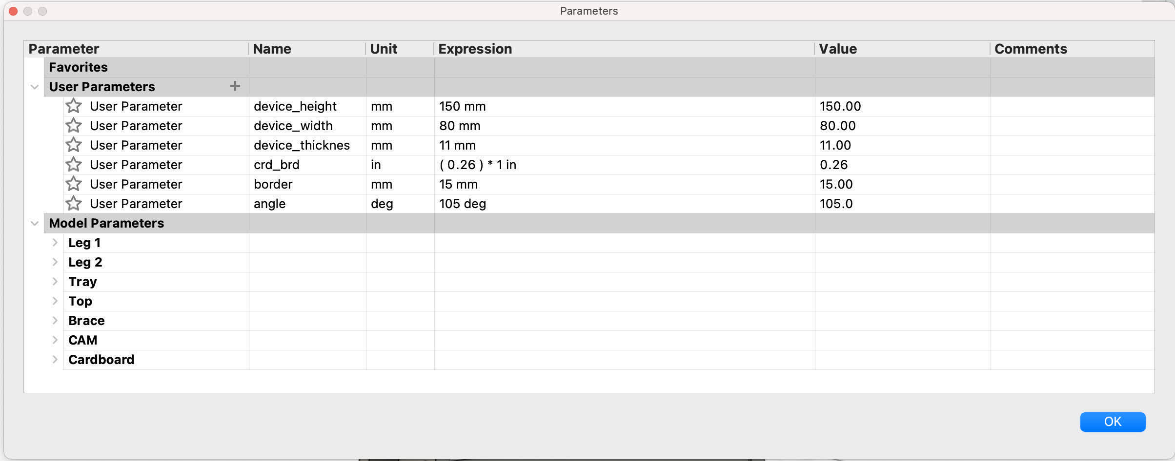
These are the parameters I defined for my stand. The idea was to make the design easly adaptable to different phone sizes and card board thicknesses.
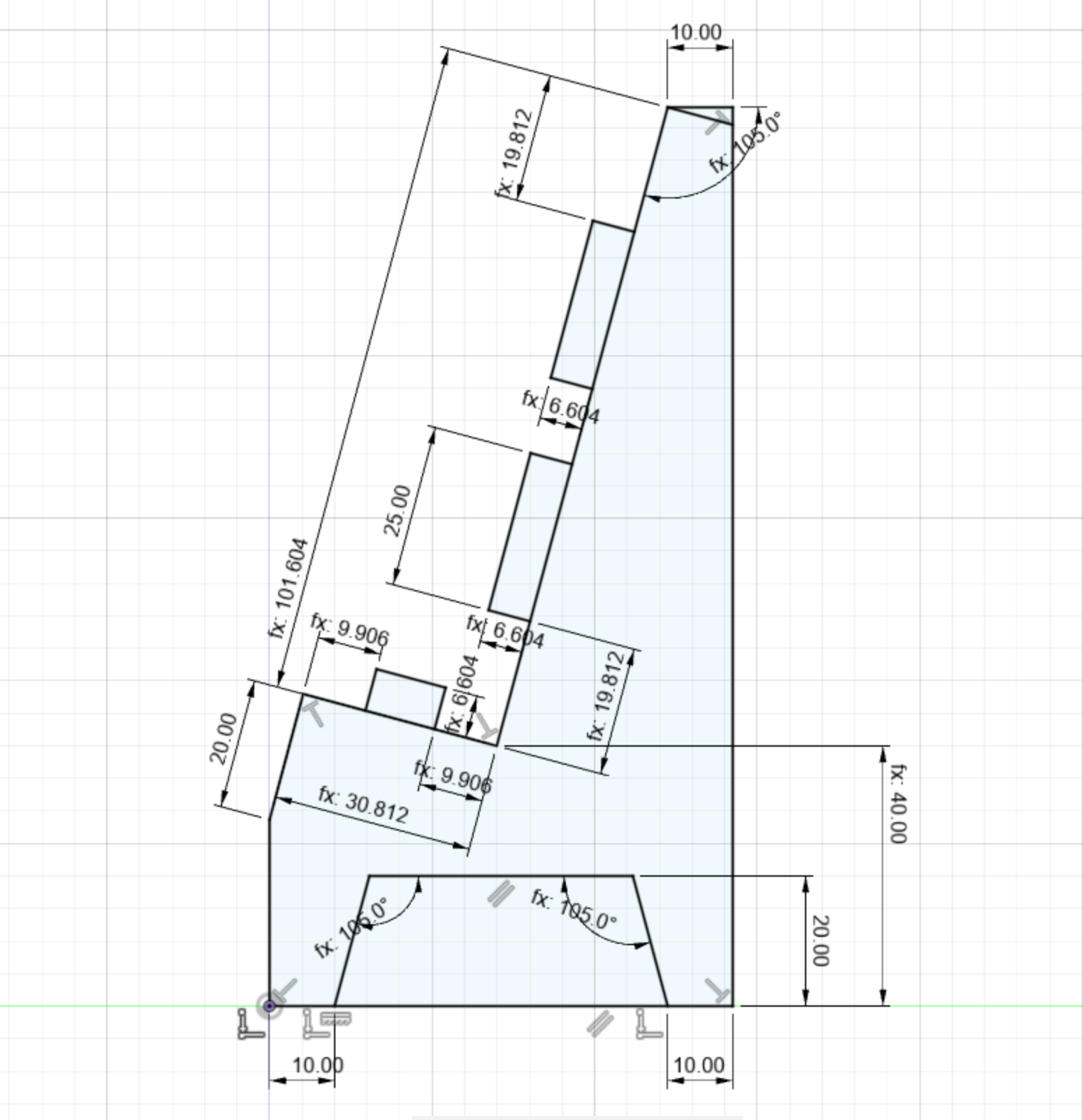
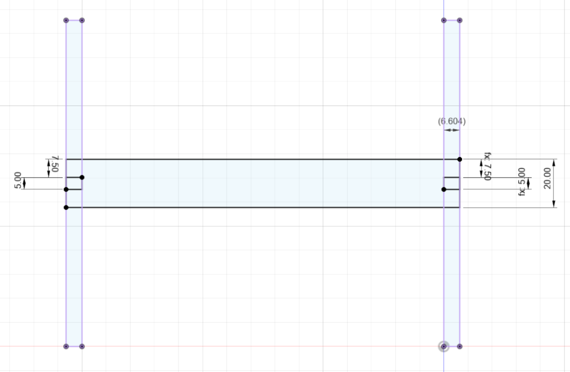
Here are two of sketches I made, one is of my stand's leg, and the other is of the back brace for my stand. I made sketches like these for each of my stand components.
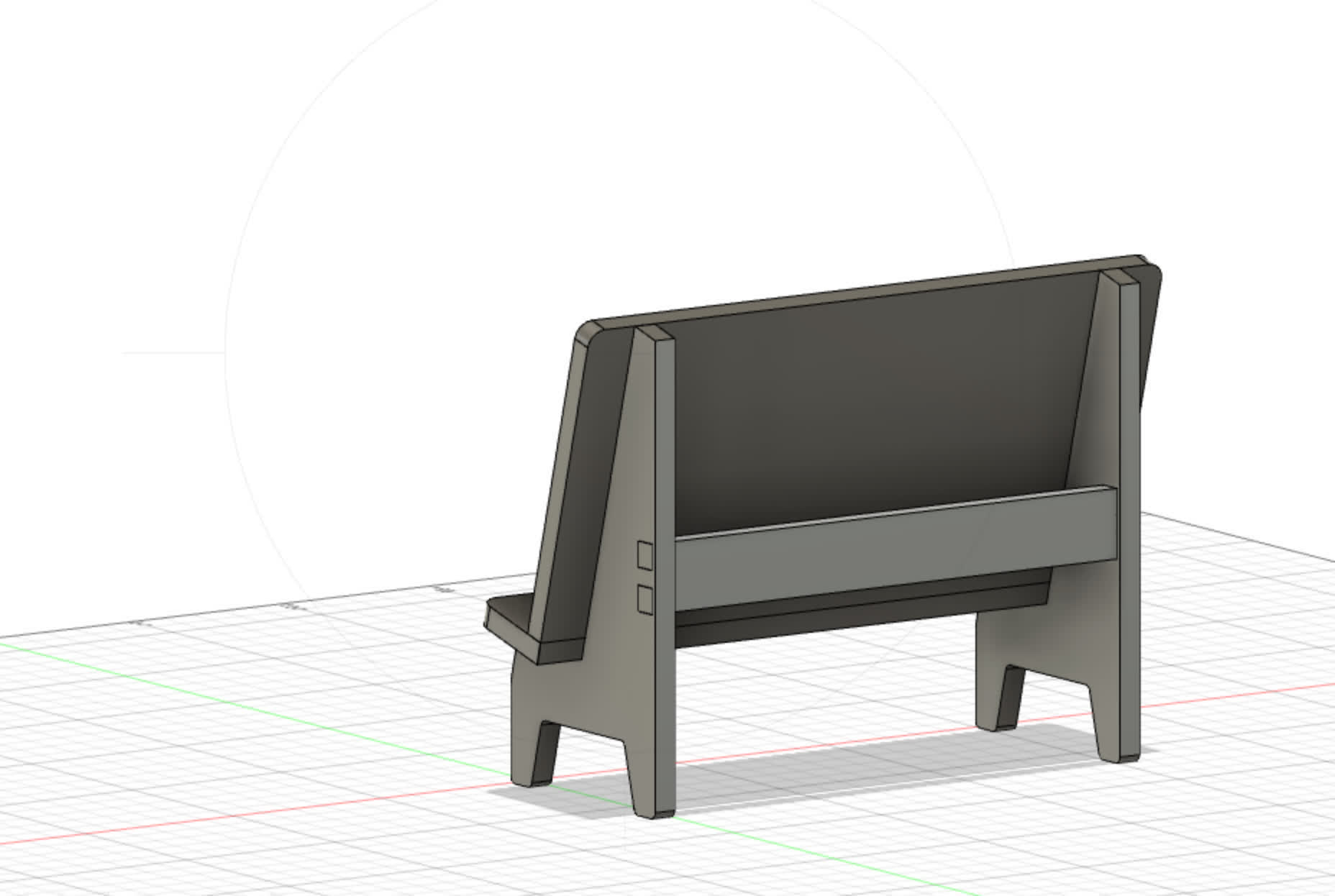
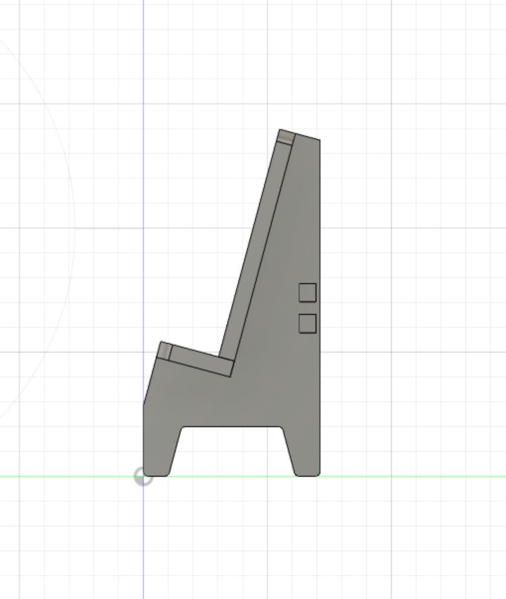
I then used the extrude feature to turn these sketches into a 3D model.
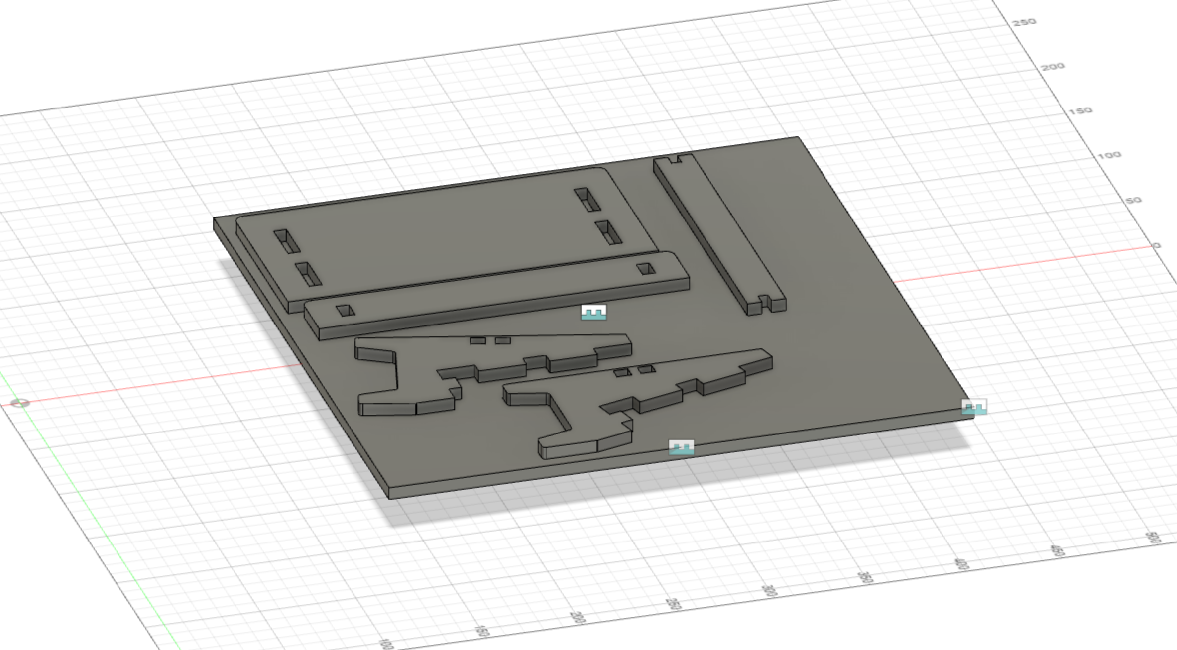
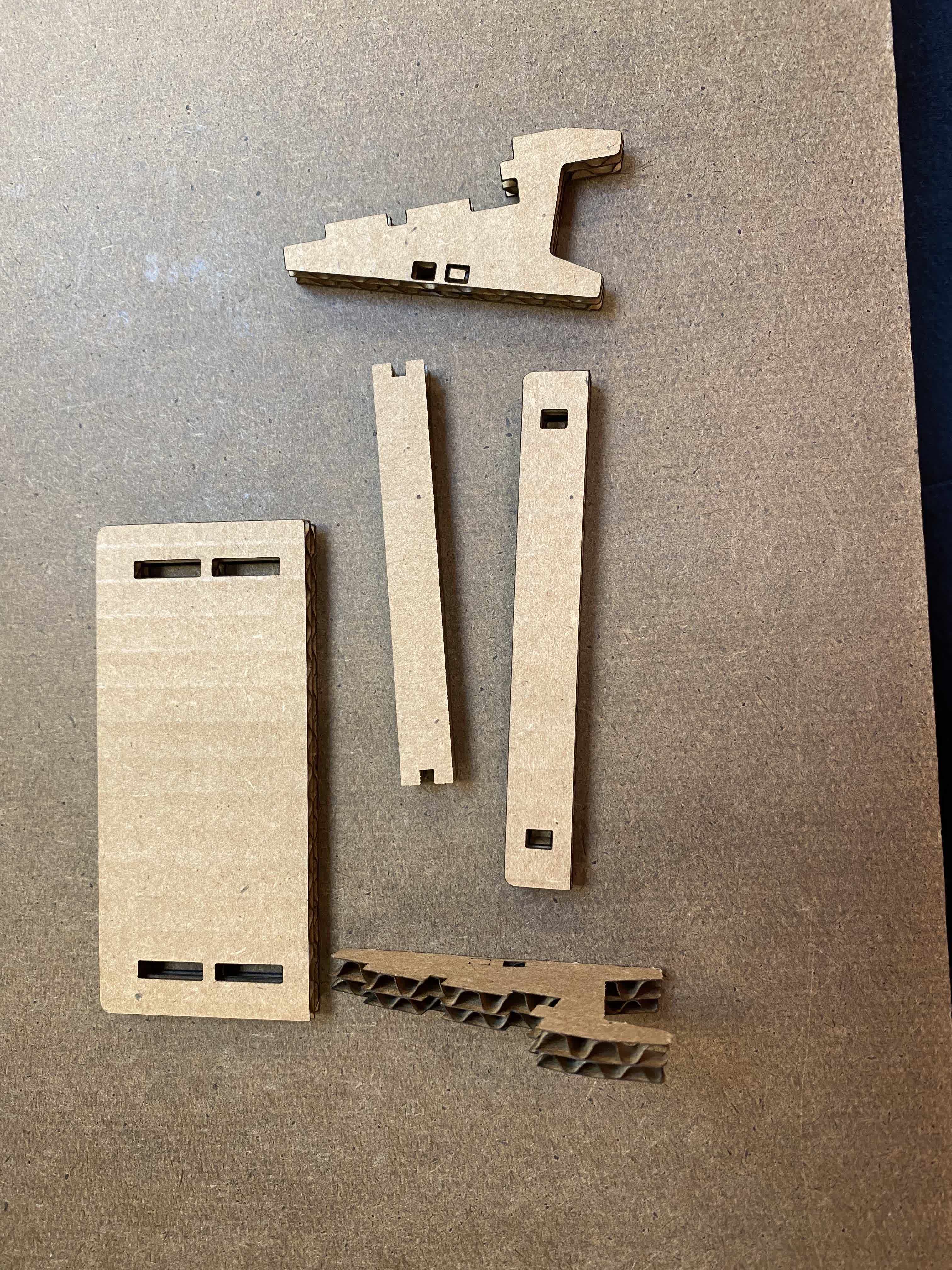
Once I finished my model, I created a clone of each piece and flattened them out. I then took a projection of all the faces, made a new sketch, and exported this as a .DXF file. This is what I imported into Rhino.
It was finally time to laser cut, and I totally got it perfectly right on my very first try! Just kidding. My first attempt, while it cut successfully, did not fit together at all. The issue was the hole sizes. While I had correctly parameterized the hole size in fusion to be based on the card board thickness, it turned out that Rhino was not reading the dimensions that I had specified, and it was assigning its own scale. This is not Rhino's fault, but rather a feature of .DXF files.
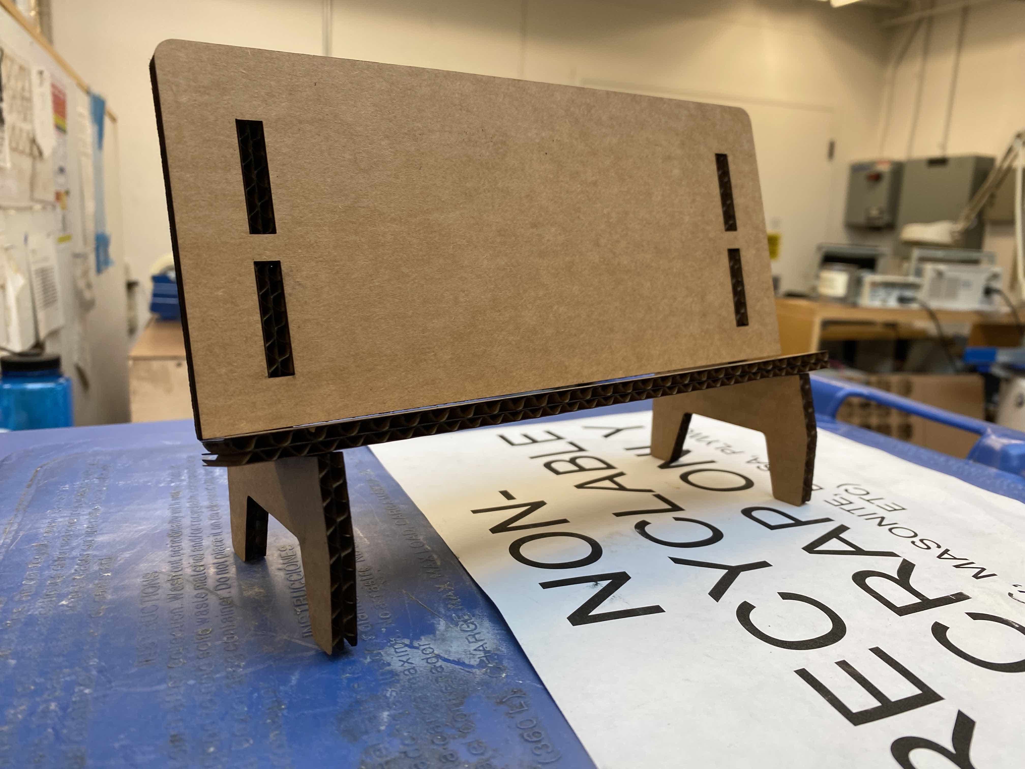
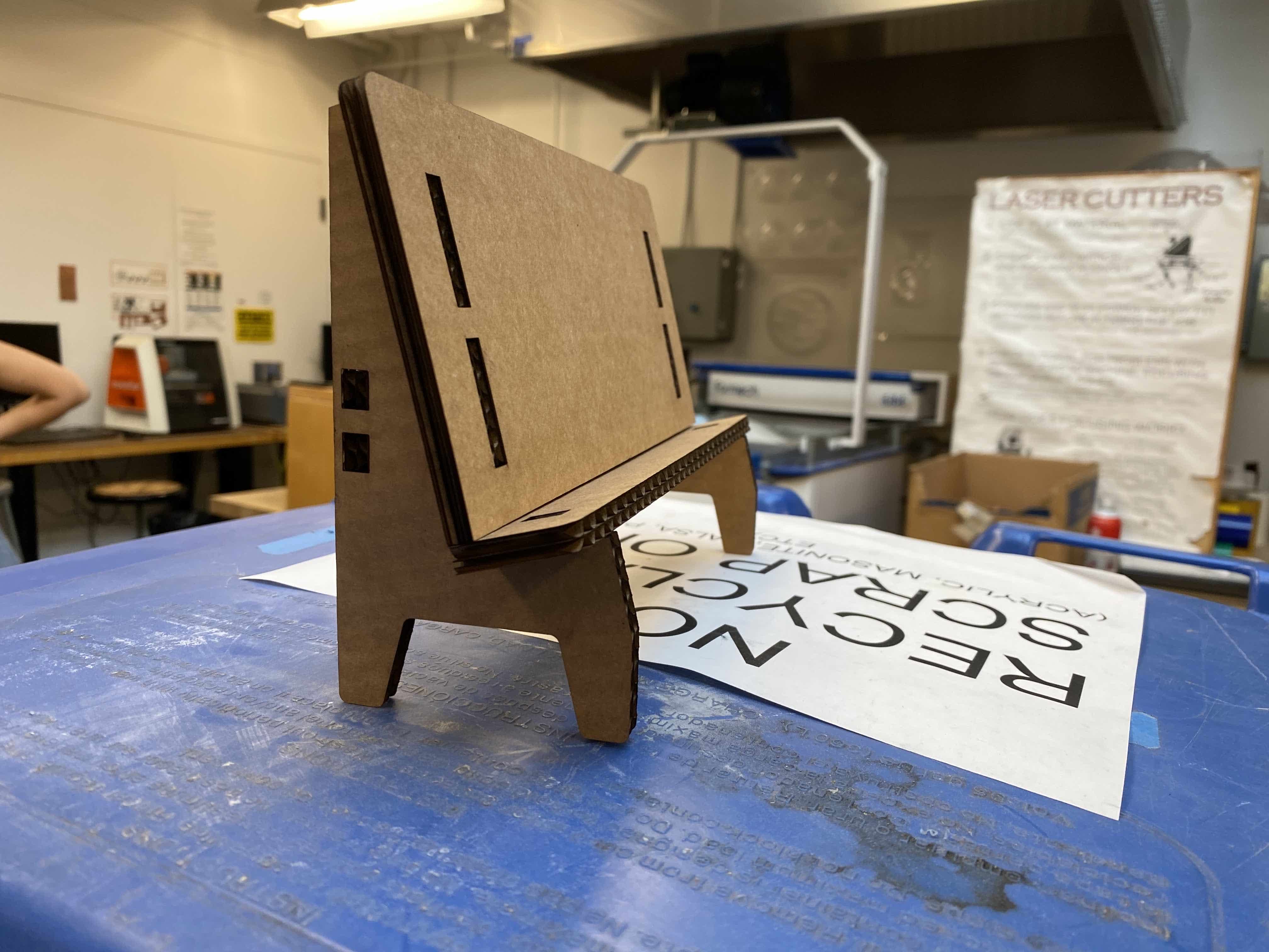
After struggling for a couple of days with this, one of my classmates easily pointed out that I had a scaling problem, and showed me how to rescale my model in Rhino. Basically I typed in the Scale function, drew a line between two points that I knew what the distance should be according to my original Fusion model, and entered that in. And like magic, it worked!
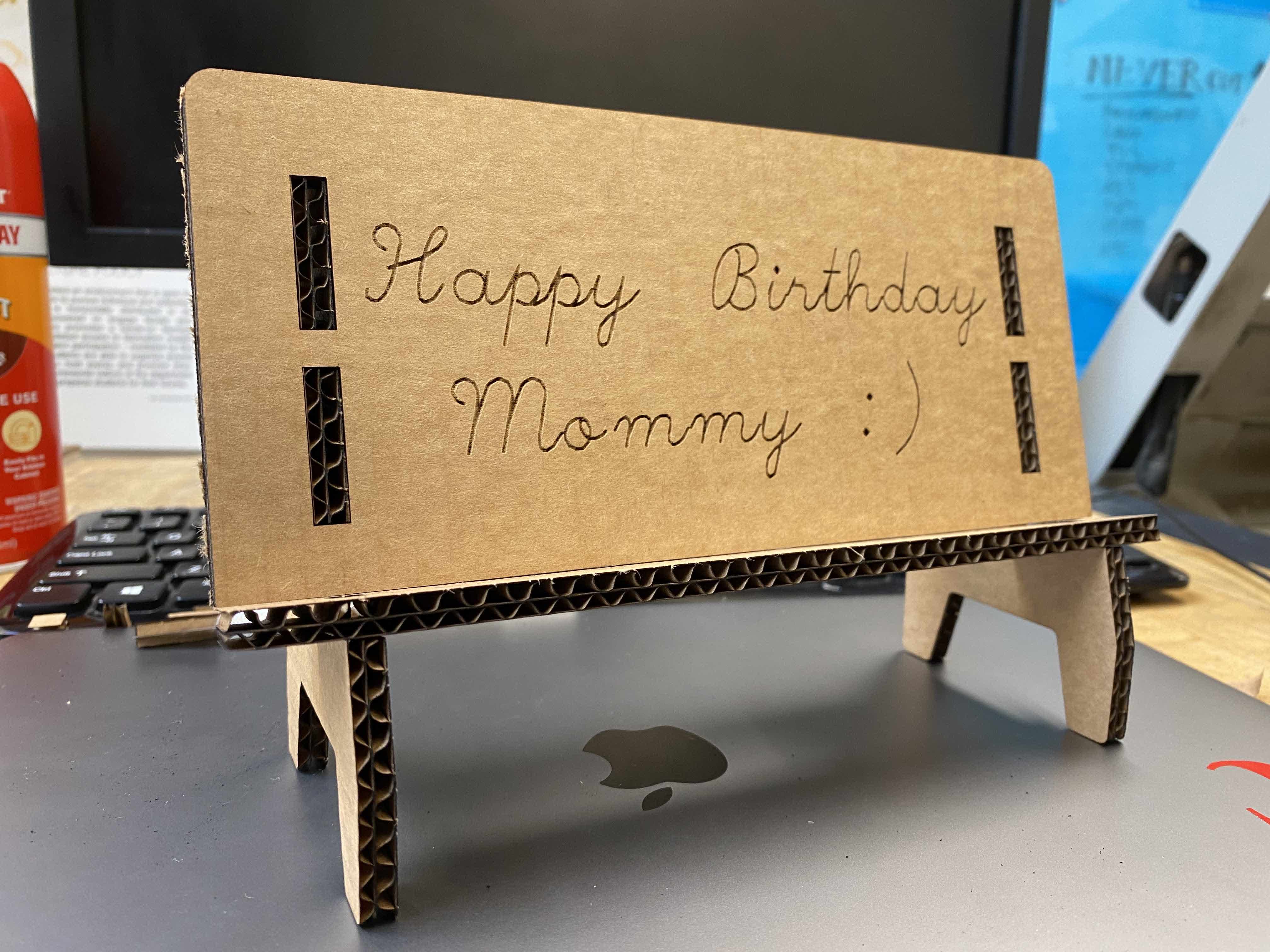
Finally, it's my Mom's birthday next week, so I wanted to make her a custom stand! I added Text to my Rhino model, and uesd the raster print feature to etch in a message. I made sure to do the rastering first before the actual laser cutting.