Group Assignment
Characterize the PCB Production Processs
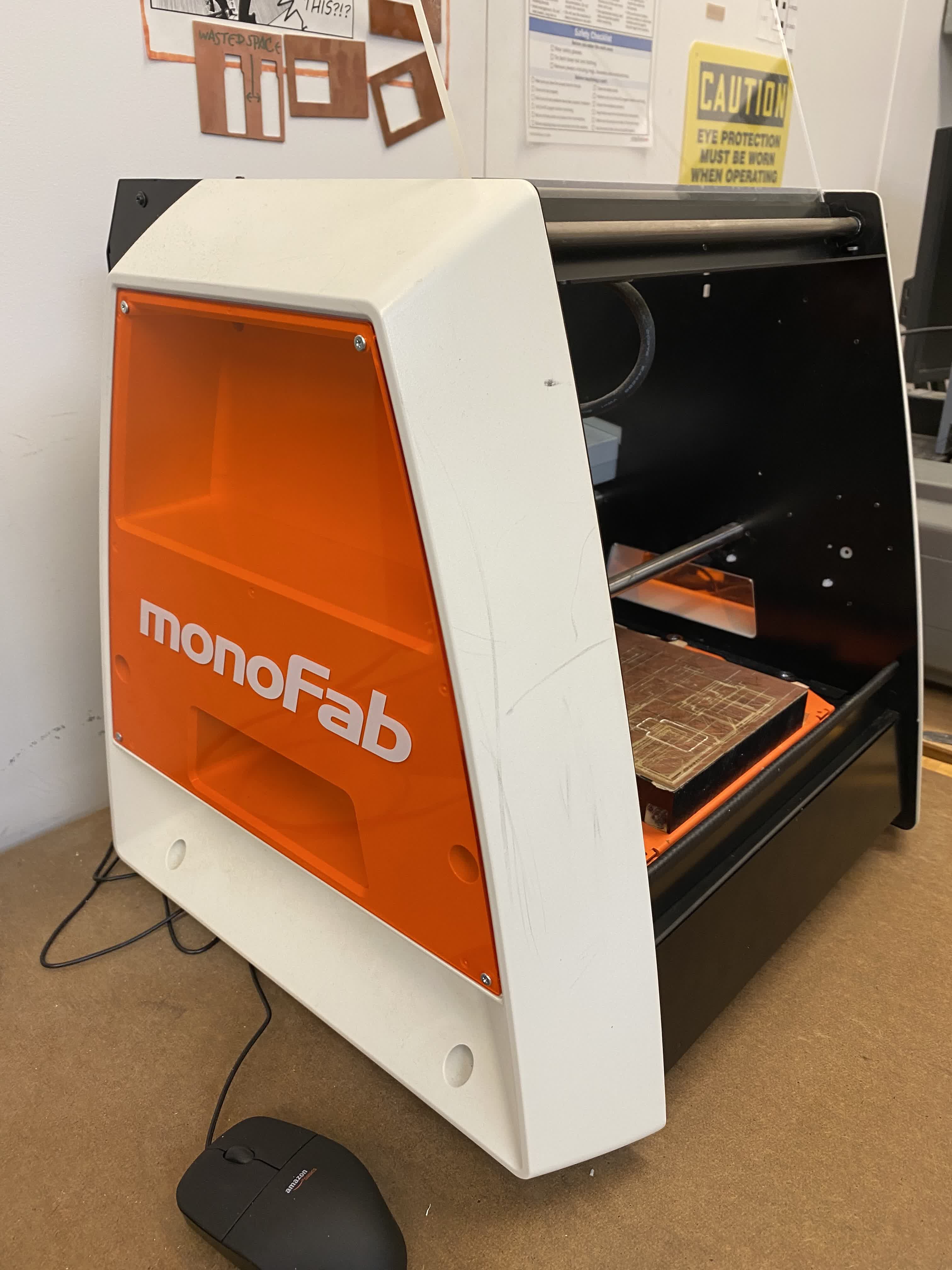
For this week, we learned how to mill and stuff printed ciruit boards (PCB)! In our lab we used the Roland SRM-20 milling machine, which we controlled using mods. For our group assignment, we had to understand the PCB production process.

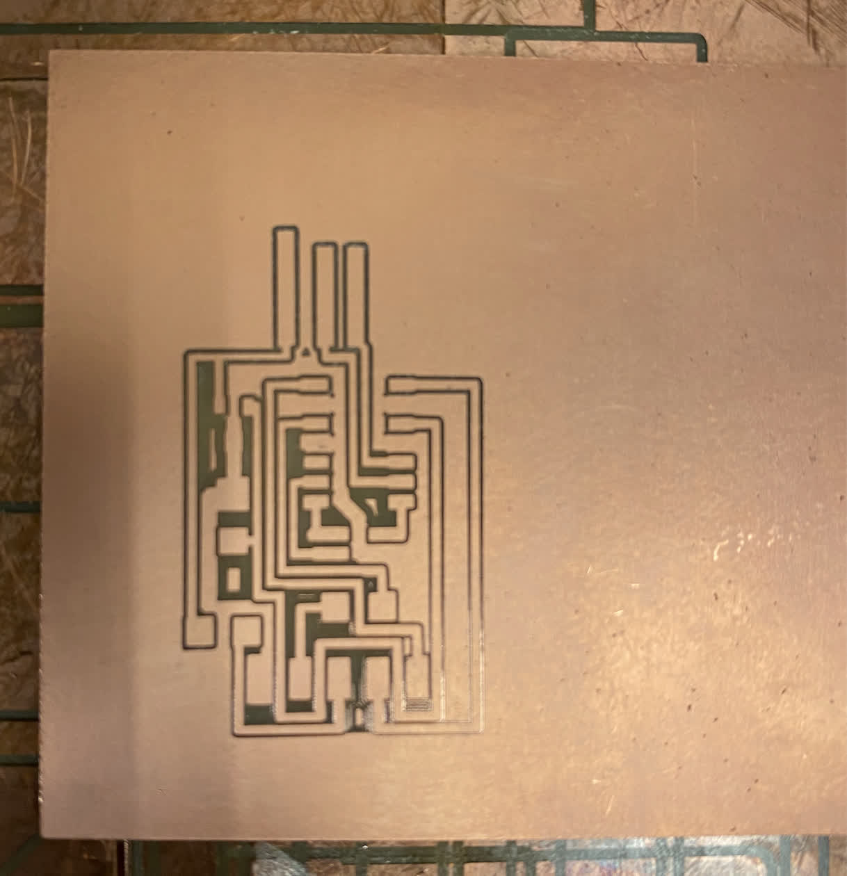
To do this, my group (myself, Bo, and Emily) started by milling the line test files (both traces and perimeter shown below). We used 1/64" endmill to mill the traces, and the 1/32" endmill to mill the perimeter.


Here is a short clip of the pcb being milled, and on the right you'll see our final product. From our results, we were able to get decently clear lines with the 1/64" endmill, but we don't think it's a good idea to go too thin because it may make soldering joints more difficult. The 1/32" endmill is too large for the internal traces, but it does a great job of milling the perimeter.

Individual Assignment
Mill and Stuff an In-Circuit Programmer
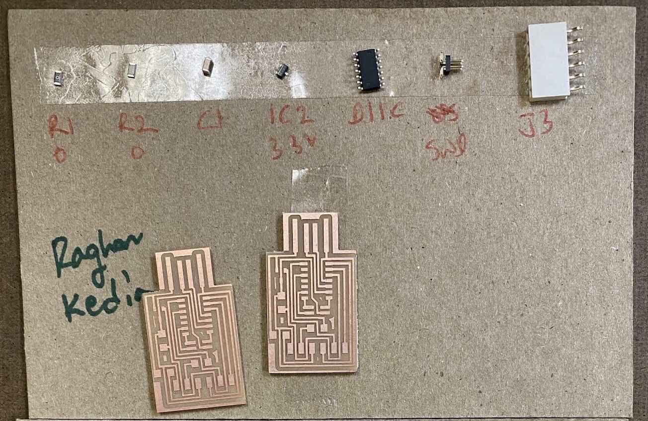
I milled a hello.D11C.serial.5V.1.1, which is a serial adapter for AVR chips using the D11C micro controller. Below you will see the traces and the exterior, as well as the components for the chip.


Failure.
My first attempt at milling this board ended in failure. As you can see, the bottom right side of the board does not have as deep cuts as the rest of the board (I stopped the milling right away once I noticed this). I correctly uploaded the file to mods, and I set the origin correctly.
Upon closer inspection of the failed board, the endmill, and the baseplate, I discovered there were two key mistakes I made:
- Board was not tapped strongly enough to the base plate. I should have applied more tape to the bottom of the board and pressed down very firmly to minimize as much gap as I could. This likely led to the inconsistent depth of cuts.
- The endmill was not secured tightly. I noticed there was a slight wobble in the endmill, which is not good. This could lead to inconsistent and wider cuts, and is likely bad for the endmill.
- (Bonus mistake): Ensuring that when I pull down the endmill to the board and retighten, making sure to make a concious effort to hold the endmill down to the board while I tighten.
Success! Time to Solder...
After accounting for my mistakes above, I succeeded in milling the PCB board! Next step was to solder and stuff the board. Below you'll see my board with all the physical components layed out. I used a cardboard and double-sided tape to hold all of the components and my board - all the pieces are so tiny and this helped me stay organized, and it also provided me with a stable working surface. Also, I decided to mill two boards so I can practice the milling process, and to have a backup board just in case I ran into trouble with soldering (highly recommend!).
Here are two timelapse clips of me soldering :) This was a stressful and tedious process, and I definitely need to improve my fine motor skills (if that's even possible at this point). But nonetheless, I persevered...
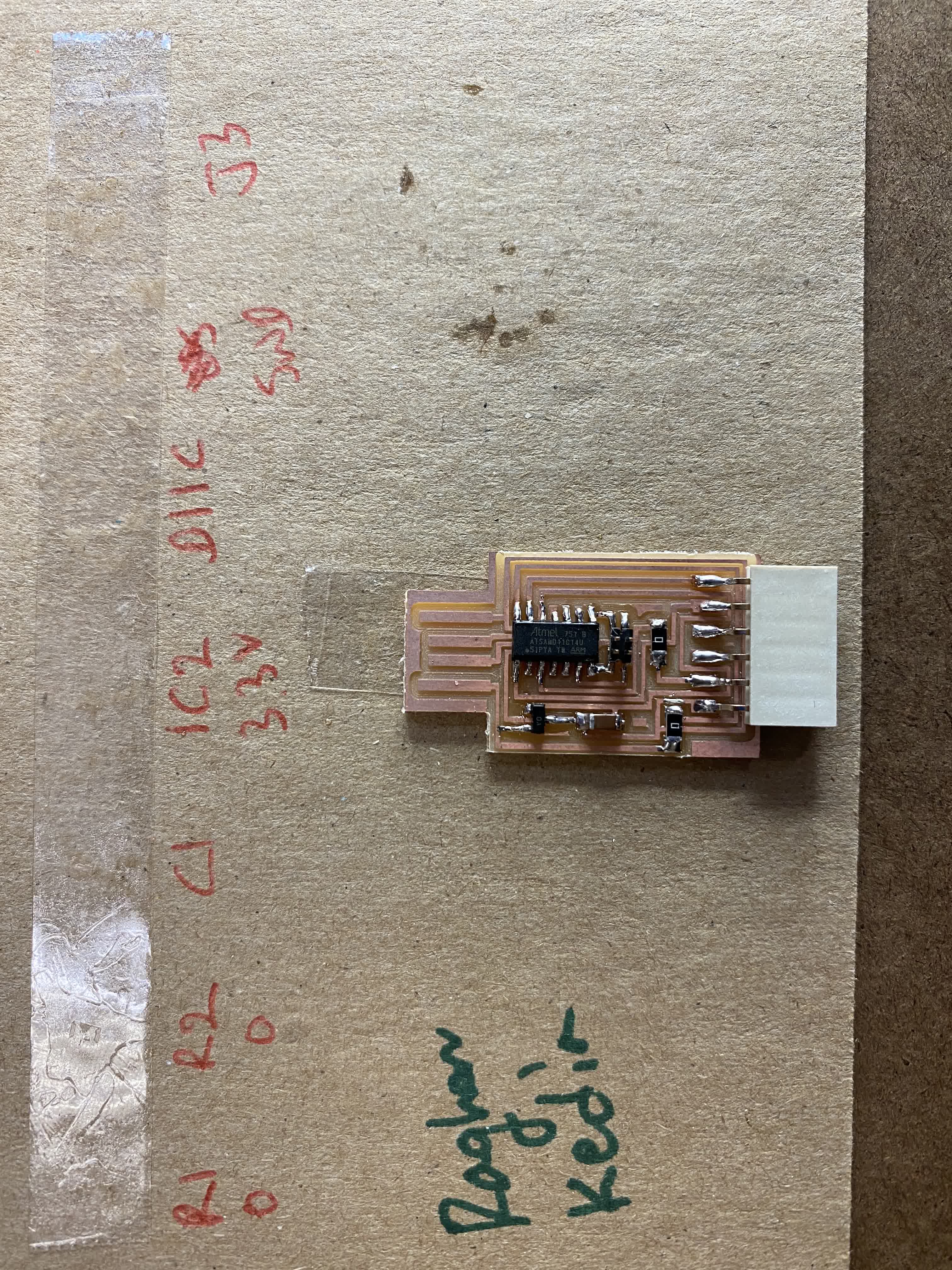
And eventually I finished! All in all, I'm quite pleased with the soldering. I eventually found that I got into a rhythm, and things (solder) just started flowing ;) You'll see my final product on the left, and a gif of how my board came together one component at a time. Notice how I started with the most interior components and worked my way outwards.


Testing the PCB
To test my PCB, I used a multimeter to verify whether current was flowing between points on the circuit where it should be (and just as important, to verify that current was not flowing where it should not be). I used the two tips and connected them at various points, and the multimeter would make a "beep" sound if current was flowing. Luckily I found that for both of my boards, all of my solder joints were secure.
