Group Assignment:
Individual Assignment: Design and Cast a Mold
Mold Design: Shock Absorber
For this week we had to design and cast our own mold! I knew immediately that I wanted to design a custom MIT shock absorber for tennis rackets - I'm part of the club tennis team, and I thought it would be cool to make a bunch of these for the team. If you're not familiar, a shock absorber is a small rubber piece (usually made out of silicon or PVC) that you put at the base of the string bed to give the racket a more "deader" feel (you feel less vibrations in the hand). I started by designing my piece in fusion. Since I want my piece to be made out of rubbber, I actually want my end product to be made out of the oomoo (in practice, oomoo is too soft for a shock absorber, but it's all I had access too). Therefore, instead of carving the positive into the wax block, I needed to cut the negative so that I can pour oomoo in and get my desired piece out. I also realized that I don't need to design the full piece, but just 1 half of the piece since it is symmetric and I can just cast the face twice. Here is what my design looked like:


Since my piece will be really small (dimensions are approximately 22mm x 22mm x 4mm), I decided to mill my wax block with the Roland SRM-20 mill rather than the shop bot. This was also a great excuse to test out the 3D milling feature that Neil just added in mods. Another big benefit of this was that I did not need to worry about configuring multiple tool sizes/paths. All I need is (optionally) a rough cut with a larger tool bit, and a finish cut with a finer tool bit. More on this later. This mods workflow took as input an STL file, so I exported my CAD design to STL:


Setup in Mods
Setting up my file in Mods was by far the most challenging part of this whole week. I had a whole back and forth with Neil and Anthony in a gitlab issue ironing out the kinks. Please look at that issue for a detailed description of the issues I ran into. For now, I'll show some screenshots of the problematic toolpaths that Mods was generating for me:


The issues above were caused by a combination of my face not having a border lip, and the orientation of my face being backwards. My original CAD design did not have the border lip that is featured above, which is what was causing all my toolpath issues. After adding my lip, mods was now outputing the correct toolpath:


And here are what the mods workflows looked like (mill 2.5D on left, and mill 3D on right):


Milling the Wax Block
With Mods all setup, now was finally time to mill the block! Per Neil's suggestion, I started with an air cut to make sure the machine executed the G-code to completion. This was one of the first times actually testing the 2.5D/3D milling workflows on the Roland, so it was important to do an aircut. This is an aircut of the 2.5D milling, so a rough cut. This is with a 1/8" bit. Here's a clip:
After the aircut finished successfully, I lowered the bit to the wax and ran it for real. Here is a clip of the actual cut, and the results after it finished:


As you can see, the result of the rough cut was not what I was expecting. It's almost as if it milled the inverse of what I wanted. For example, it left the text alone so it is pointing upwards instead of downwards. At this point I decided not to spend time and figure out what went wrong, but instead I decided to just skip the rough cutting step and do just the finishing step. This is because I saw the toolpath that the 3D mods was outputting, and I was more confident in that working correctly. So I switched to the 3D workflow, moved the bit over to the right, and swapped out the 1/8" bit with a 1/32" bit. Importantly, I decided to use a ball-end 1/32" bit initially. Here are the results:


Much much better! At this point I was quite satisfied with the result and I shared it with Neil. He immediately noticed that this was milled with a ball-end mill, and he suggested I use a flat-end mill because "they leave smoother horizontal surfaces, and can also do smooth curving surfaces with a three-axis toolpath (as well as cutting more efficiently)." So I remilled the same piece with the same workflow, but this time with a 1/32" flat-end mill for comparison. Unfortinately I don't have any pics of the flat-end milled mold alone.
Casting with Oomoo
With my molds ready to go, I could finally move on to casting with oomoo. This was actually really straightforward - I just followed the package instructions. I just needed to mix (thoroughly!) equal parts of the part A solution and part B solution. I used a scale to make sure I poured equal parts:


After mixing, I poured the oomoo into all of my molds.

After waiting 90 minutes for the oomoo to cure, I then peeled out my casts:


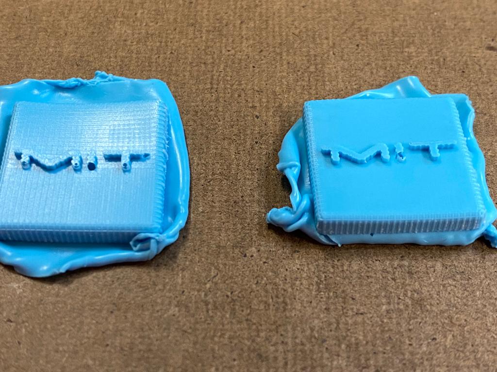
And here is a pic of the ball-end mill cast (left) vs. the flat-end mill cast (right). That flat-end mill did indeed result in a smoother surface. Also, I used an exacto knife to cut off the excess oomoo around the edges.
Lastly, I had to fuse the two faces together. I must say that I improvised this part. I cut out a small hole in cardboard, and then divded the cardboard piece in half. My idea was to lay both pieces on the back side on one of the faces, pour in a small amount of fresh oomoo, and then place the other face on top (so the two faces would be back to back). This would work in theory because silicon fuses to silicon. I had to divide the piece in half so that after the new oomoo cured I could seperate the hole piece.

Final Product
After after the new oomoo cured, this is what I was left with:


It's definitely a little rough around the edges, but overally I'm quite pleased with this as a prototype. Going forward, I would definitely use the flat-end mill. I would also use a large piece of card board when fusing the two faces toghether to prevent oomoo from spilling off the sides. Lastly, I'd like to use a harder silicon.
Of course I had to test it out!


Files
Fusion Design FileShock Absorber STL