Group Assignment: Probe an Input Device's Analog Levels and Digital Signals
Big thanks to Bo for figuring out the group assignment for us! She used an ultrasonic distance sensor and a button as her input devices.


Individual Assignment: Add a Sensor to a Microcontroller Board
The Humble Button
For this week we had to add a sensor to a microcontroller board that we designed and read it. It was also Diwali this past week so I was back home in NY this weekend with my family! Though this did mean that I did not have much time to experiment with a fancy input sensor. However, as the end of the semester is approaching, I need to start making tangible progress towards my final project. Turns out, for my final project the only input device I really need is a button (or two). I will also need to be controlling two servo motors, and I want all these to be controlled from a single microcontroller - the D21E. Therefore, for this week I decided to make a dev board where I will expose all of the pins on the D21E, and then make a seperate button break out board. For exposing the pins, I decided to use the 6x1 FTDI pin headers that we have in the shop. This was simple since we also have these footprints in the fab library.
Here are my schematics and board designs:
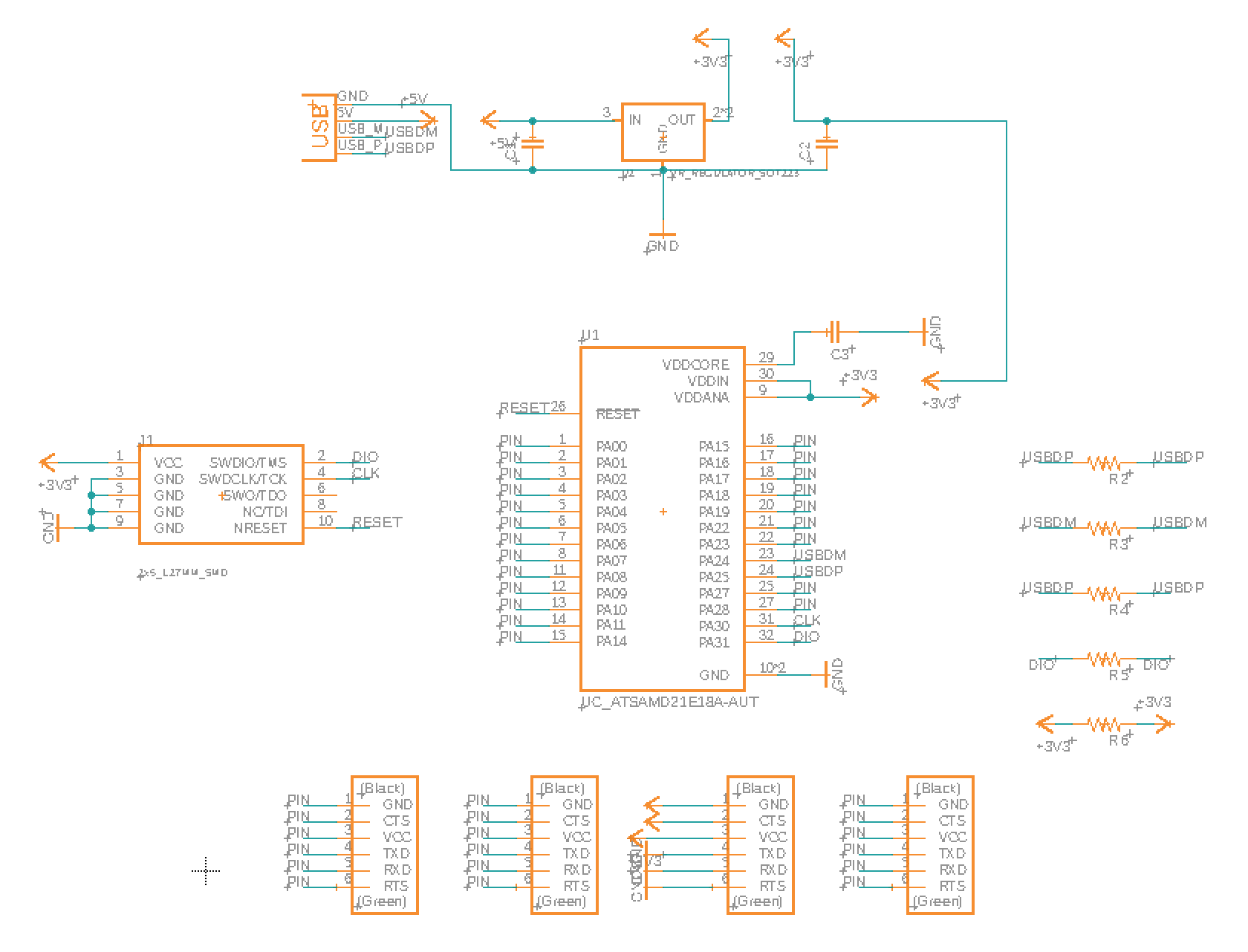


In addition to exposing a lot of the digital and analog pins, I am also exposing 5V on two pins, 3.3V on one pin, and GND on three pins. It is critical to expose GND so that for all the boards that I connect to my dev board I can have a common ground. Hopefully I can power my two servo motors with the 5V from USB, but we'll see about this. I may need an external power source.
Milling them was straight forward. This time I made sure to export at 1500 dpi so that mods will be able to mill through the pads on the D21E. For soldering the D21E, I wanted to try using the solder paste and heat gun. Anthony helped me with this, and overall it worked great; I just had to do some fine tuning on a couple of pads. Here is how the board turned out:
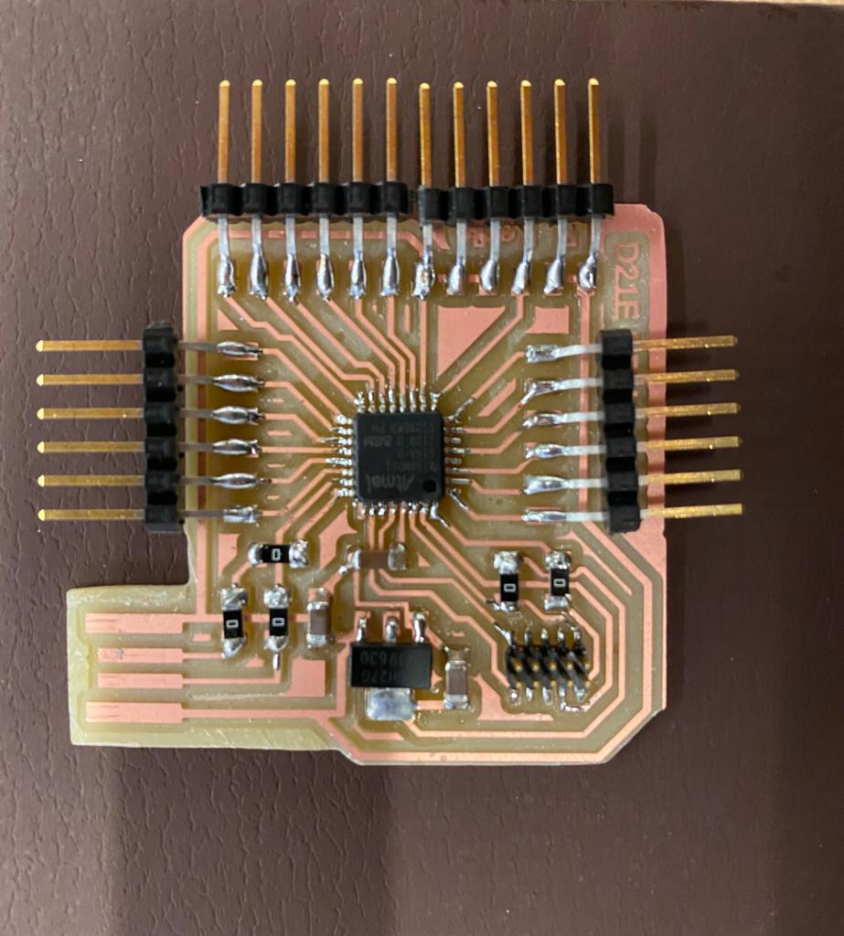
In hindsight, I wish I did not place the FTDI headers so close to the USB end - this made it tricky to fit into USB ports. Ideally the pins would be pointing upwards instead of outwards also, so I may go back and remove the pins, bend them up, and then reosolder them down.
Anthony helped me load the bootloader onto my board. Thankfully, and much to my surprise, the bootloader loaded perfectly on the first try.
And here is how the board looks when connected to my button breakout board. As you can see, I am connected GND (the brown wire), and the blue and green wires are for the two buttons.

Finally, I tested my board by loading a simple button test program (code file below), and observing the Serial Monitor in arduino:
Files
Dev Board Traces (remember to set DPI 3000 in mods!)
Dev Board Outline (remember to set DPI 3000 in mods!)
Button Board Traces (remember to set DPI 3000 in mods!)
Button Board Outline (remember to set DPI 3000 in mods!)
Button Test Code