Electronics Design
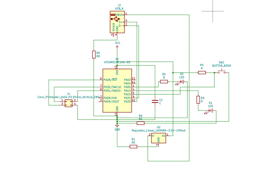
Two weeks ago, we learned about how to mill a PCS. This week, it is time for us to try out designing the schematic ourselves. I used KiCad for drawing the schematic and generating the components' footprint. The microcontroller I chose is the AMCD11C, which is the same one I milled two weeks ago. We were also asked to add at least one LED and one button. After importing the libraries, it was quite easy to get the components added to the schematic. The most difficult part was to layout the footprint, where paths cannot cross. I spent 4+ hours tweaking and reconnecting, and it felt like a mental gymnastics.
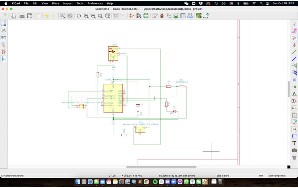
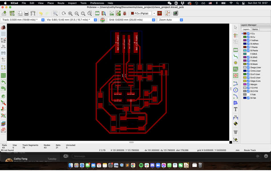
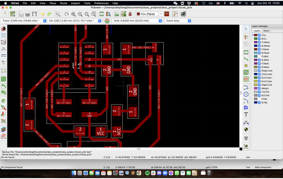
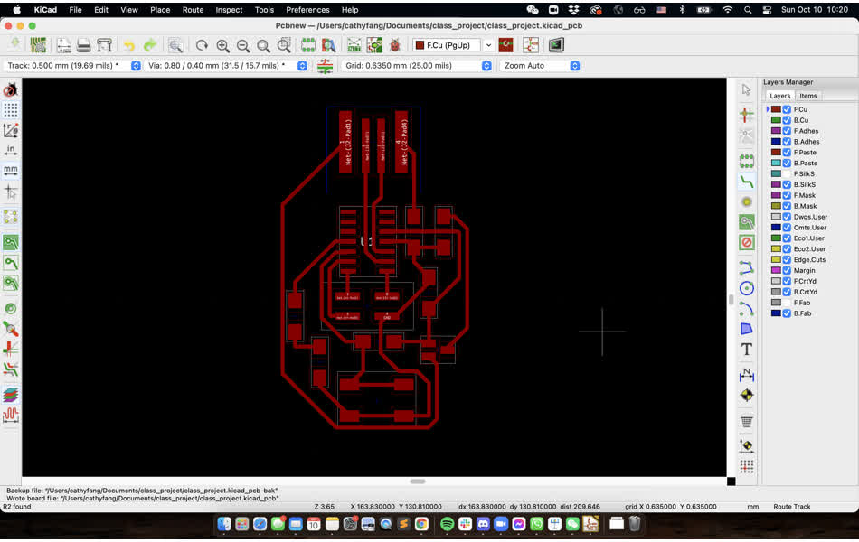
After I got everything connected, I couldn't help to clean it up a little and then realized there were some redundant components and wiring (Left). The final footprint looks like this! (Right)
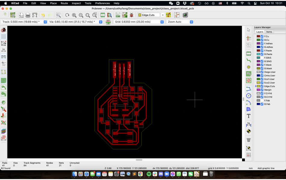
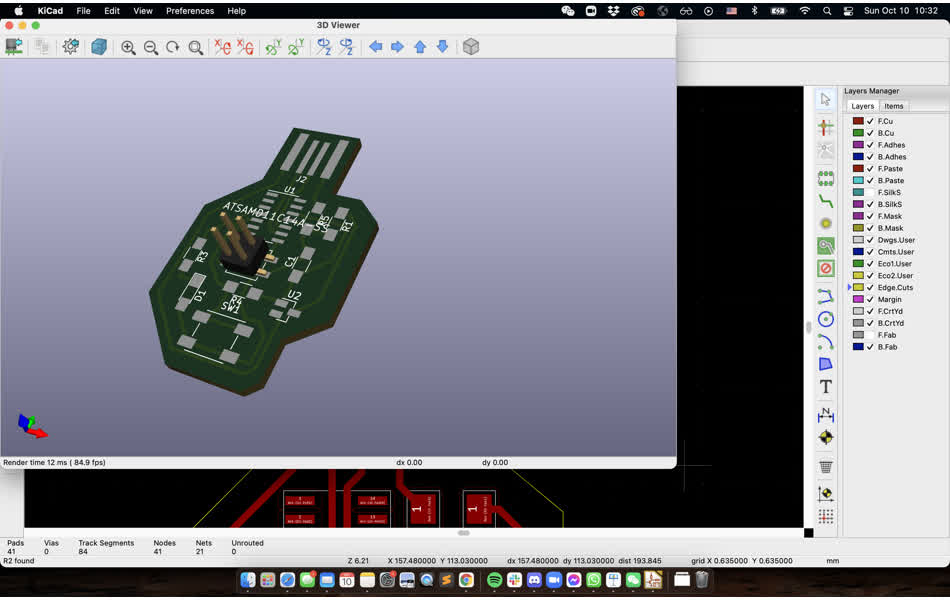
Now I need to draw the outline (in yellow). The 3D preview is pretty cool!!
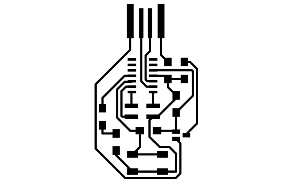
Time to export the svg files. So I used Inkscape to generate one for the traces and one for the outline. Initially I had some trouble loading it up in mods. Then I realized the svg needs to have a white (not transparent) background to allow the design to be inversed.

Now on the Roland milling machine. See week 2 documentation for the step-by-step process. I set up the mods and did a first mill with only one offset because I just wanted to get a sense of the traces. The traces look good but then I realize I didn't know how to skip the first offset. So I had to start over.
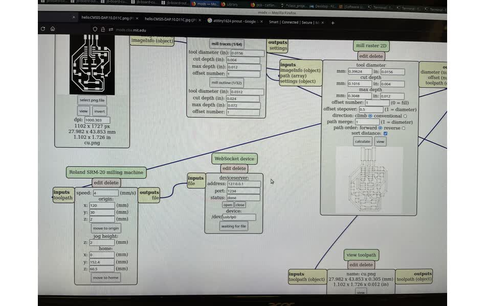
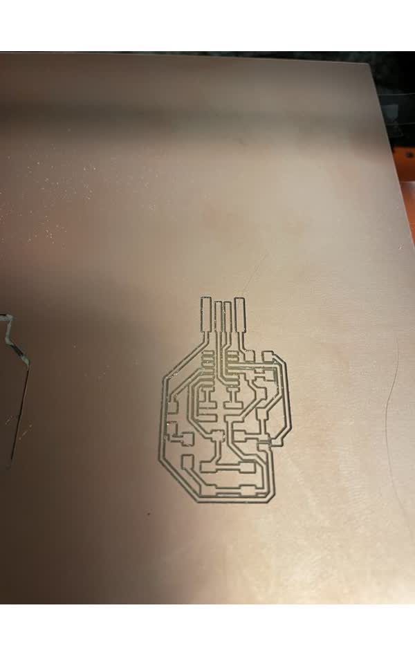
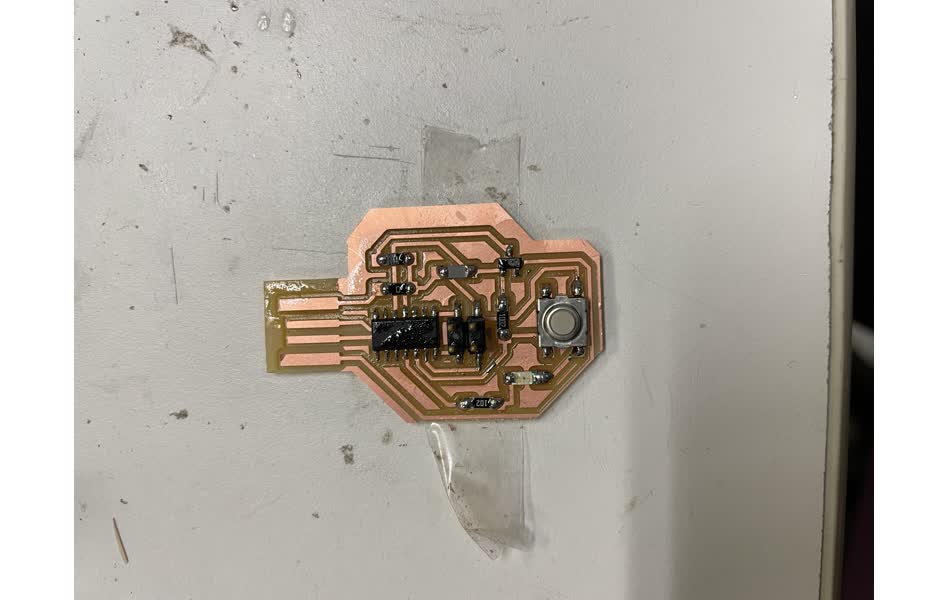
So I milled on a different part of the board and set the offset to 2 and max depth to be 3x the step. In the middle of milling, I noticed the board wasn't taped down completely, and I was worried the milling bit would be ruined. Luckily, it survived. However, as I started to mill the outline, I realized I made a critical mistake. I forgot I had changed the svg page margin only to the outline during the export process, so my outline was shifted to the right by 1mm.
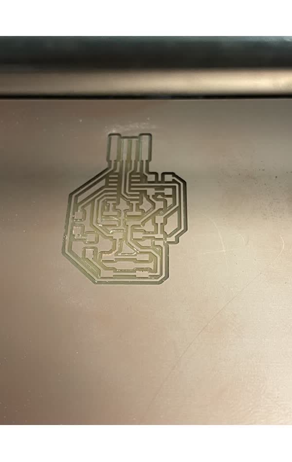
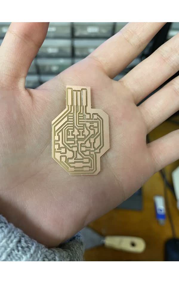
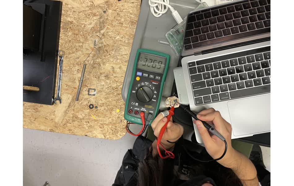
I am very worried that the left most trace that got cut away would be quite thin, and that is a critical path (from USB 5V to the regular Vin). I carefully soldered the components on. Besides the components from week2, I added a push button with a 10k Ohm pull-up resistor, an orange LED connected to a 1k Ohm resistor. I carefully removed the copper strips at the tip. To make sure everything was done right, I tested the continuity to make sure there wasn't any shortage. I added a layer of cardboard to the USB port to avoid adding bending stress. I also plugged in the board and tested the voltage after the regulator, which read around the intended ~3.3V.
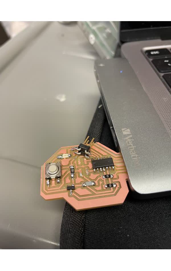
Just as I thought I was done, we were told that the 4pin header did not work directly with the programmer. I also accidently yanked off the 4pin header so I had to do an emergency soldering. Our TA Zach made a converter board, which my teammate Justin and I spent about 3 hours trying on our machine and couldn't figure out why it wouldnt work on our Macs. I thought maybe there was something wrong with my wiring but my continuity checks did not find any error. And with any hardware debugging, you somehow just need to try something illogical, such as switching to trying on a Linus machine...
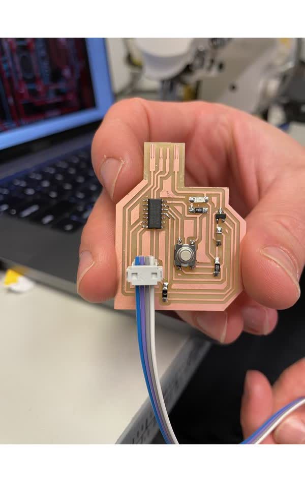
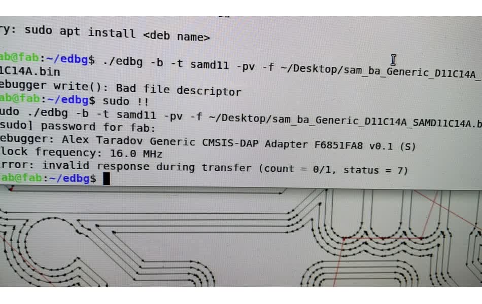
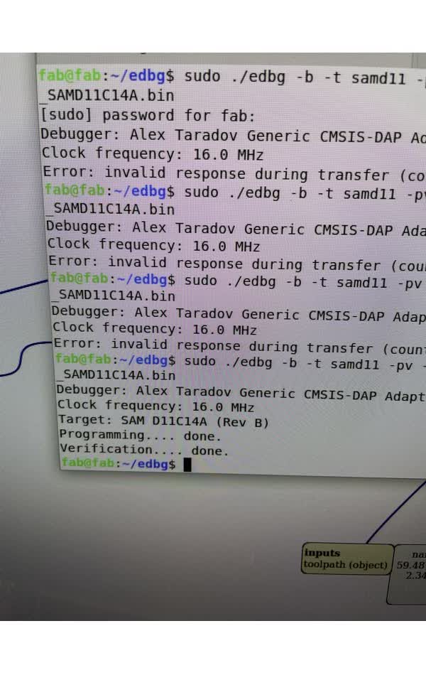
So to do the bootloading, you would need to do a series of backend complier magic. First you need to get the binary file for the microcontroller (MCU), in my case was the SAMD11C. Then you need to download the binary command line utility called edbg . Finally, you need to run this command at the location of your edbg binary file to bootload your board: "sudo ./edbg -b -t samd11 -pv -f [your path to SAMD11C binary file]" After all of that I still got an error, which after searching online seems to be due to bad connection. Based on past experience, I just shoved the board really tightly and held it during the bootloading, and it worked!!!!!!
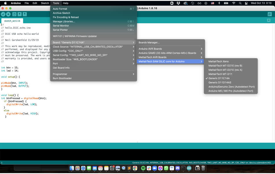
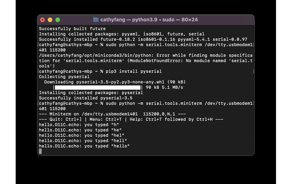
Finally, the rest is just to write program the board. For IDE, I used Arduino because it is what I am familiar with. First, I need to download the MattairTech SAM D|L|C Core library to the Board manager. Then configure everthing as shown in the image. The board should show up as a new port. On the right, upload the program that allows the serial output echos what the user types.
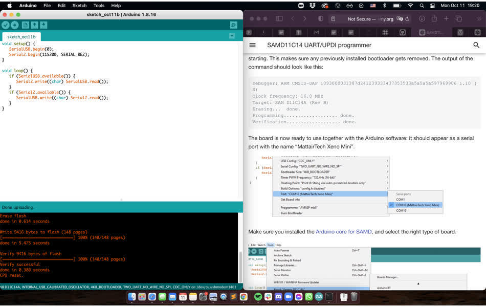
Now when I type "hello" it echos back to me. How cute. Next I programmed the LED to light up when I press a button. Somehow I reversed the direction, so I just changed the code to write "LOW" when the button is pressed. Nothing feels more timely then me sending out an "SOS" in morse code after spending so many hours on this stupid little board...
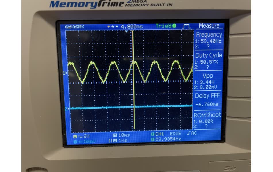
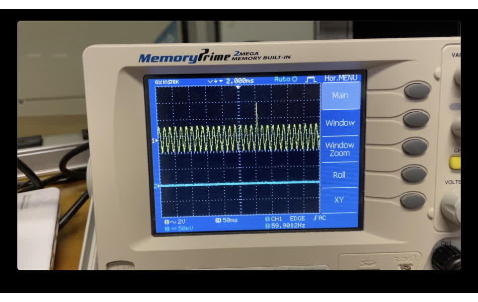
As our group assignment, Justin and I characterized our freshly made board using an oscilloscope (another machine with a non-user-friendly interface). We probed the clock pin, and the oscilloscope read out a frequency of ~60 Hz. We also pressed the button and observed a jump in voltage.
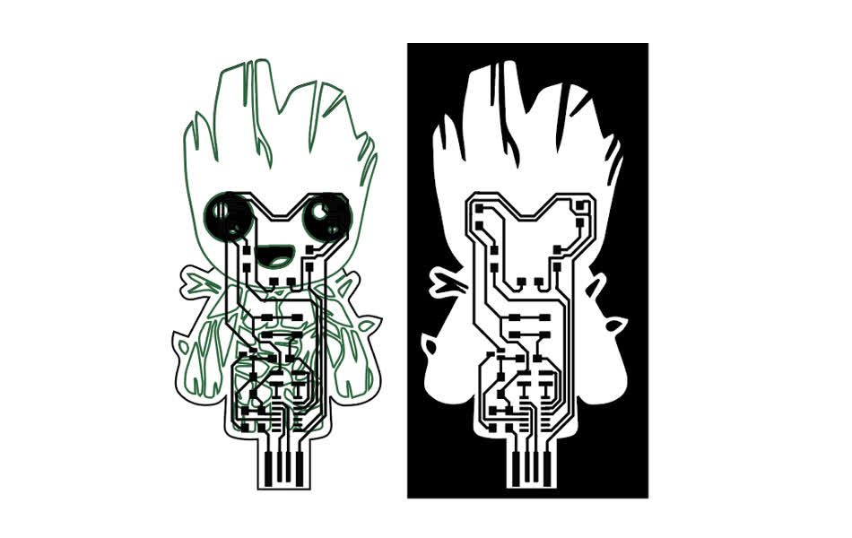
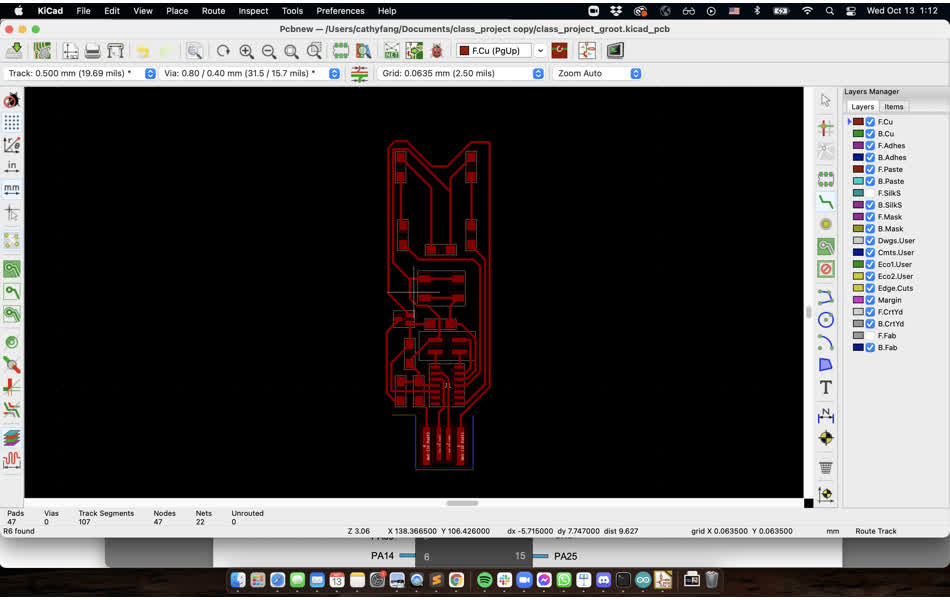
I ran out of time to finish my creative take so here is just an illustrator file of my design. I really like Groot from Guardians of the Galaxy, so I want to make my MCU ;) in a group shape. I modified my old schematic to add another LED and resistor and connected it to another pinout on the MCU. Then I manuvered around the footprint such that the LEDs become the eyes of baby groot and the rest is the body.
For proof of concept, I found this sketch of groot online and used illustrator to image trace the outline. My plan is to cut out the PCB as usual but make a transparent acrylic case and cover with the same outline, and then use the vinyl cutter to add the design on top of the acrylic cover. Here is a preview of the output. For now, please imagine that baby groot's eyes would be lit up.