October 13, 2021 | V. Electronics Design
The electronic design of my microcontroller circuit board took longer than expected. There were many issues to troubleshoot, and it was a lengthy learning curve for me. Of our two options KICAD and Eagle ECAD situated in Fusion 360, I chose Fusion 360 to design my echo hello-world board. I have a paid subscription to Fusion 360. It is an investment made from the onset of this class. However, from my experience, it is the most complicated of the two software proposed.
My first encounter with trouble in Fusion 360 was the FAB Libraries. In my schematic design, I used the UC_ATSAMD21E18A-AUT found in the FAB library. However, the version included within the fab library downloaded did neither match the version included within the tutorial nor meet the "fab.drc" clearance. On account of this, I experienced complications during milling my initial echo hello-world board. In addition, the traces on my board were too thin, and my PNG had too much negative space around the board's traces and outline. The combination produced a tiny echo hello-world board with skinny traces on a blotched copper board. Thus, I had to start from scratch to revise my errors (well, not entirely from scratch).


I deleted my PCB document in Fusion 360 and created a new one to link my design's schematics. Then, I rerouted my components on my board. I made sure to include more space between traces. I decreased the negative space around my board's traces and outline and checked for clearance. My micro-controller: UC_ATSAMD21E18A-AUT, still did not meet clearance. I brought the issue to my TA, and he was able to resize it within Fusion 360.


Following my many failed attempts in Fusion 360, I milled my PCB board. Surprisingly Mods and the milling machine were not the complicated part. Although the process is long, the terminal, mods, and Roland were straightforward. Once your file is in good shape, the settings are correct, and the proper process is followed, the results are consistent.
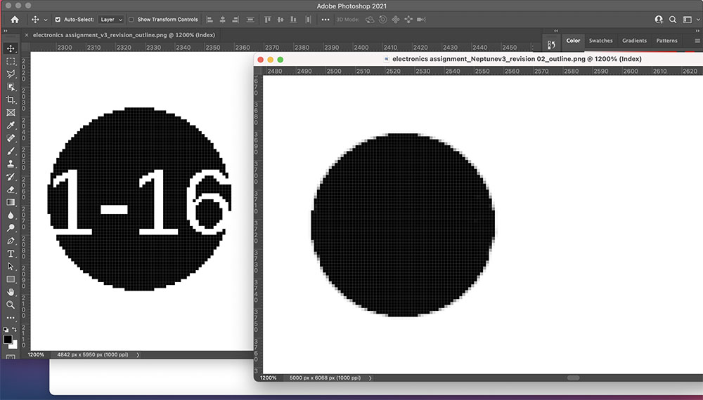
Once my "echo hello-world board" was printed, I noticed my "Vias" were not drilled. Instead, my "Vias" were exported with numbers displayed in the middle. The milling machine did not register my board's drill and gave them copper circles instead. To remove the numbers shown in my "Vias" I was advised to import my .PNG's into photoshop and manually remove them. As the video did not explain this issue and my knowledge in electronics design is limited, my process was delayed further.


Mods will register the drills only after removing the numbers manually via photoshop from both the trace and outline. Although I did not complete the process, I now know the process and limits of designing an echo hello-world board in Fusion 360. I learned that having the right component and footprints within your library is critical. In addition, I learned the importance of establishing space within your design (spacing your components and traces out and checking for clearance). Finally, I realized that Fusion does not remove numerical symbols in "Vias." Is there a command in Fusion that does this? I am not sure. Although I can't imagine Fusion, a very sophisticated software not having that capability, I will continue to use photoshop until I find a resolve.

Update (11/10/21): The Vias within my board's design was problematic. As I have limited experience with electronic design and embedded programming, I decided to eliminate my vias and route all GNDs. Next, I redesigned my board and adjusted it to include a component from this week's lesson on input: sensors and signals. Finally, I milled and soldered my components to my PCB board. At certain sections, it was found that signaling within my GND was not reaching all parts of the board after testing. Jumpers were placed on my board to resolve the issue. The image below features my board without an input sensor.


I wanted to echo my board before including the sensor to accomplish this assignment. Therefore, I attempted to upload a bootloader to my board and echo it. I tried using EDBG, and it's an alternative OpenOCD on my Mac's os system. However, I encountered issues with both processes. In EDBG, my computer found an error in finding the directory: /usr/local/libhidapi.dylib after changing the make file. In Open OCD, I encountered difficulty in installing the gdb-Multiarch due to issues with java script. I will attempt this again using another alternative and TA assistance to complete this assignment.


---------------
File Links:
Fusion File: htmaaschematicdesignfile.fschEagle Compatible File: htmaaschematicdesignfileeagle.sch
Fusion PCB 3D Graphic: htmaaschematicdesign3dgraphics.stl
Traces: electronicsassignmentneptunev3revision02tracescopy.png
Outline: electronicsassignmentneptunev3revision02outlinecopy.png
New Trace: htmaainputsensorandsignals_Traces110721.png
New Outline: htmaainputsensorandsignals_outline110721.png