Making a conductive Bio-Ink Printer (Attempted)
This project didn't end up working in it's entire form. It's a relatively simple project for some but for me, I tried to figure out how a lot of the mechanical components worked just using pictures and I have never built a machine. Considering that I failed at the first thing I decided to do in this whole class, I tried to reflect back on where I went wrong
1) As someone with a similar background to the one taught in class - I got too excited by trying to all the sensors/actuators and controllers. A good thing to be enthusiastic about but it also meant that I nearly did the entirety of my final project in one week ~ 5 days. This was a really bad idea because I had a lot of personal reasons why I could only work late nights on those 5 nights → Translated to me not sleeping for 7 days for more than a couple of hours.
2) I also ended up not asking for help when I needed it because I thought my questions were stupid. Sometimes it just helps to double check your circuits/system with the TA
If I could go back in time, I would start this project early Int he semeste.r And start thinking at a systems level about how I would built various components.
Making Cyanobacteria ink is an involved process that itself will take a couple of weeks. So Decided to just built a machine that can mp4e in three axes that later can be a conductive ink printer.
1) Introduction
2) BOM
3) Laser Cutting Parts
4) 3D printed parts
5) Putting it all together
6) Circuit Design
7) Making the frame
8) Thoughts
1) Introduction
My inital plan was to make a bio ink printer. But I ended up changing it to making a conductive ink printer because making bio ink would have been too much for the short time in this class. While I have a background in electronics - I have never built a complete machine before so I was mildly overwhelmed. I really should hav finished my circuits before embarking on the mechanical portion
I originally wanted to make a conductive ink printer.I made the motors and thought I would use the CNC Plotter from here - https://www.instructables.com/Easy-3D-Printable-Arduino-CNC-Drawing-Machine-Low-/ as my basis for XY axis and then have a simple ink extruder to be a conductive ink printer. I made the 3D prints using the link here. But after we discussed Core XY machine during machine week - I have a week to make a XY axis + Z-axis. And I am so bad at mechanical engineering anything. I didn't realize how much I suck at mechanical parts of the design. I spent about 15 hours on 3D printing all the parts I needed for this over the semester.But since I changed my mind after the machine week - I now had to build a CoreXY system in one week.
It seems a lot smoother and because both the motors are in one place at the end - the electronics will be easy - I hope - will find out at the very end since I don't plan to actually do the electronics till the last minute. (UPDATE- This was a disaster because I didn't finish my circuits in time)
Laser Cutting
I made the XY axis on the laser cut with a 1/4 inch acrylic. I need two sheets - two 12x24 inches long for the axis. I got one black and one acrylic because those were the sizes I could find at Altec Plastics.
After my initial attempt at cutting and nothin being the right size I went and cut everything on cardboard first. Also, acrylic is so expensive - I wish I did the whole thing on cardboard. The DXF files used were from the original CoreXYimplementation. I did want to try the more minimal system that everyone seems to be using with just the corners but → I wanted a more closed dish system and a plate I can lift off - so I can let the cells incubate in the chamber that is completely sealed.
I noticed that the entire project - original version from CoreXY was purely done using a laser cutter - there seems to be a distaste for 3D printing. For example the bushings etc attached to the acrylic for making the rails seemed like something I could easily 3D print. After speaking to David, he mentioned that 1) 3D printing wasn't ubiquitous back then + 2) Epoxing a bushing actually gives a little more wiggle room if I make any tiny mistakes in my laser cutting etc.
Before I cut anything on acrylic, I made a frame out of cardboard - It was a good idea - because the files in the CoreXY implementation seem to be out of date and the screw sizes don't fit as they should. So I made a few updates to this (You can see this below in my files section).
Instead of using aluminum for the main frame (I don't know how to use the water jet), - I used 1/4 inch acrylic. Acrylic is expensive!
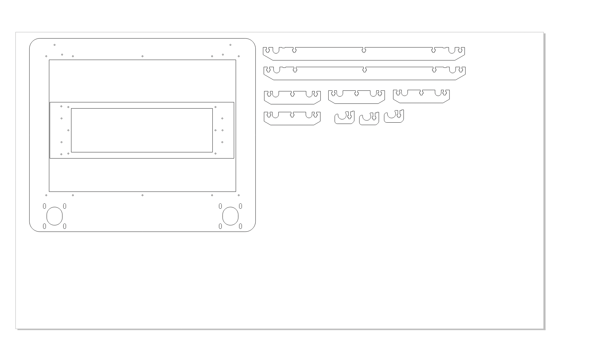
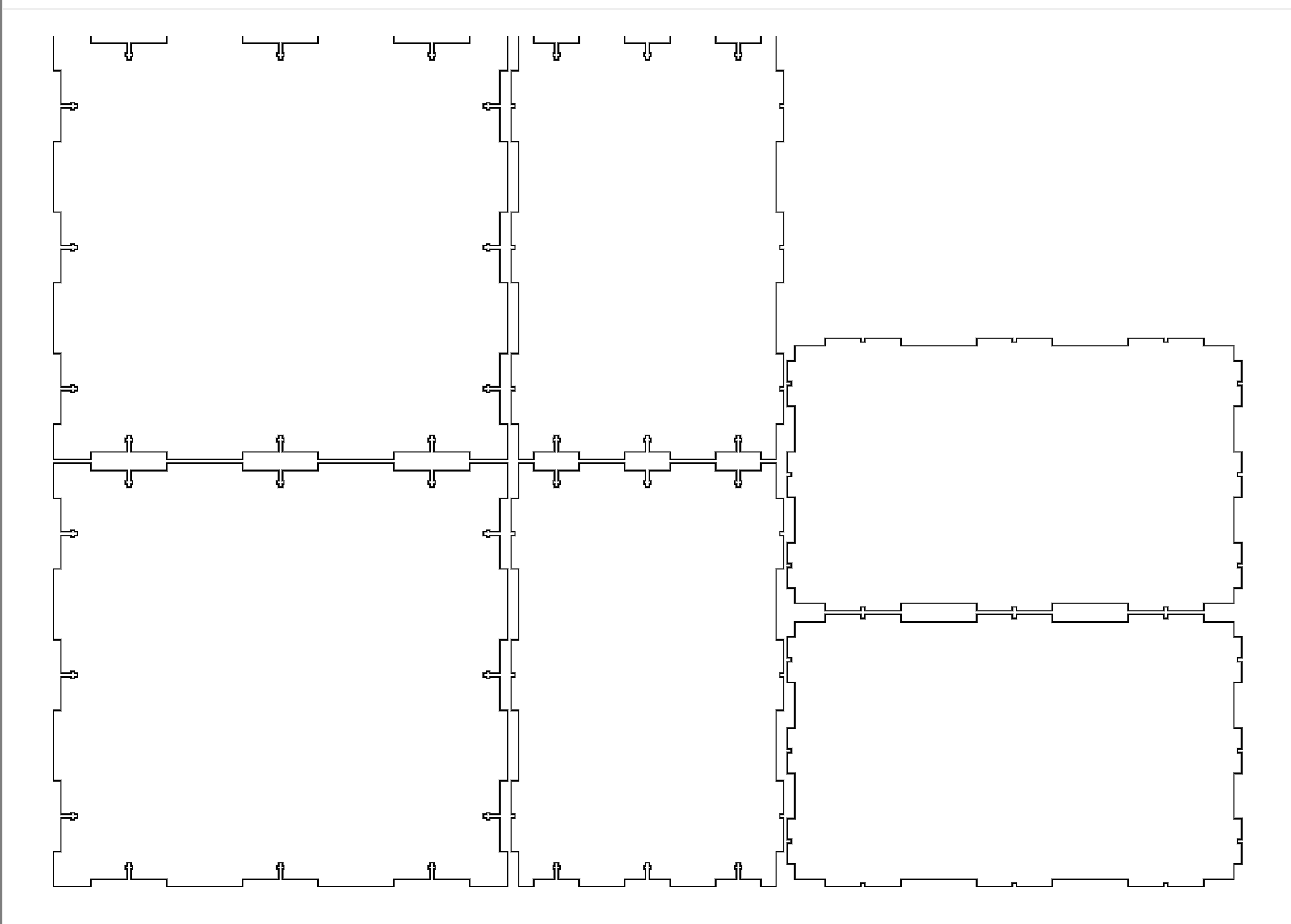
I am going to laser cut my frame out of acrylic - I don't plan to have a super long axis. I don't want a long axis because conductive ink doesn't do well on large traces from my understanding. and I don't think my print head would be too large so I am going to use acrylic.
Here is the design of my laser cut acrylic for the main frame. Notice, that I just utilized the wasted piece inside the first one to cut both out . This also ensured that the plates fit nicely with each other.
I used 0.7 speed 200 and PPI 400.
I finally cut all my pieces and now it's time to assemble. this took way too. long than it should. I kept realizing that I didn't have the right screws. And also since I didn't use the aluminum and used a 1/4 inch acrylic instead. The width of the plate and the screw sizes on the CoreXY site didn't match so I had to go to Home Depot (three different ones) to find M3x20mm.

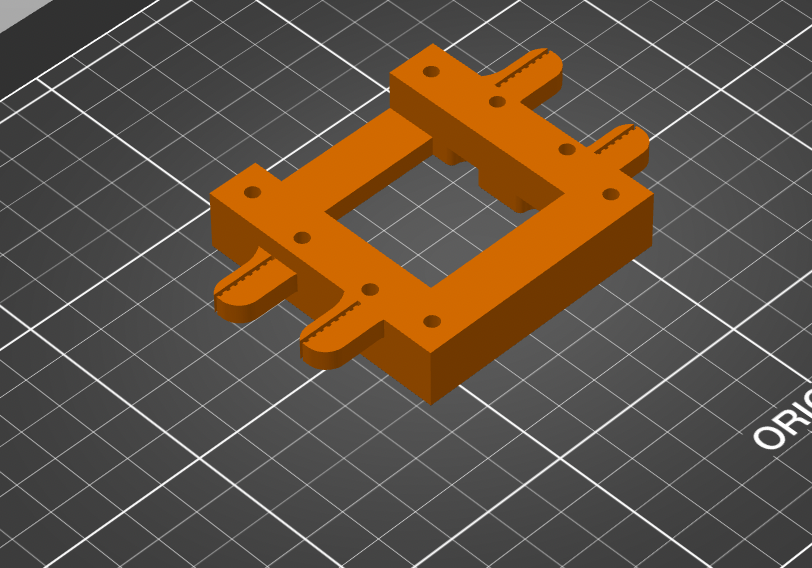
3D Printed
While I was laser cutting, I went and 3d printed the frame that is going to mp4e along the railings and be the base for my print head. In the CoreXY implementation, the model is laser cut in layers and then glued together. Which I don't need to do since I have access to so many 3d printers. So I combined all the. layers and made one print head.
Assembling everything!
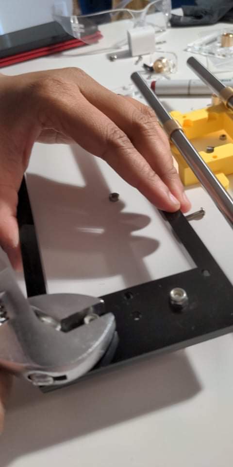
The hardest part of assembling was the gluing of the bushings to the acrylic and the pla. I first started with the X-axis. and used the rods in the bushings. I then applied a tiny bit of epoxy on the surface and placed the bushings and held it in place for 5 min. This is the epoxy used - https://www.amazon.com/3M-Scotch-Weld-Epoxy-Adhesive-DP100/dp/B0074N8HS8
This was tricky because the epoxy seems to mildly expand and has accidentally gotten into one of the rods of my railing. So I had to replace - it was glued on pretty tight. Luckily I had an extra metal rod.
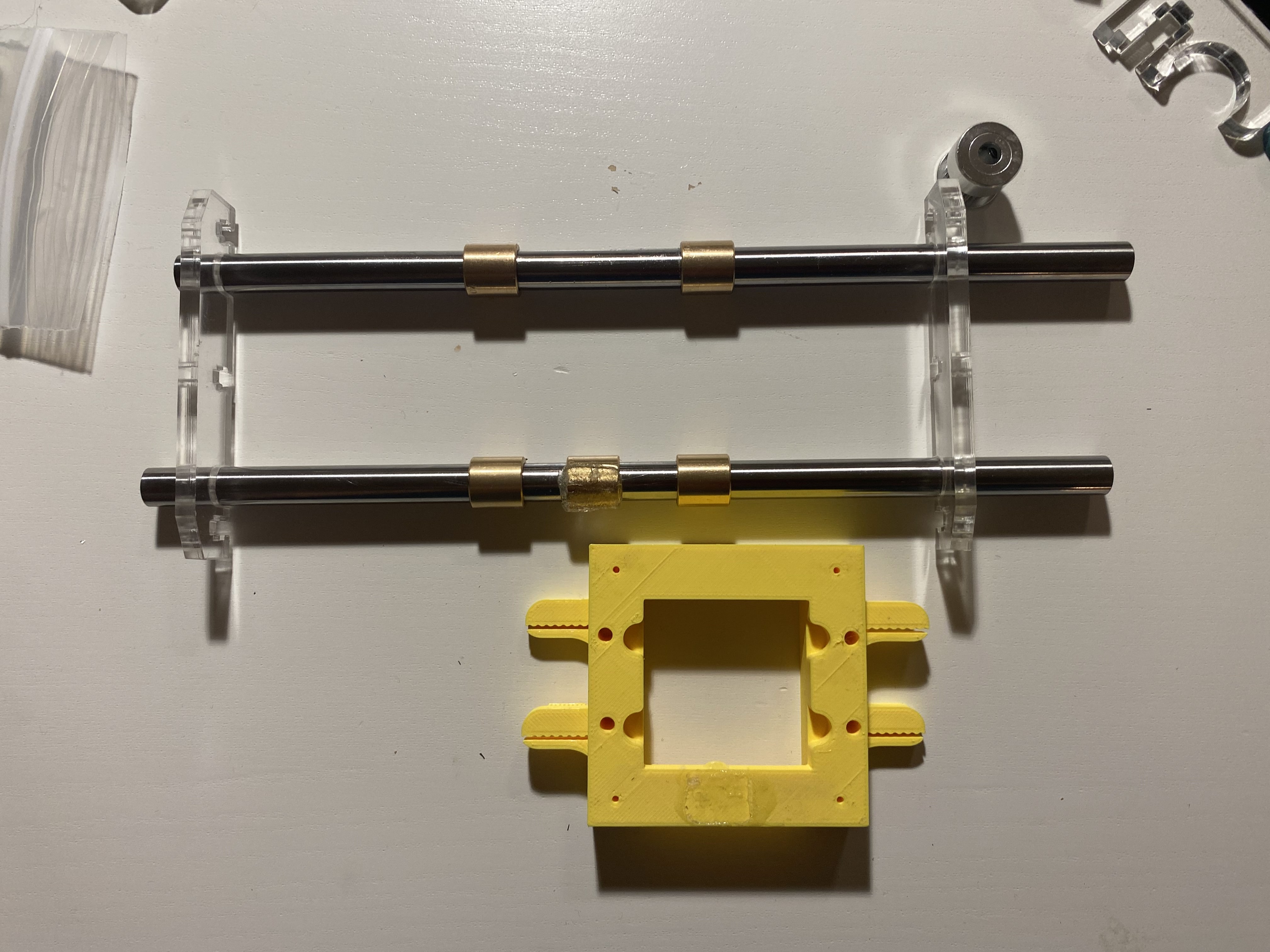
I tested it manually as you can see above - It was still very tight - I added some olive oil but it does take some force to get it to mp4e. This became an issue when it came time to add railings and mp4e it with the motor because the belt wouldn't stay put because of the amount force being exerted on it.
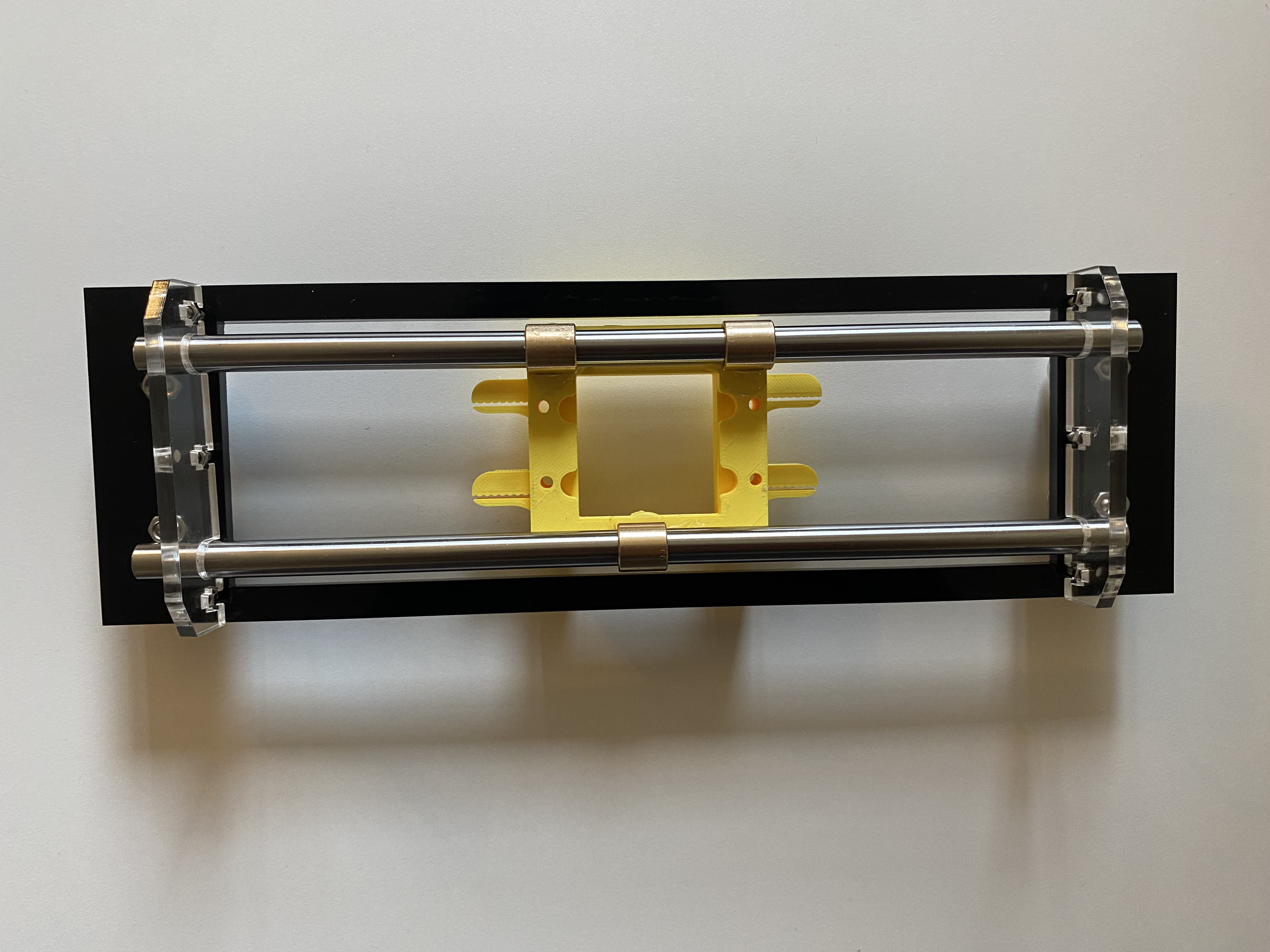
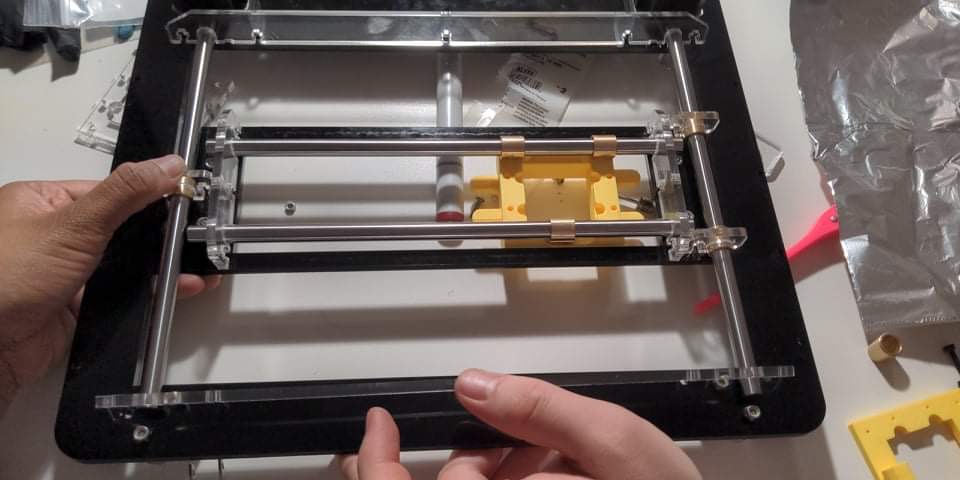
Next I assembled this x-axis on to the y-axis acrylic bits. This was a two person job. It looks like this
2/12/2021
Rushed ordered some BOM from McMaster. I ordered more than I needed because I am pretty sure I will mess up something and I didn't want to panic at the last minute
BOM
| 1 | 94150A325 | 316 Stainless Steel Hex Nut, Super-Corrosion-Resistant, M3 x 0.5 mm Thread, Packs of 50 | 1Pack | 1 1 | Column |
|---|---|---|---|---|---|
| 2 | 92095A181 | Button Head Hex Drive Screw, Passivated 18-8 Stainless Steel, M3 x 0.50 mm Thread, 8mm Long, Packs of 100 | 1Pack | 1 | |
| 3 | 1679K686 | Dust-Free Timing Belt, MXL Series, 1/4" Width, Trade No. 770mxl025 | 2Each | 2 | |
| 4 | 6381K451 | Multipurpose 660 Leaded Bronze Sleeve Bearing for 3/8" Shaft Diameter and 1/2" Housing ID, 1/2" Long | 12Each | 12 | |
| 5 | 6061K108 | Linear Motion Shaft, 1566 Carbon Steel, 3/8" Diameter, 10" Long | 4Each | 4 | |
| 6 | 6061K22 | Linear Motion Shaft, 1566 Carbon Steel, 3/8" Diameter, 9" Long | 4Each | 4 | |
| 7 | 92095A183 | Button Head Hex Drive Screw, Passivated 18-8 Stainless Steel, M3 x 0.50 mm Thread, 12mm Long, Packs of 100 | 1Pack | 1 |
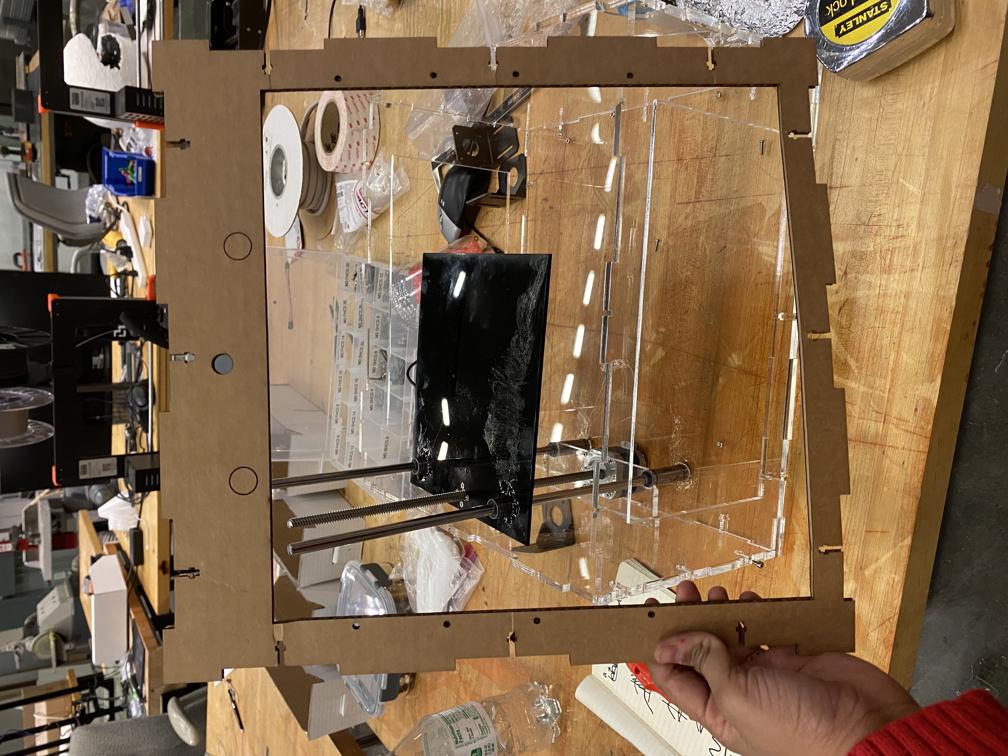
Putting it all together
I started with making a rail for the x- axis first. This was a two person job and I had to ask my partner to help. First I put a tiny bit on epoxy down and then places the two part bushing rail down. Next I repeated the same thing on the other side. It's important to make sure you only use a small amount of epoxy other wise you will end up with accidental epoxy in your railing and that will. make a mess. Luckily I ordered extra rods because the bushing on got very very stuck and I was worried I might have to re do the whole project
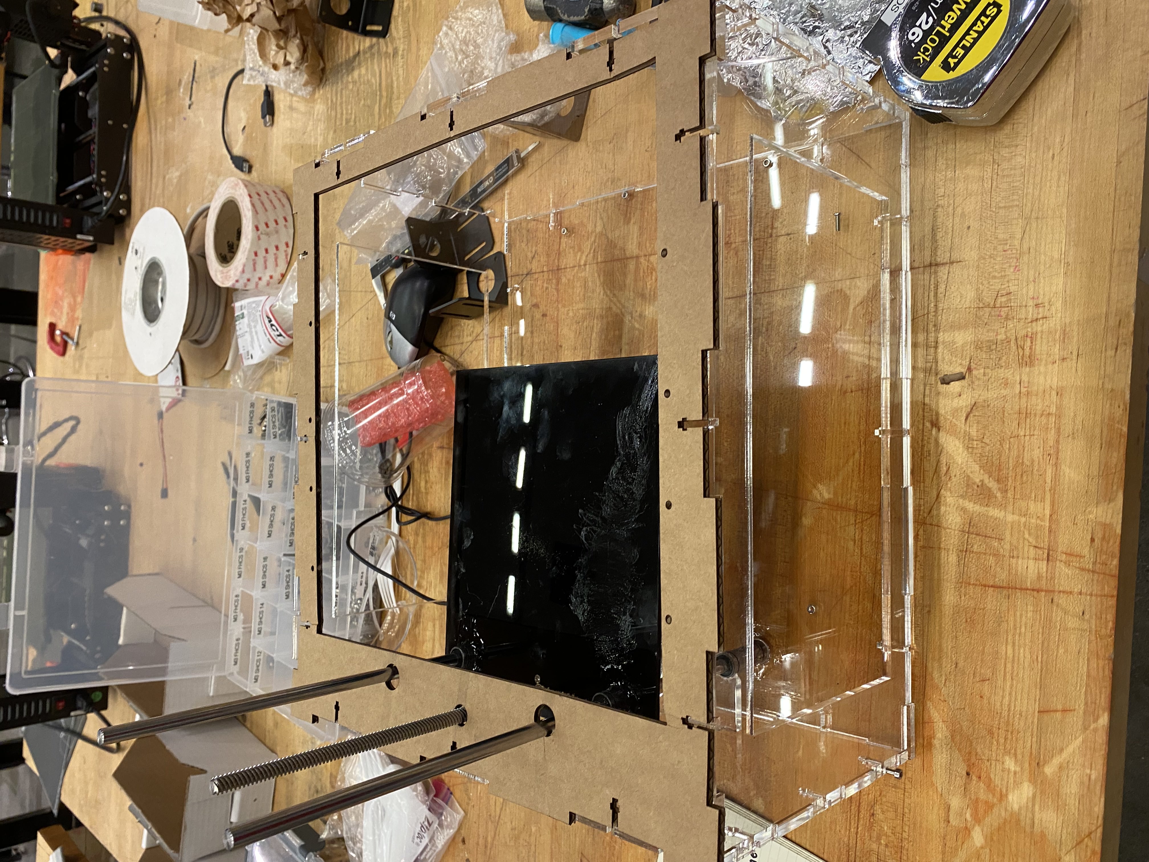
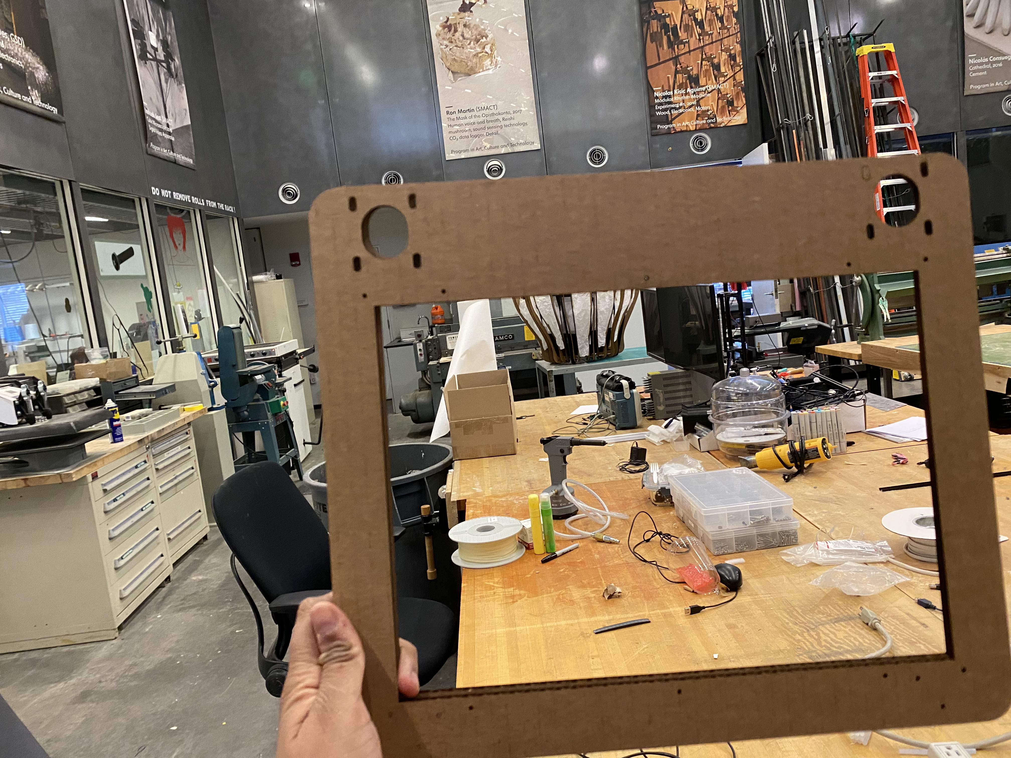
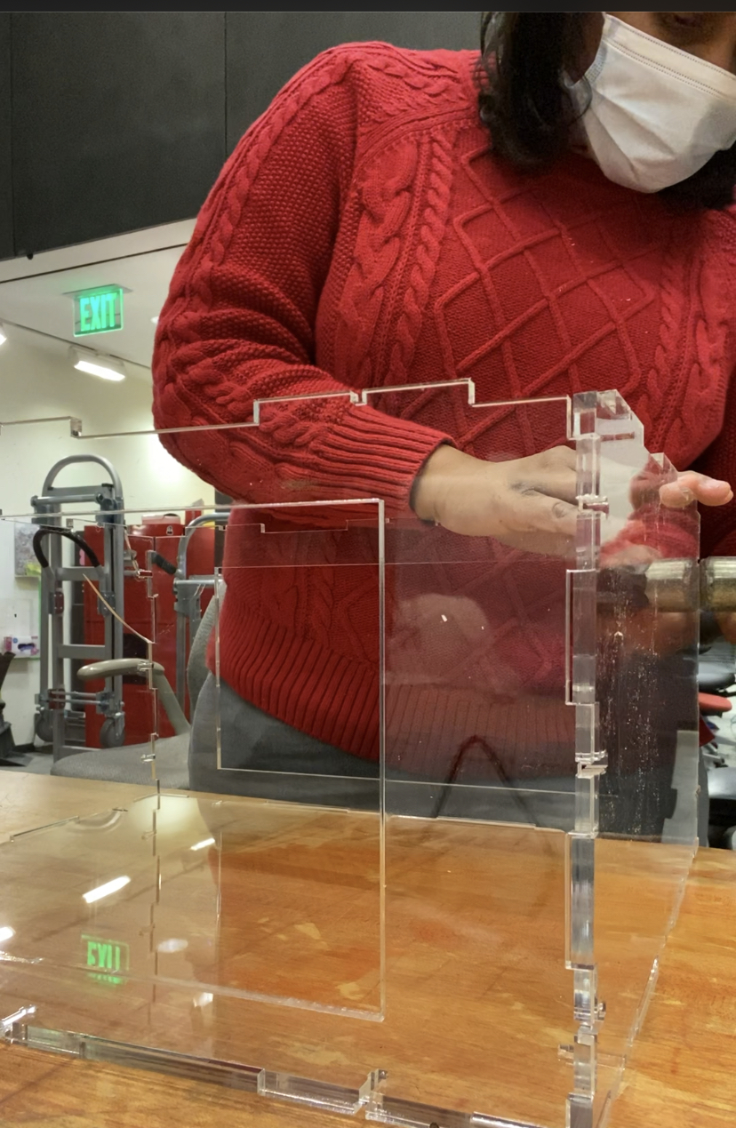
Making the frame
I want this to be a bio ink printer. I want the XY axis to be taken off and sealed when it's done printing. So the box can also function as a incubator for the bacteria.
I used Makerspace to make the starting pieces for laser cutting
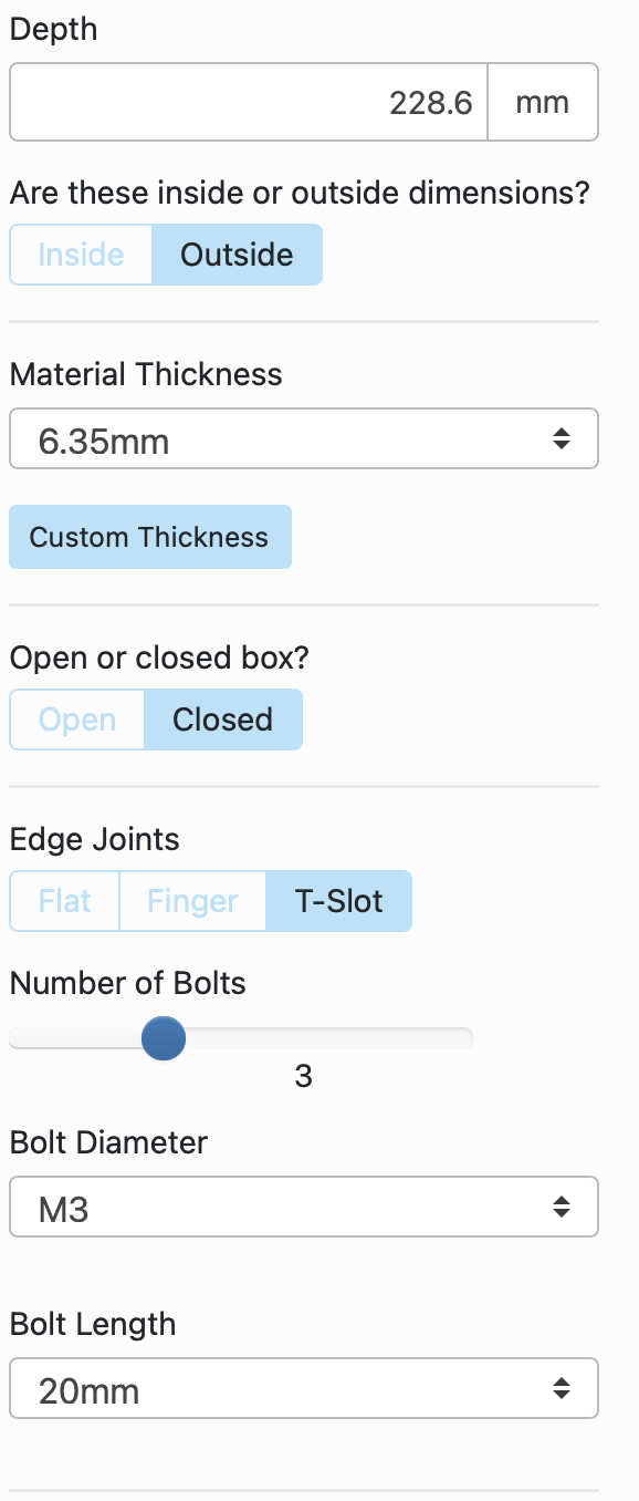
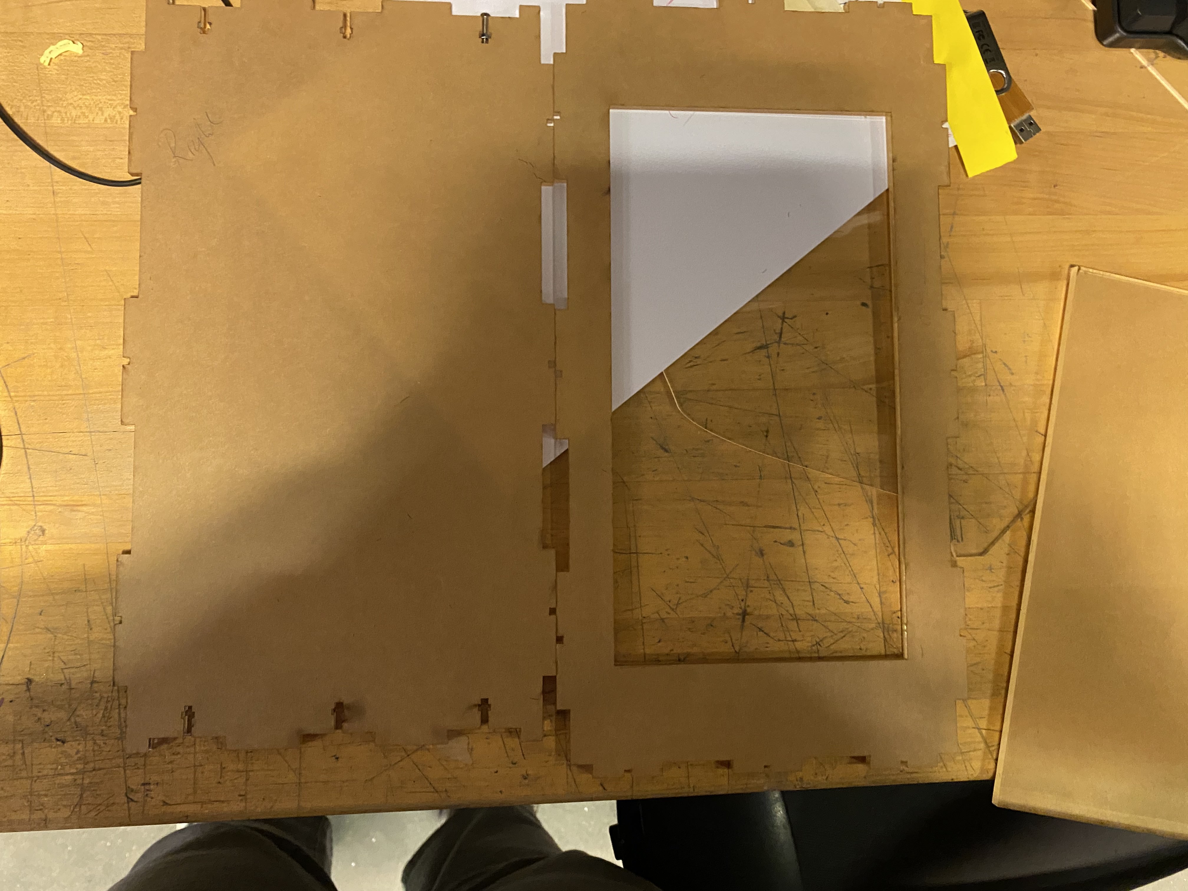
I then cut square holes on the side pieces so I can have access inside the box. In the next version I plan to have a door I can tightly seal with magnets maybe. The top was tricky. MY plan was to have a hole that can just hold the XY motion plate in place but I didn't make the box big enough (I was constrained by how much acrylic I had left). You can see this in the first few pictures above. I had to hammer the pieces down before screwing in the m3 screws. The kerf for acrylic I measured was 0.15mm so I adjusted the designs accordingly in CorelDraw
Electronics
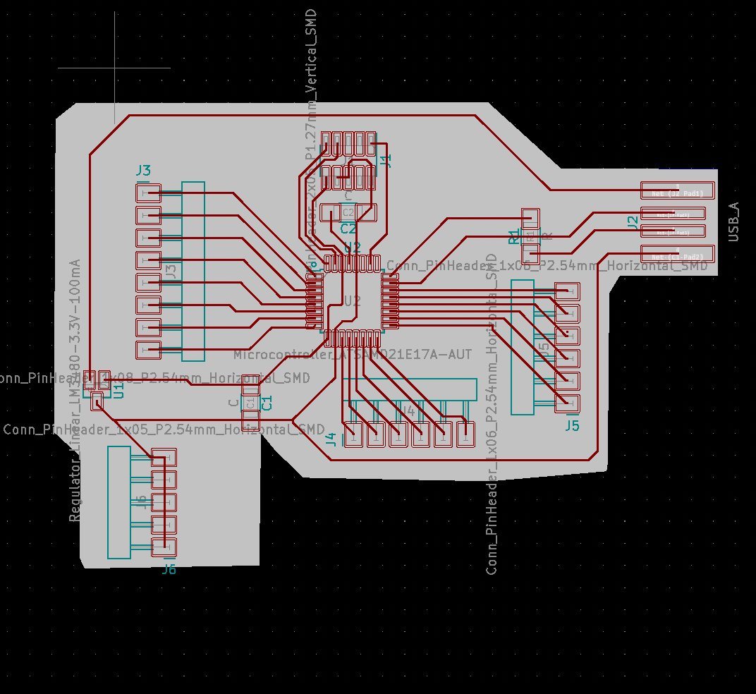
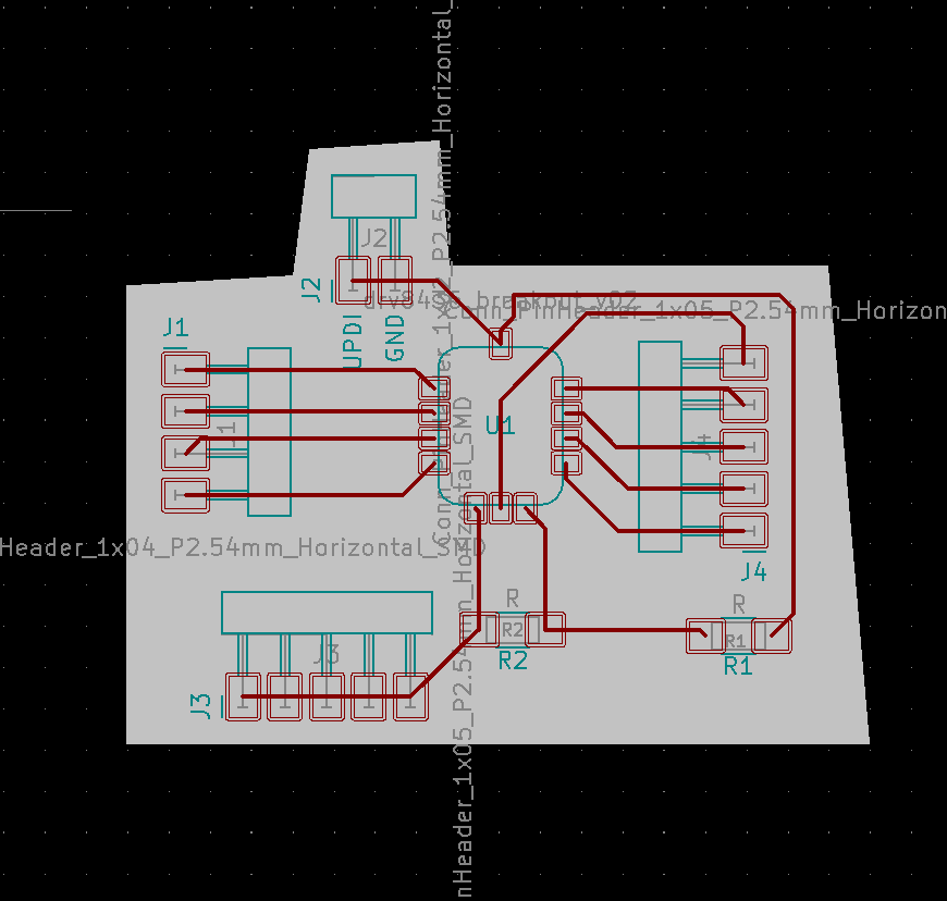
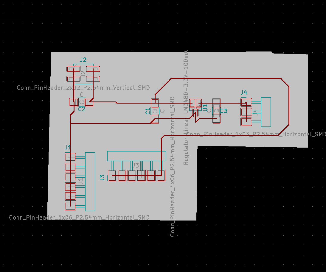
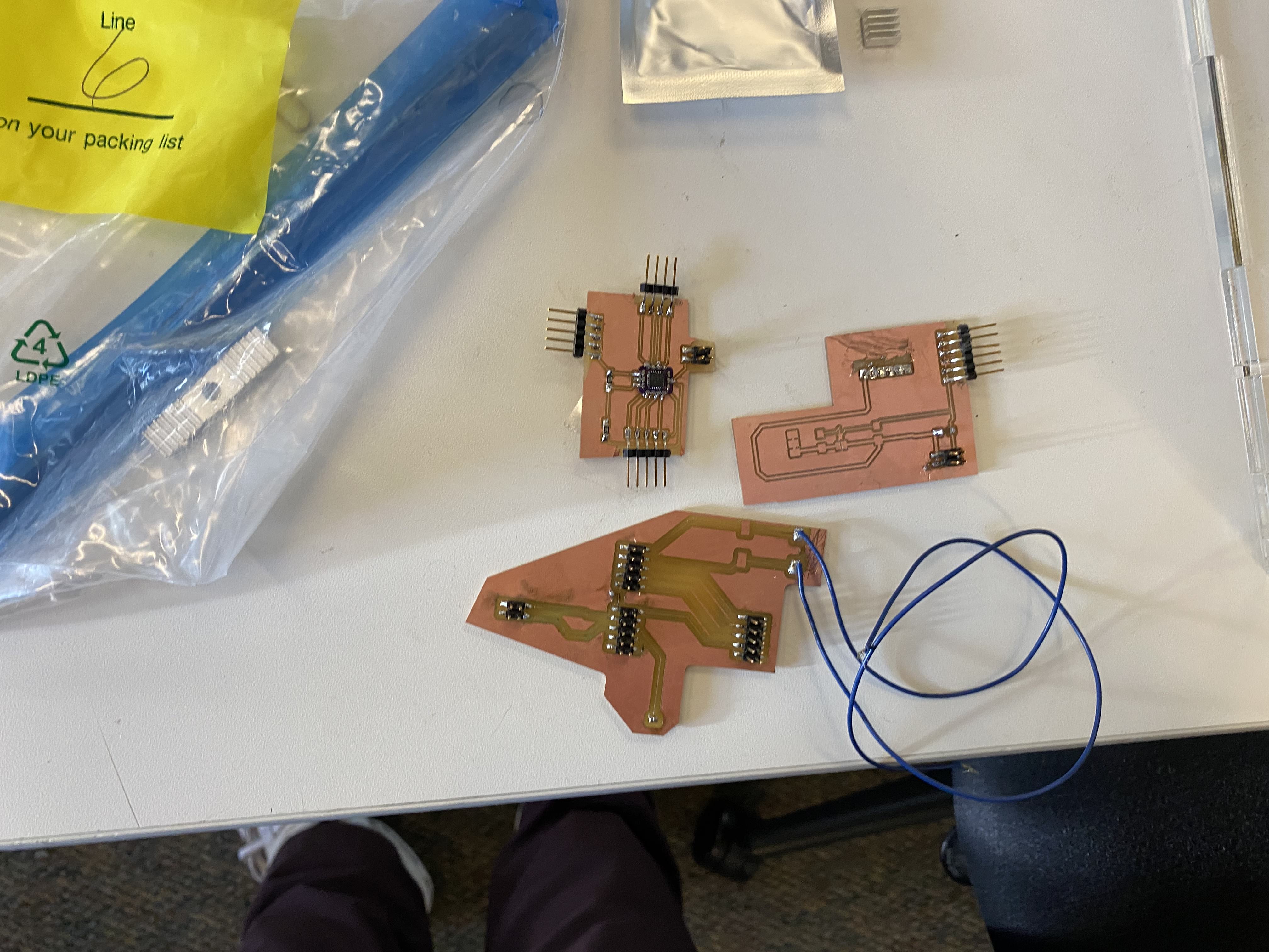
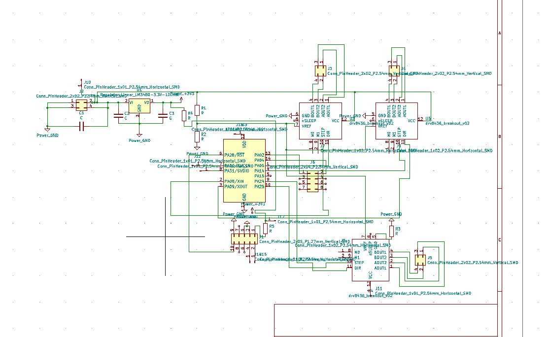
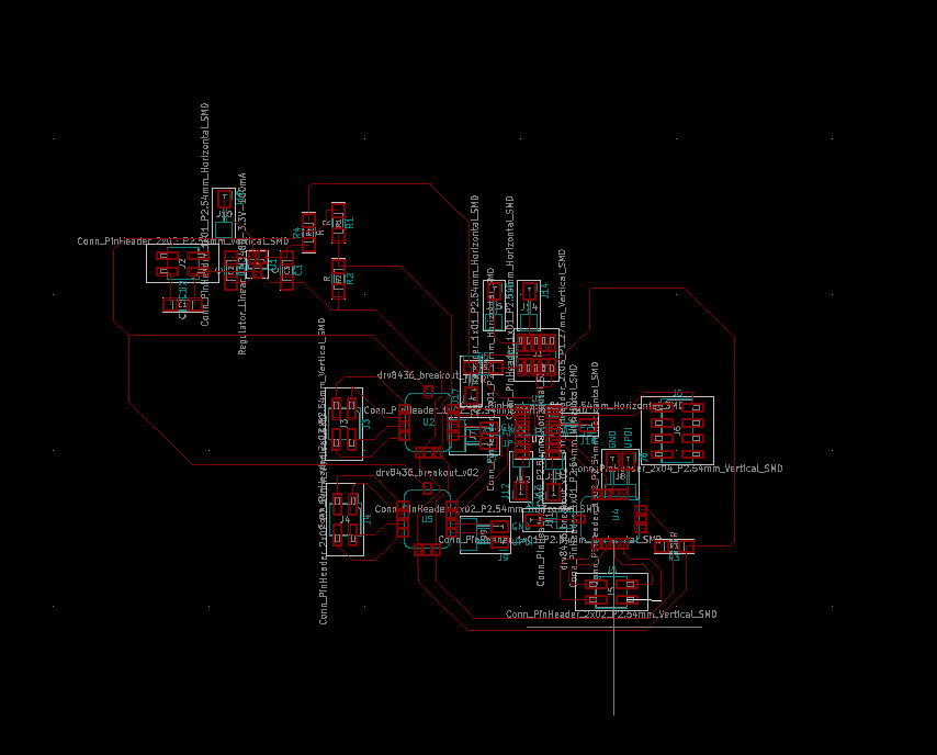
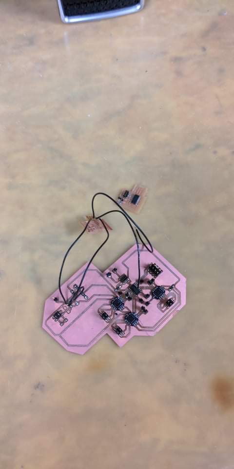
I made a circuit with DRV8825 DRV8436 and A4988 with SAMD11/21/ESP 32 in this class. Refer to my electronics production week for the circuit with SAMD11. You can also find the circuit design I made for the DRV8436 - SAMD11 below. My initial plan was to use a drv8825 for xy axis with SAMD11 and use ESP32 z-axis with the A4988 because those are the drivers I have. But I lose my drv8825 driver board somewhere between week 5 and last week so I had to make new ones with DRV8436 ones that Zach made. I probably should have taken pictures but it was pretty late at night and my leg was too tired to go get my phones charger so here are the boards I could take a picture of.
I find SAMD21 hard and long to mill with no guaranteed results. I wish there was a one shot way to do this. I tried everything from trying to lie about the mill diameter or the trace width changes or dpi etc. Every time its something new. At this point I am happy to deal with ESP32 issues.
But I did start with SAMD21 at the beginning of final project week and after struggling to get the board taped down to the block during milling I finally made three boards - one voltage divider circuit/one driver board and one SAMD21 controller. After 2 hours of milling the board SAMD21 - trace came off. I tried to make jumpers between them and just made a mess. I did send the board to a PCB fab so hopefully it won't have the same issues. Will report back when it comes back.
To make connections across three dimensions easier - I thought it would be best to split into circuits - voltage divider/motor driver with drv8436/SAMD21 controller
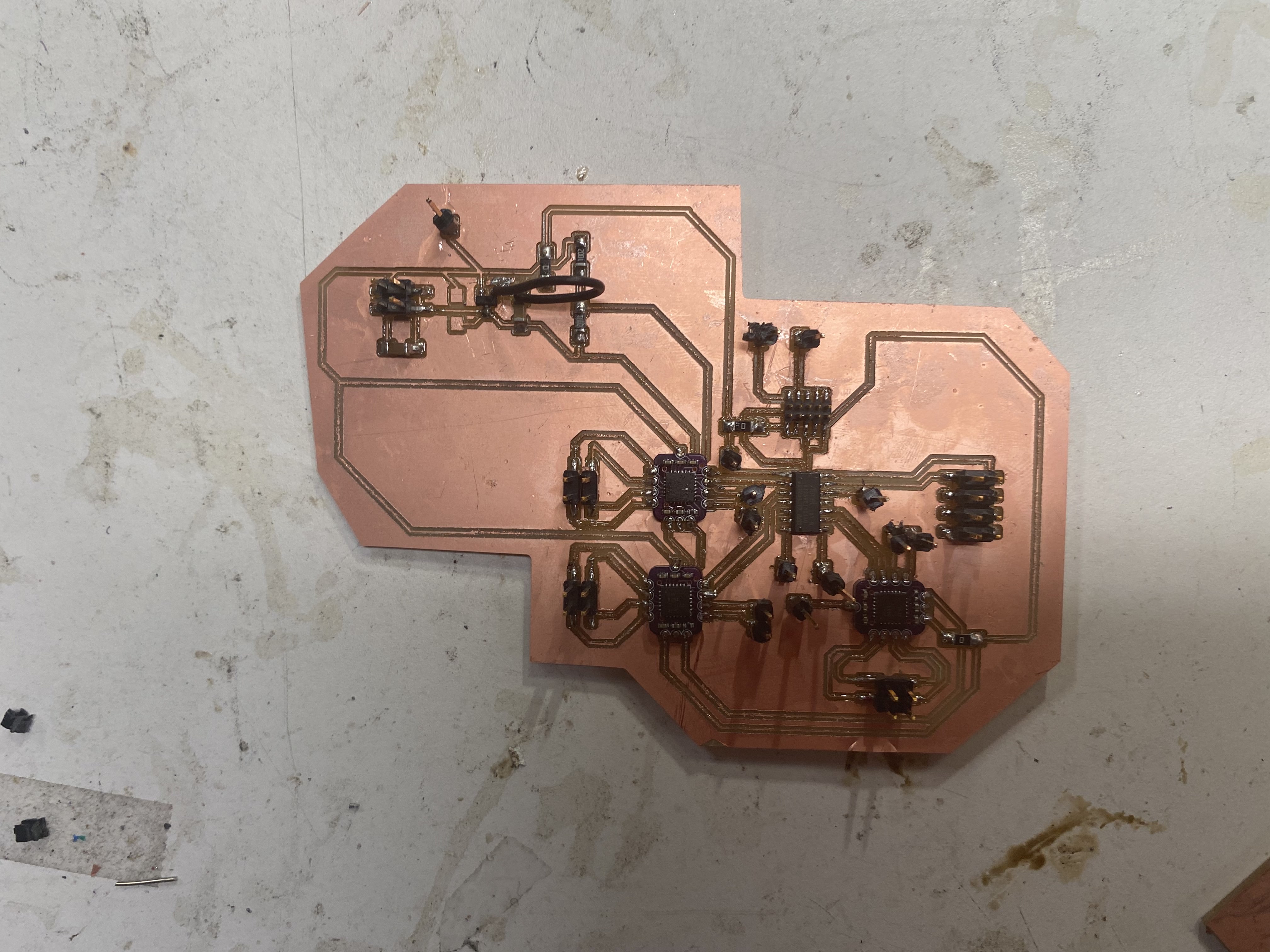
SAMD21 milling is way too hard - and is difficult with the 1/64 end mill . I redid the whole circuit for three motors in SAMD17
After this I didn't really feel like re-milling SAMD21 again so I decided to do a 3 motor board with SAMD17.
I thought it would be enough to set the voltage from the voltage divider and it didn't register that I did need a USB port while running the edbg binary. So I had to some surgical editing later
Still didn't work - I tested with the multimeter all the expected voltages etc but still the driver weren't getting the right voltage on the pins. I figured I might have damaged the drivers because I used the heat gun to extract them from the previous boards since the cba shop didn't have anymore of them.
One Motor on SAMD17


Three motors on a SAMD17 (sacrificing M0/M1 microsteo select pins)


So I sadly had to go back to using ESP32. I hate using ESp32. I like the idea of having one clean board for everything and using esp32 seems like admitting defeat and dealing with a pretty unclear programming things. This semester I tried to do interrupts.I2c and etc with ESP32 and none of it was a pleasant experience.
But I had two A4988 I ordered and two I found in the desk of electronic components in my office. ESP32 had so many pins so I used a breakout bard to make common VMOT and GND and then hooked up all the motors.
And all it does it make this terrible sound when hooked up
That's pretty unpleasant - It mp4es slightly. But it is nowhere enough to be a pen plotter of any kind. I am not sure if it's my power - I tried to adjust the potentiometer on A4988 and it just stopped working after the second try.
I tried to do one motor at a time . When I was doing the z-axis - I realized the lead screw is the problem . If I unscrewed it a little bit it worked fine like below. I know it's the screw because the motor works fine on it's own. So I am not even sure where to start debugging the z-axis.
I tried the same approach- same STEP/DIR pin and same the driver and same VMOT and GND on all three motors and interestingly only one worked. Only one of the A4988 boards was working! Only one. I think the issue was my drivers! I bought them and found them in bins and never bothered to check them. I am pretty the drivers are the issue because I tried every combination possible to try and debug things. I used the one A4988 and the me pins and tested that all the motors work individually on their own. I really should have tested all three at once before but since one worked I was pretty laid back about it. Lesson learnt. Here is one motor trying it's best to do the job all on its own.
I ordered some new drivers. They will get here this Friday so I am hoping to retest my circuit. Will update back when it's working.
Thoughts
I am pretty disappointed that it didn't work completely. Part of the reason is me changing my design last minute and part of the reason is me not estimating how long circuit design takes. I will continue to work on this in the next weeks.