Week 3 - Electronics Production
For this class, we learnt how to use the Roland SRM 20 Milling Machine to make our own PCB's. And then we stuffed the board with components.
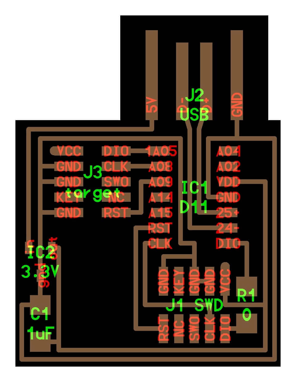
I chose to make a JTAG programmer for this week. I obtained the traces that I need to cut from here - http://academy.cba.mit.edu/classes/embedded_programming/SWD/hello.CMSIS-DAP.10.D11C.jpg
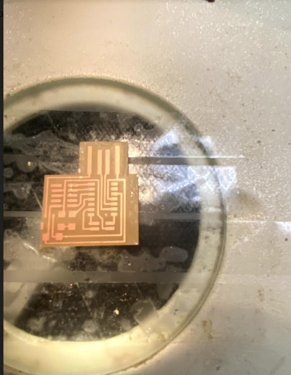
I cut the PCB on the milling machine after two failures because I didn't make sure the board was lying flat. Here is a failed attempt
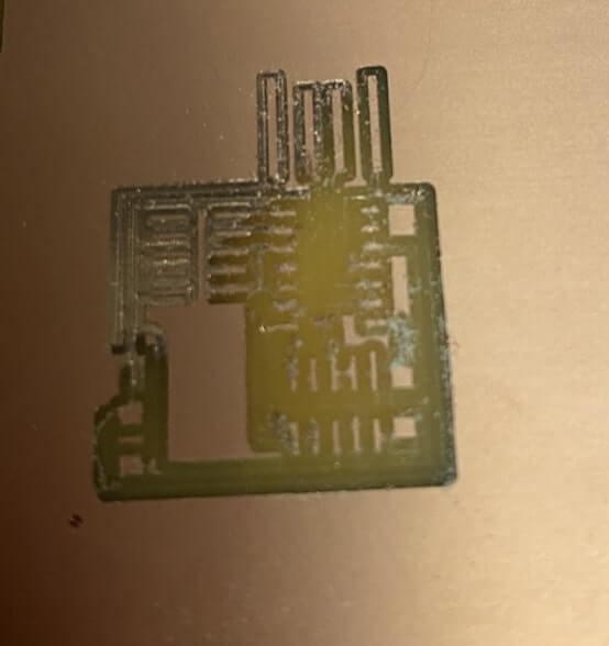
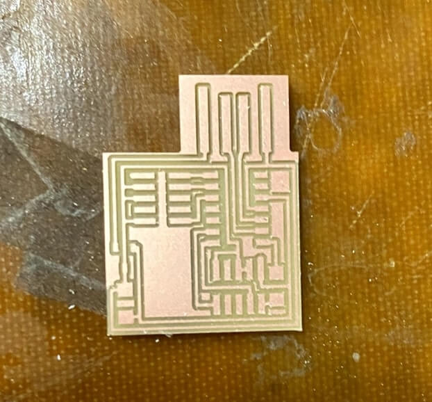
I removed both the sacrificial board and the board I am cutting and re-taped it down flat this time.And it worked this time.
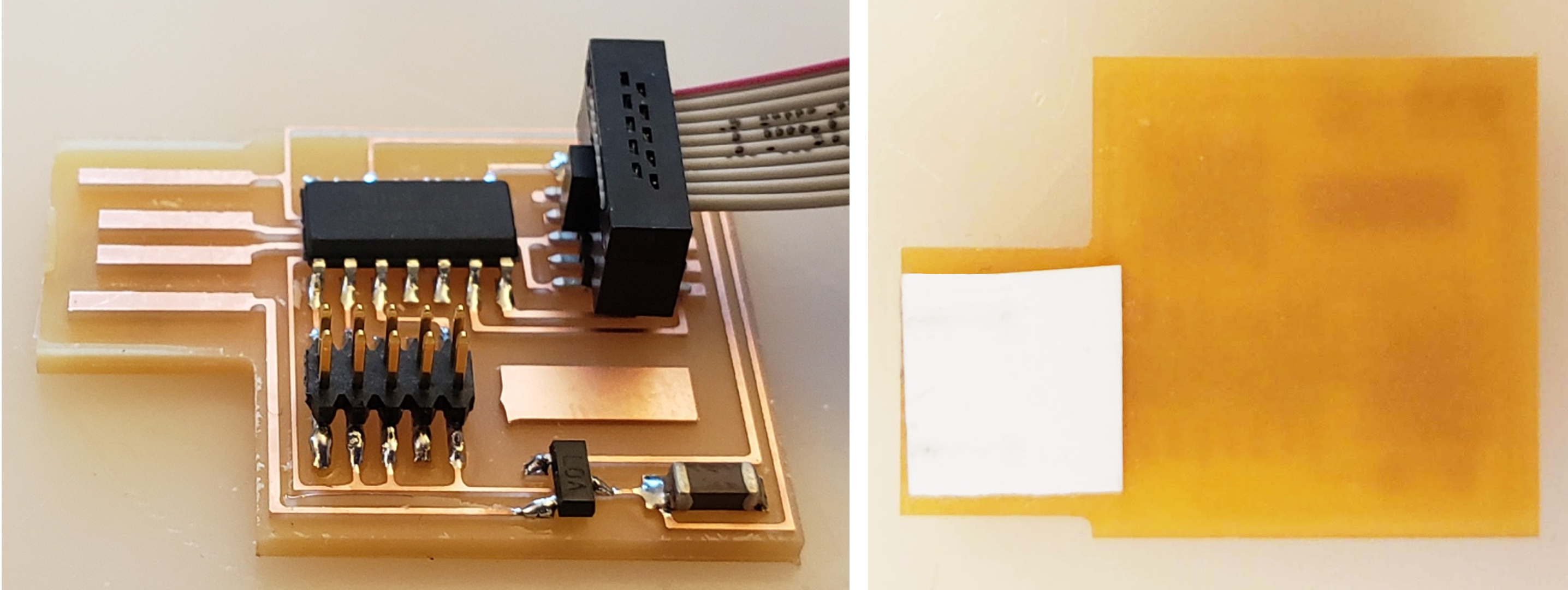
Once I got the board I wanted, I gathered all the components I needed. I got the components I needed from the board picture above. The Resistors and Capacitors I found easily. And IC was straight forward. The voltage regulator was a 3.3v voltage regulator. And I looked up the data sheet of the SAMD11C to find the right orientation of the pin based on the dot on the IC.
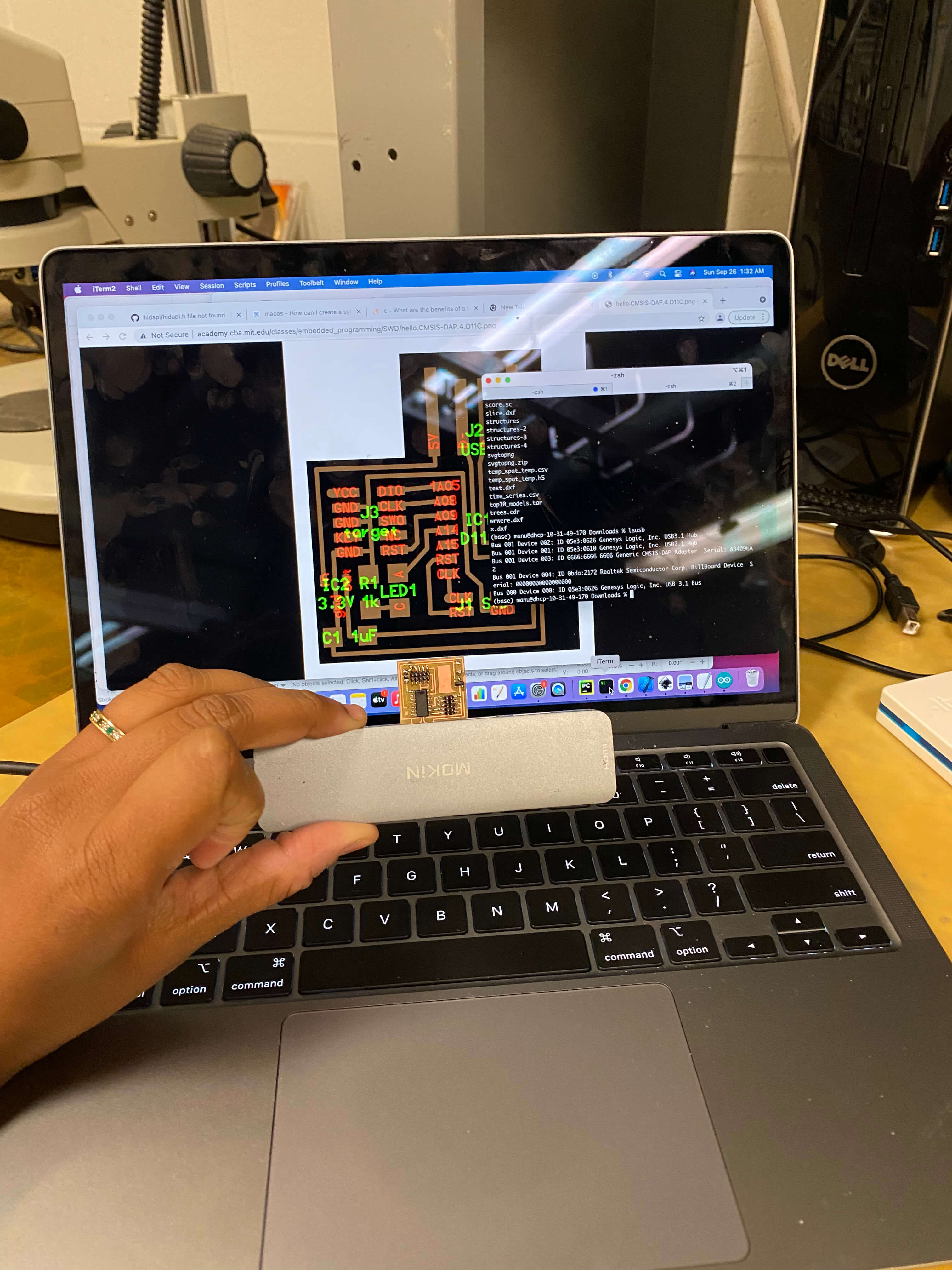
I have really bad eyesight and I have not soldered SMD components a lot before but I soldered a ton of through the hole component boards so I knew how to solder. But my hands are not the steadiest and my eye sight is not that great. So I taped my board down on the microscope plate and used the base of the microscope to keep my hands steady.
Soldering Tips:
- Flux.Flux.Flux - I used generous amount flux on my pads
- To solder my resistors and capacitors I first heated the pad with solder and flowed some solder on it and then with tweezers in one hand and the solder in the other hand, I easily slid the resistor into place. Same for the capacitor
- To solder my microcontroller IC. I first placed the IC on the pins it was supposed to go on. I then heated a bit of solder onto my solder iron and passed it onto one of the pins of the top left of the IC. I then dabbed a lot of flux on the other pads. Next, I soldered the bottom right pin. I kept soldering it pin by pin by alternating on each side.
- The tricky one was the 3.3V IC voltage reg- For that I found it easier to solder a pad and slide on of the two pins onto it
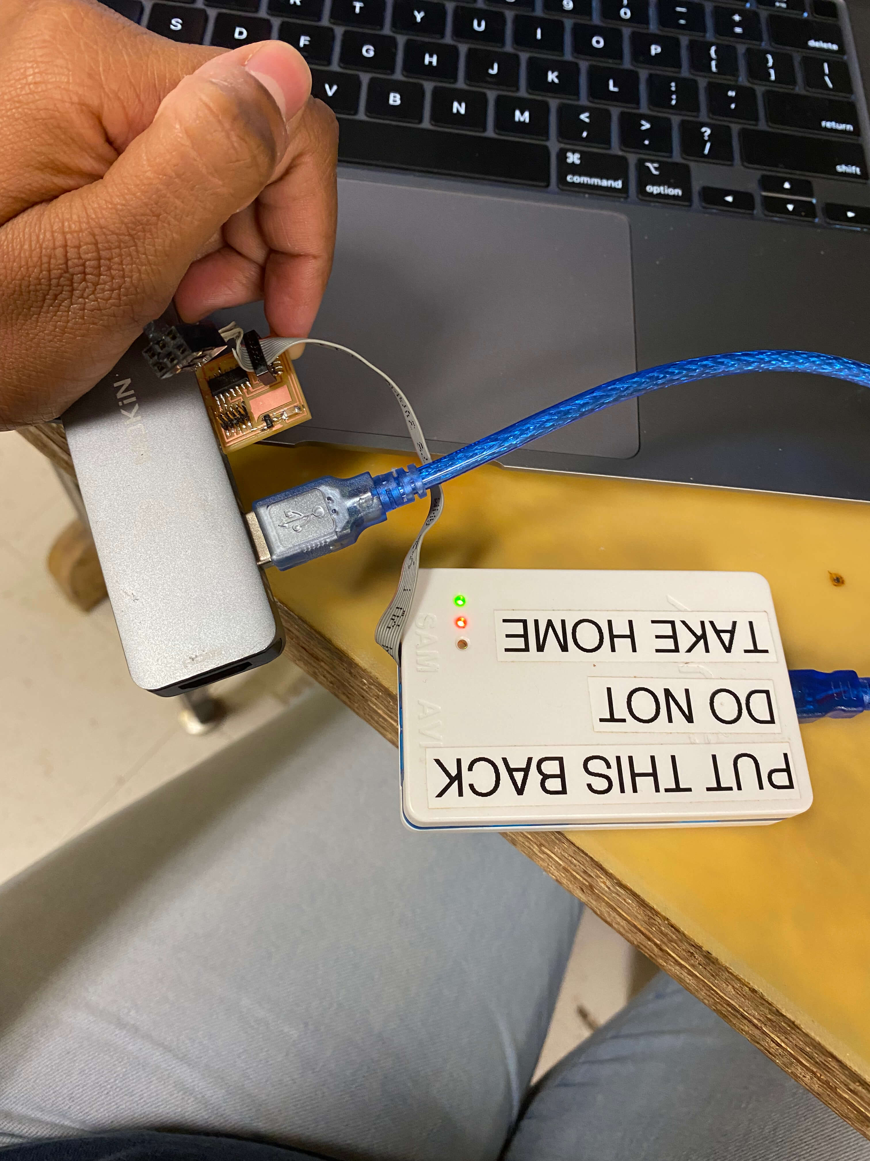
After populating my board time to check if it's going to work. To program my board, I first needed a programmer. For this I used an existing programmer in the lab that looked like this. Too me a while to figure out I also needed to plug the usb part in along with the serial cable.
I setup edbg - I downloaded it from here - https://github.com/ataradov/edbg . The setup instructions are straightforward. I had to install hidapi via brew on my Mac. After that just run make all in the edbg folder. And make sure to add the edbg folder to your path!
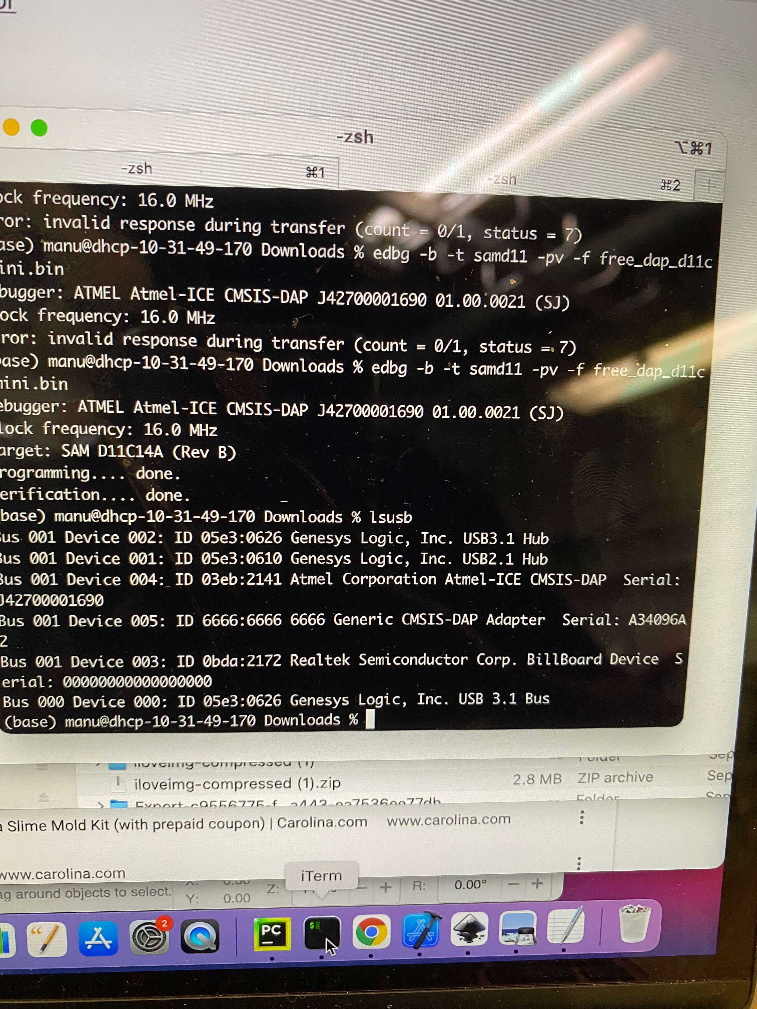
if you did lsusb on your Mac terminal after you plugged everything in - > You will see one of the adapters shown. That is the pre-existing programmer (the white case).
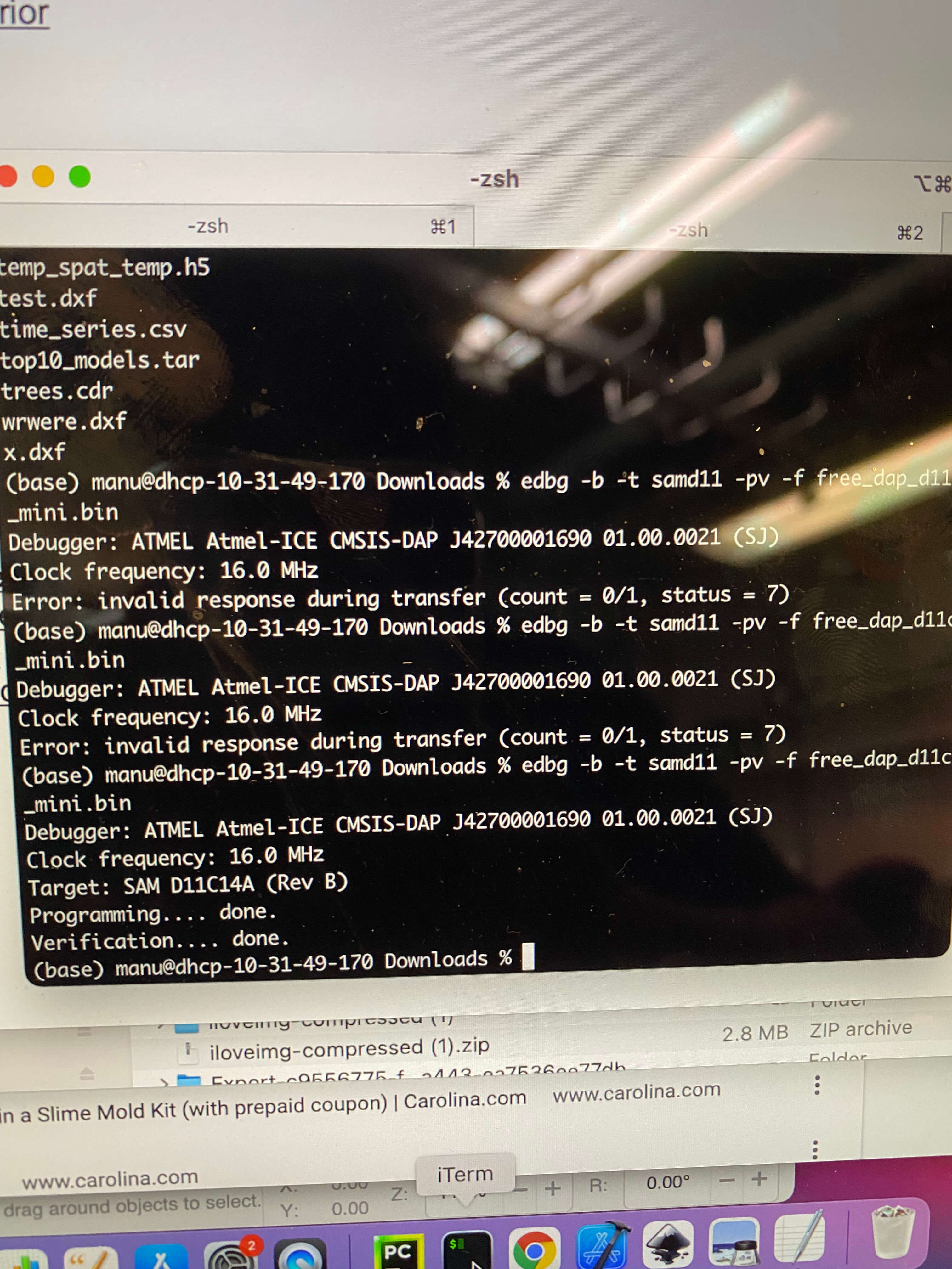
I downloaded the binary for making my PCB also a CMSIS-DAP adapter from - the site here - http://academy.cba.mit.edu/classes/embedded_programming/SWD/free_dap_d11c_mini.bin
And I ran the command in the picture here on the left.
it successfully programmed it on the first attempt!
When I ran the command - initially I got some invalid errors because my usb connection wasn't great. SO I had to hold it in place - maybe I should have soldered those connections a bit - which I did do later on
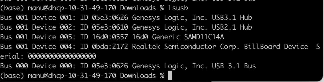
Now if you ran lsusb you will see two of these show up
I then disconnected it from my screen to see if it would recognize the plugged in usb device and it is recognized!
If I ran system_profiler on Mac I get
Atmel-ICE CMSIS-DAP (This is the remade one I am using):
          Product ID: 0x2141
          Vendor ID: 0x03eb  (Atmel Corporation)
          Version: 1.01
          Serial Number: J42700001690
          Speed: Up to 480 Mb/s
          Manufacturer: Atmel Corp.
          Location ID: 0x01140000 / 4
          Current Available (mA): 500
          Current Required (mA): 100
          Extra Operating Current (mA): 0

        Generic CMSIS-DAP Adapter (Mine - Alex Taradov is the author of edbg utility I used to program):

          Product ID: 0x6666
          Vendor ID: 0x6666
          Version: 1.00
          Serial Number: A34096A2
          Speed: Up to 12 Mb/s
          Manufacturer: Alex Taradov
          Location ID: 0x01120000 / 5
          Current Available (mA): 500
          Current Required (mA): 400
          Extra Operating Current (mA): 0
Yay! now I can recognize my device as a debugger!
I wanted to also load a boot loader on my pcb so, I attached it back to the programmer. Bootloader is a program to load programs on to my PCB. I downloaded the boot loader .bin from here - https://github.com/mattairtech/ArduinoCore-samd/blob/master/bootloaders/zero/binaries/sam_ba_Generic_D11C14A_SAMD11C14A.bin
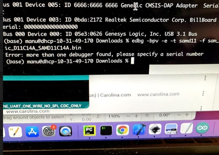
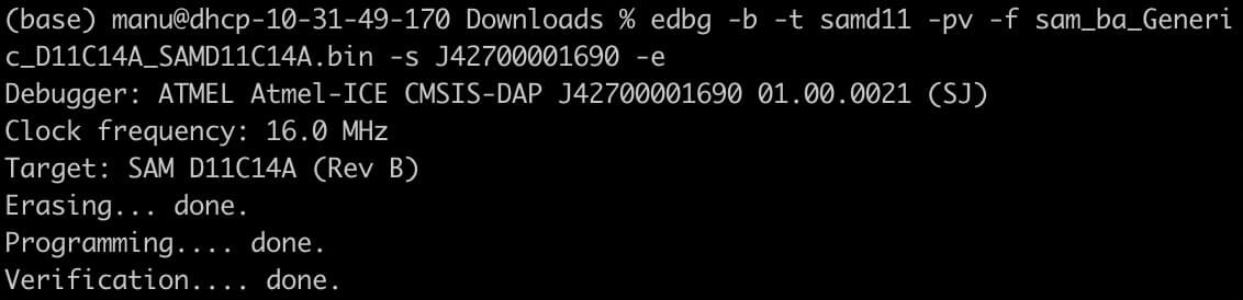
And I ran the edbg command - Except now I have two debuggers!! So I went ahead and selected the right programmer serial number.
Next, I was able to successfully load the bootloader program
Note, because - I had the earlier program in my PCB already. If I did lsusb after flashing the boot loader without -e it won't show me my PCB in the usb devices. So make sure to use that -e . -e erases the earlier contents.
Now, I can just connect my PCB via the USB port and my computer recognizes the device! It's ready to be programmed! Sadly, I don't have any fun input & output devices to play with, for now I reverted it back to being a debugger.
Next, I found the milling machine quite fun. And realized that I can also make a construction kit that's milled using the same joints etc we laser cut in the last week. So I decided to make a 3D PCB. I made a very simple PCB layout - One LED and One Resistor - 499 Ohms and one battery. To make the components - I didn't want to do the whole KiCAD /FlatCAM so I used fusion 360 and CorelDraw.
1) First, I took Neil's trace into coreldraw and did an outline trace. I was able to find the trace width and pad dimensions I needed this way.
2) I went back to Fusion 360 and made the circuit designs I wanted
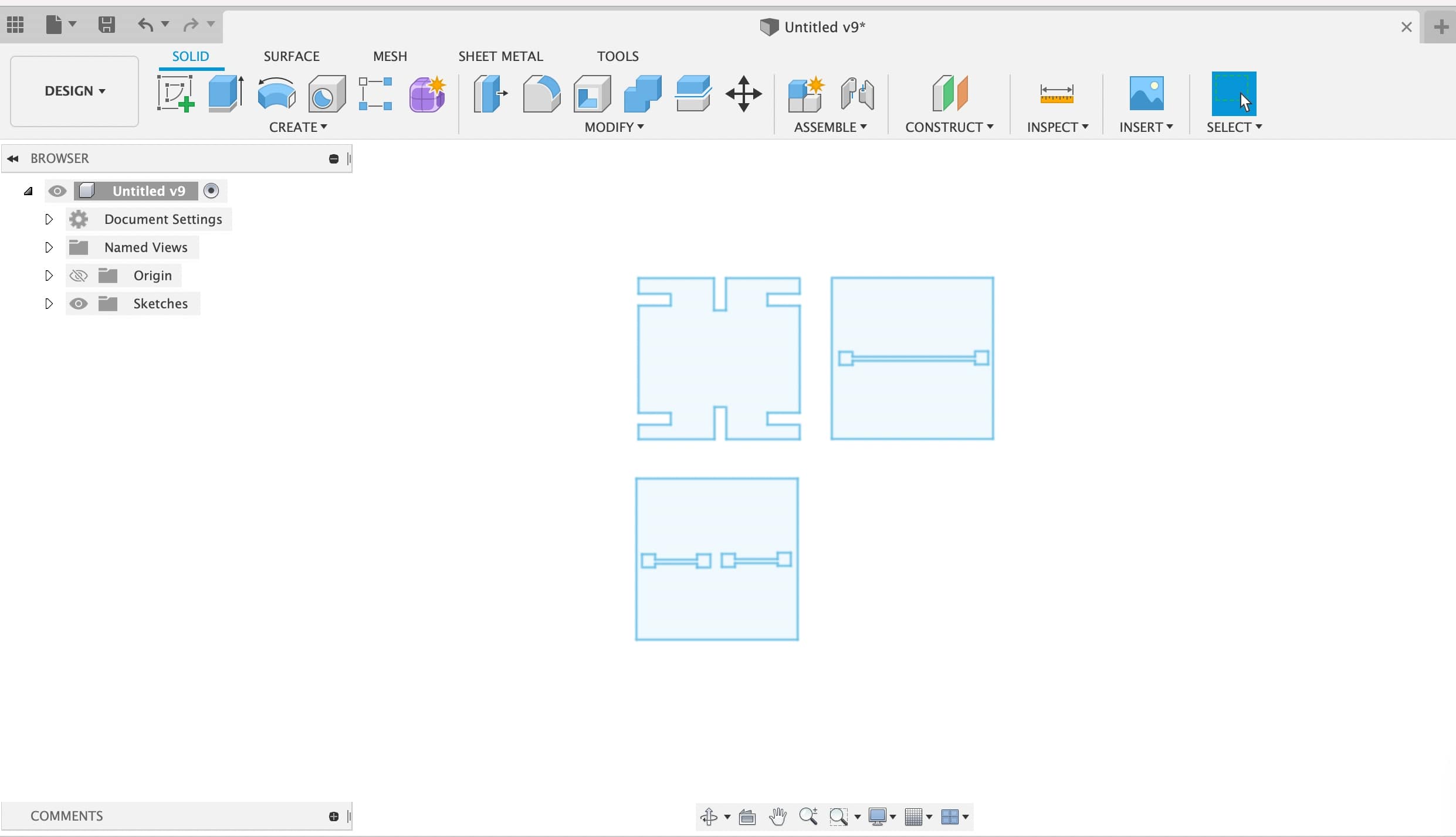
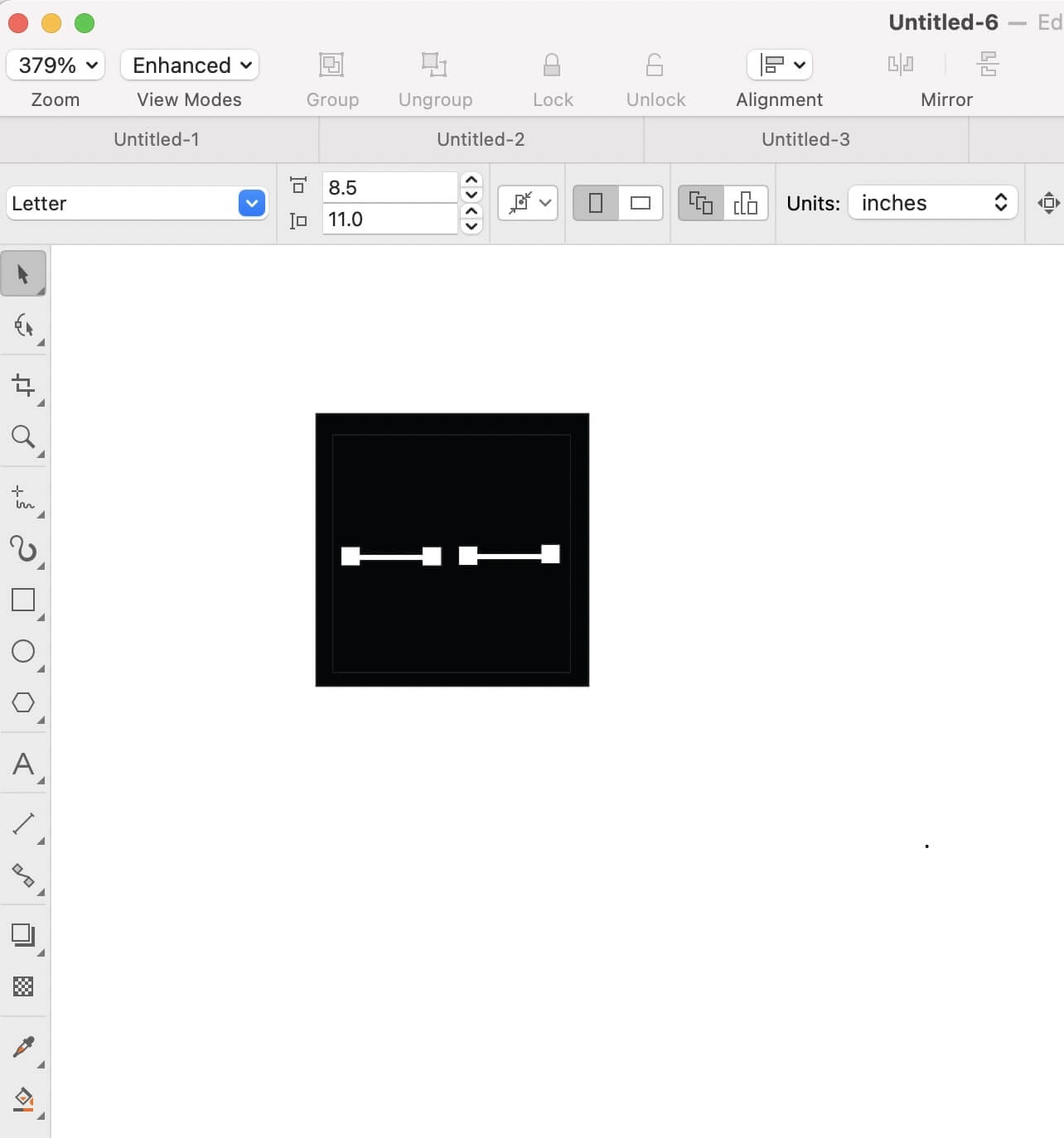
3) I exported this as a DXF and opened the file in coreldraw. For each piece I drew a square around it of equal length. and used the smart fill option in coreldraw to make things black and white and I then exported the file as png - ready for mods.
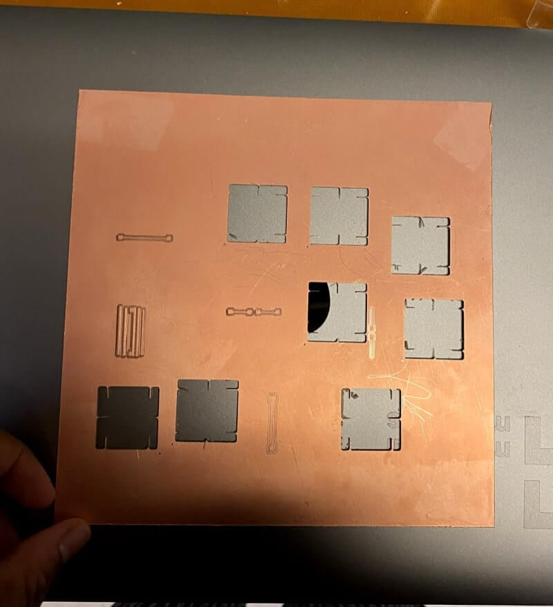
4) I printed a bunch of these pieces - the thickness of the sheet was around 1.51mm - I cut the boards to have joints of width 1.48mm in fusion - but they are still a bit loose
5) Next, I assembled them
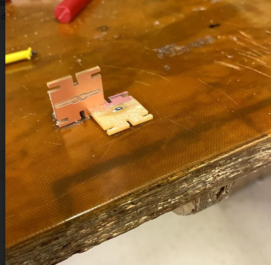
6) Soldering this was a pain, till Zach pointed out that we had a clamp I was soldering with just my fingers to hold it in place and I was using the stiff yellow wires which don't have a lot of bend to them. I would have given up but I spend a lot of time making the joints so I stuck with it. And in the end
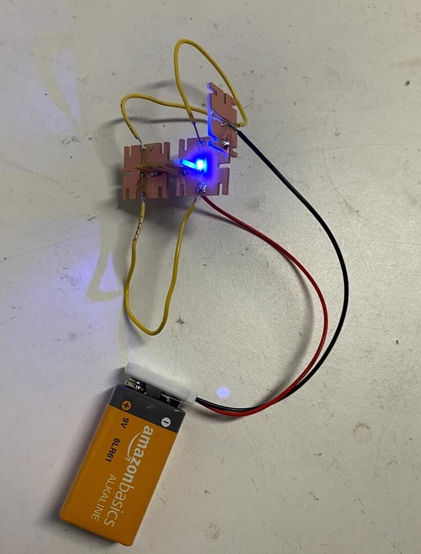
7) immediately after I dropped it on the floor
I also learnt that I can mill wood in the Roland SRM20. I had a bit of conductive ink at home from bare conductive electronics company. So I went and made a vinyl stencil and then poured ink through it on to a wooden piece
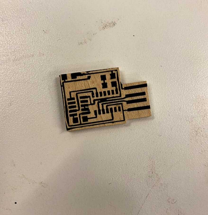
It looked pretty. And my plan was to use conductive epoxy that Zach suggested to soldered the components on but I had to remake this board (the edges were a bit off). But Zach also used the multimeter to see that the resistance was pretty high - so the board wasn't conductive ? Maybe I should have used more paint → I probably should have deposited more of the paint instead of just flowing just enough to cover all spaces. Experiments for another time.