Week 5 - Electronics Design
I always wanted to make my own pen plotter. Not for making pen plotter sketches with a pencil/pen but to replace the pen holder with a brush holder so I can do paper marbling (Paint on water).
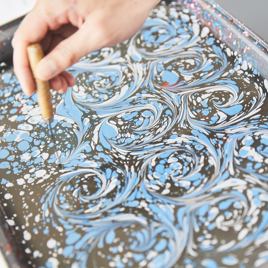
source. - https://artsbenicia.org/paper-marbling/
For that I need two stepper motors and a servo. I first just wanted to get the layout of the board right so I decided to only two stepper motors with SAMD11C14A. I used kicad to make my designs.
I made two boards - One board with peripherals to control the microcontroller programming and pinouts for a motor.
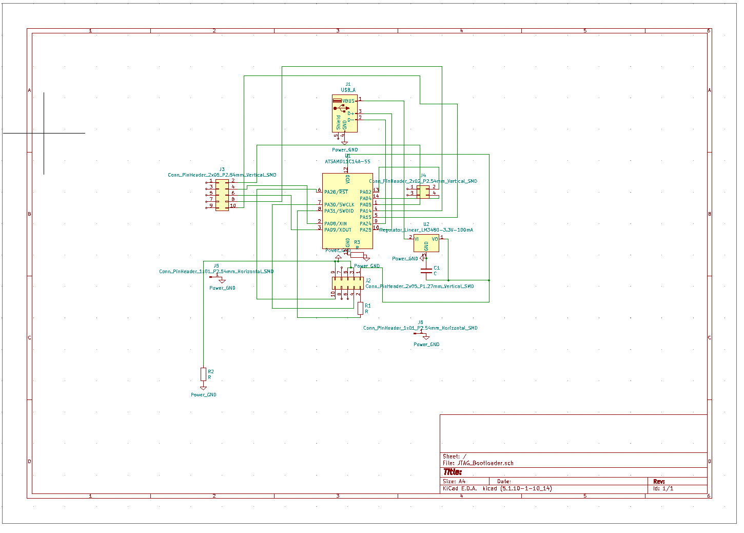
I didn't really care much about the schematic looking clean since I only needed this to generate a setlist for which parts are connected to which parts.
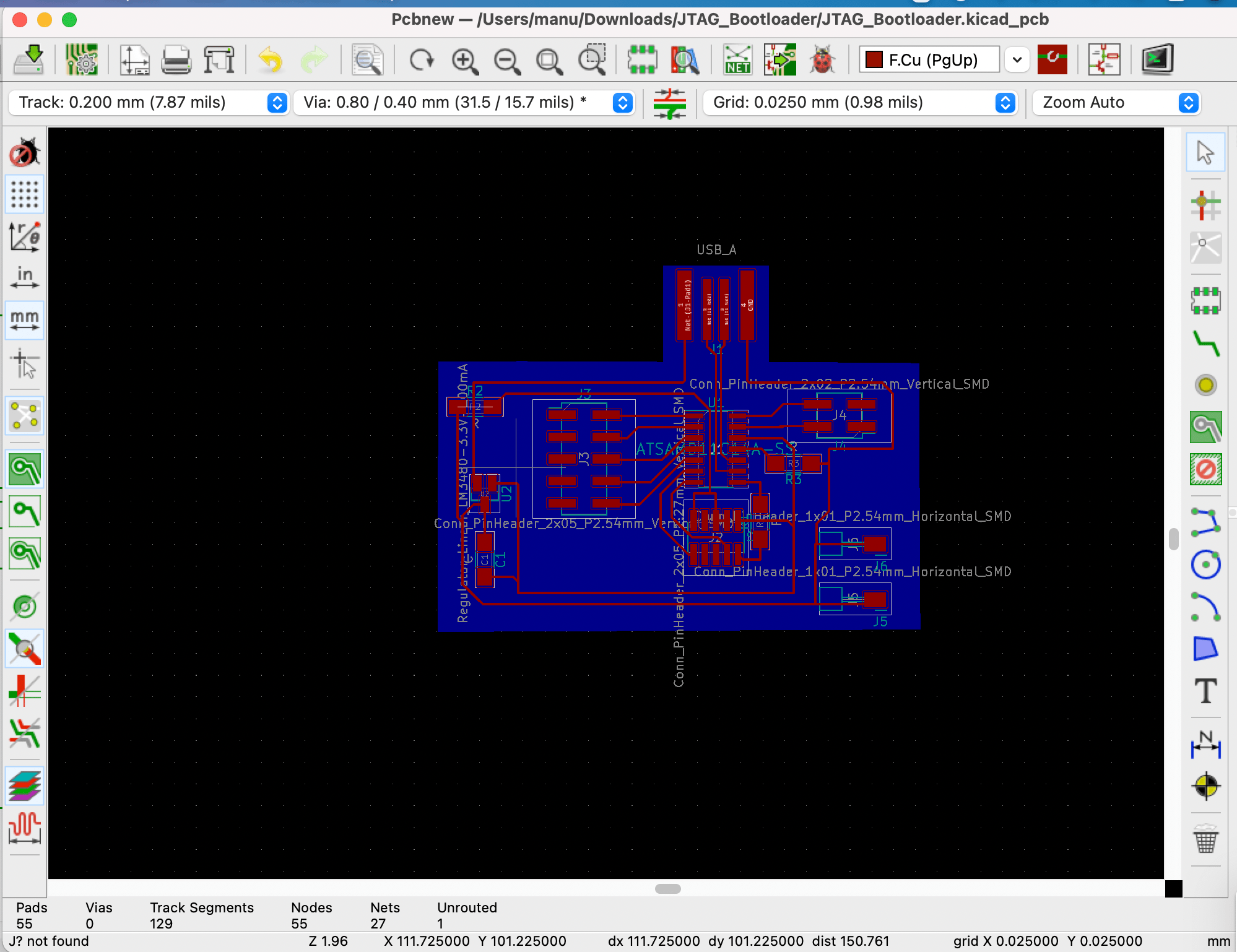
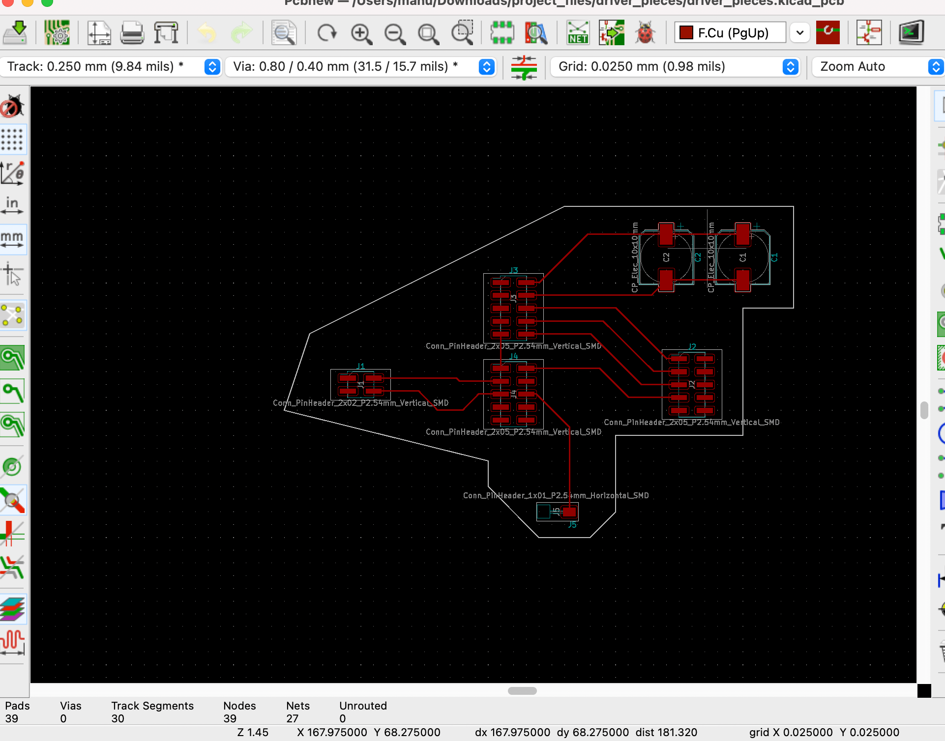
I then made a PCB layout. routing these was a pain. I ended up using R0 resistors as bridge across. Also this image shows a 2x05 header connected to A05,A08 etc - this was the newest board I didn't soldered. the board I soldered I just kept 1x05 pad for connections.
Once I was satisfied with my designs, I messed around with kicad Board setup to try various track widths but ended up staying with the default track widths (you can find the board setup button in the top left hand side of kicad). You can also edit all the track widths and vias together by going to edit → Edit Tracks & Vias properties.
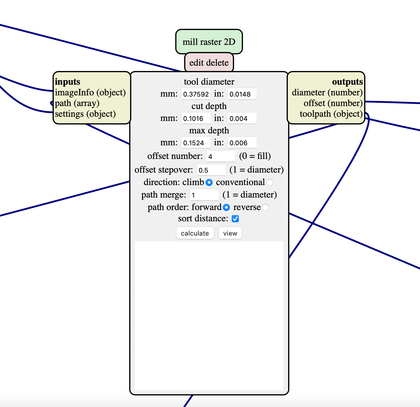
Time to mill. I first milled with the default settings but my traces were too skinny and it didn't really cut through the 3.3 v regulator. So I decided to change the tool diameter in this mod to be a bit lower the actual 1/64 end size
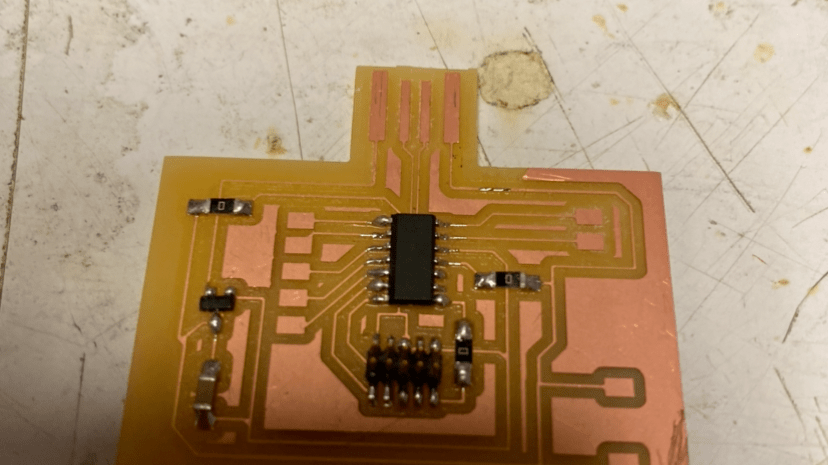
I waited a long long time for the mill to finish (30 min) but at 2AM in the morning it felt way longer. I then soldered the board using some of the things I practiced during electronics production week.
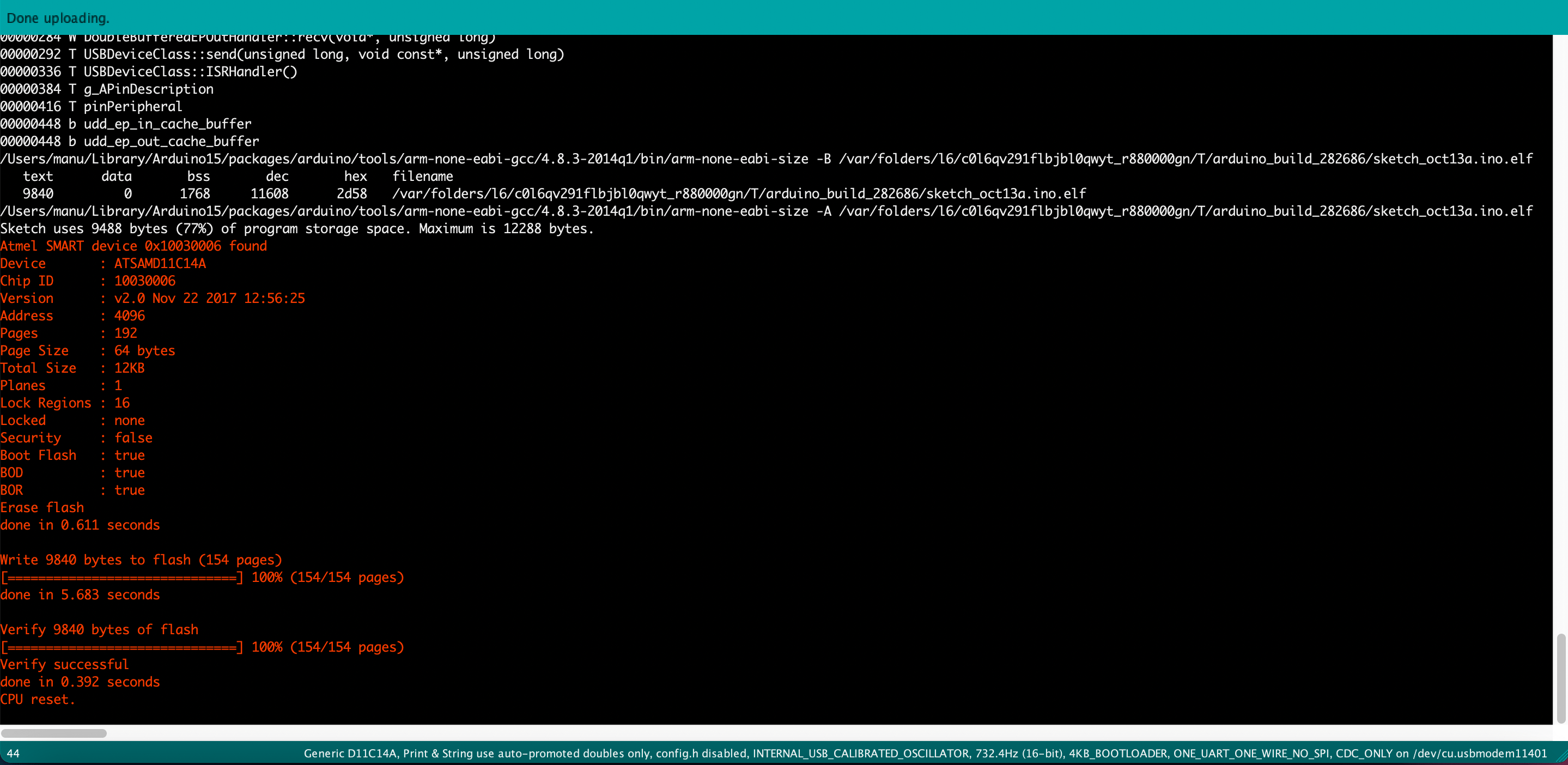
I then programmed it using edbg (Week 2- Electronics Production class page has the details on how I did this).
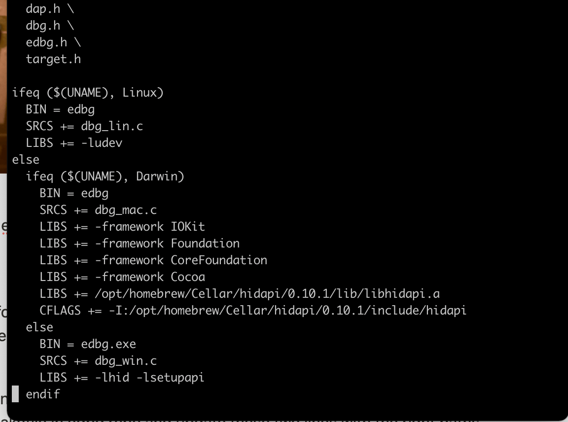
Note - I noticed that some folks were having issues with setting up edbg on their computers. You have to update the make file in edbg repo.
First brew install hidapi. then find where it is installed → brew info hidapi will tell you this. Then copy that path. Go to the Makefile in edbg repo and update these two lines with the right paths. edbg by default looks for it under /user/local/library etc.
I was able to make my board into a boot loader with edbg and my Arduino sketch recognizes it. So I made a Arduino sketch for controlling a stepper motor at A08 and A09 as STEP and DIR. You can find my sketch code In the linked files below. I uploaded the sketch to my new board and it works!
Now to see if the motor will actually work. To drive the motor - I borrowed the DRV 8825 pololu board from Zach. Since it is not mine I did want to to solder it to the board so I came up with a work around that involved a lot of wires!!
I just used a bunch of headers to approximate the motor circuit. one of the capacitors pads was used for supplying the 12v power. the empty ground pad at the bottom was used to solder a wire across to the micronctroller board so everything is grounded together.
The final solder ugly mess looked like this
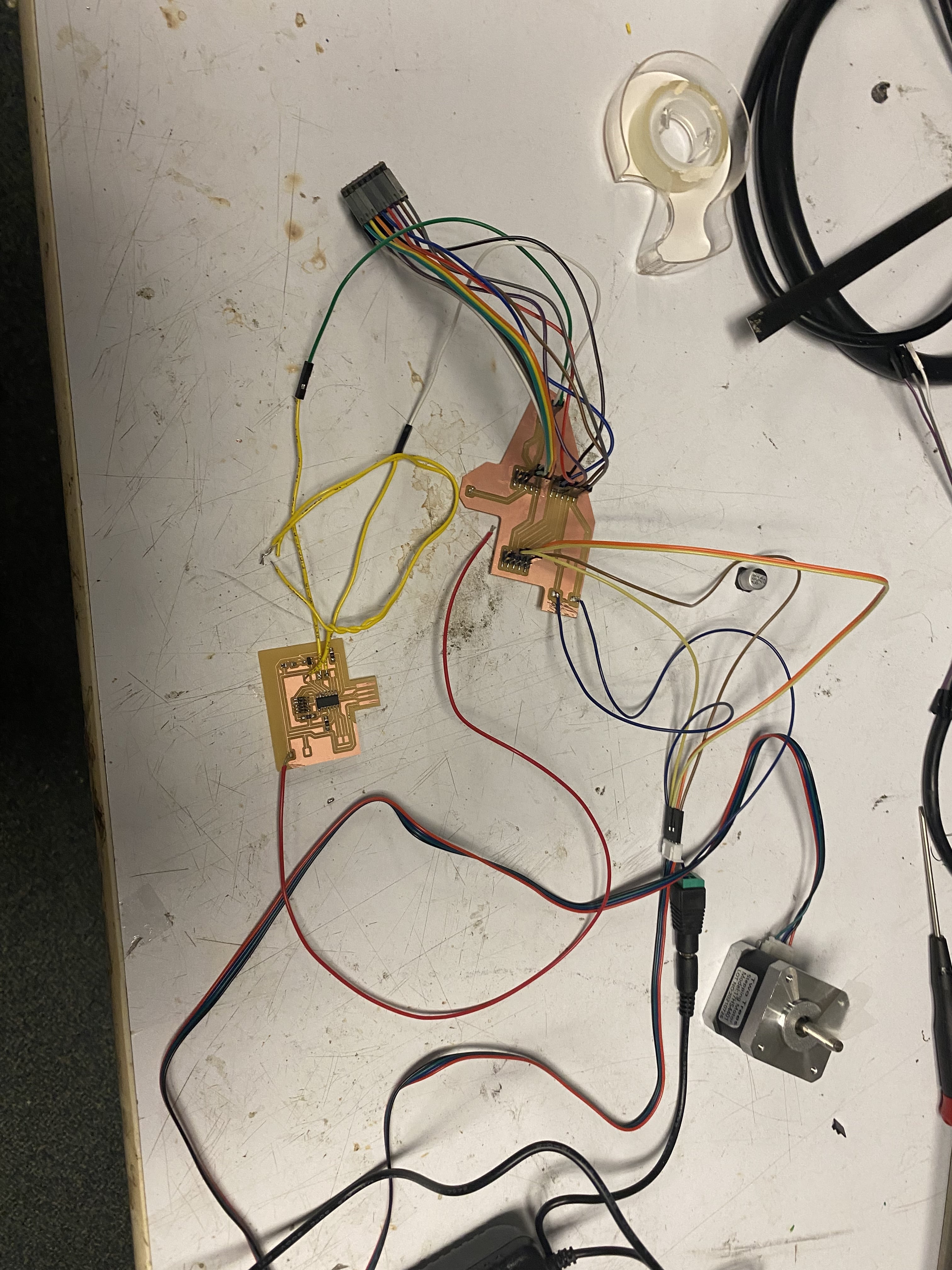
didn't really avoid the wires - defeating the purpose of PCB? Most of the wires are just for Zach's driver I borrowed. When I get my own 16 of these wires won't be there. So I am happy with the design. Also I was an idiot and forgot to solder the wire for RST/SLEEP button. And I was too sleep deprived at this point to do it. So I just held a wire from 5v from usb to that junction on the driver board to test the motor. It worked at first attempt.
Looking at my stepper motor go :O - Really bad programming here with the steps with fix it later when I mill a new board for final assembly of the pen plotter
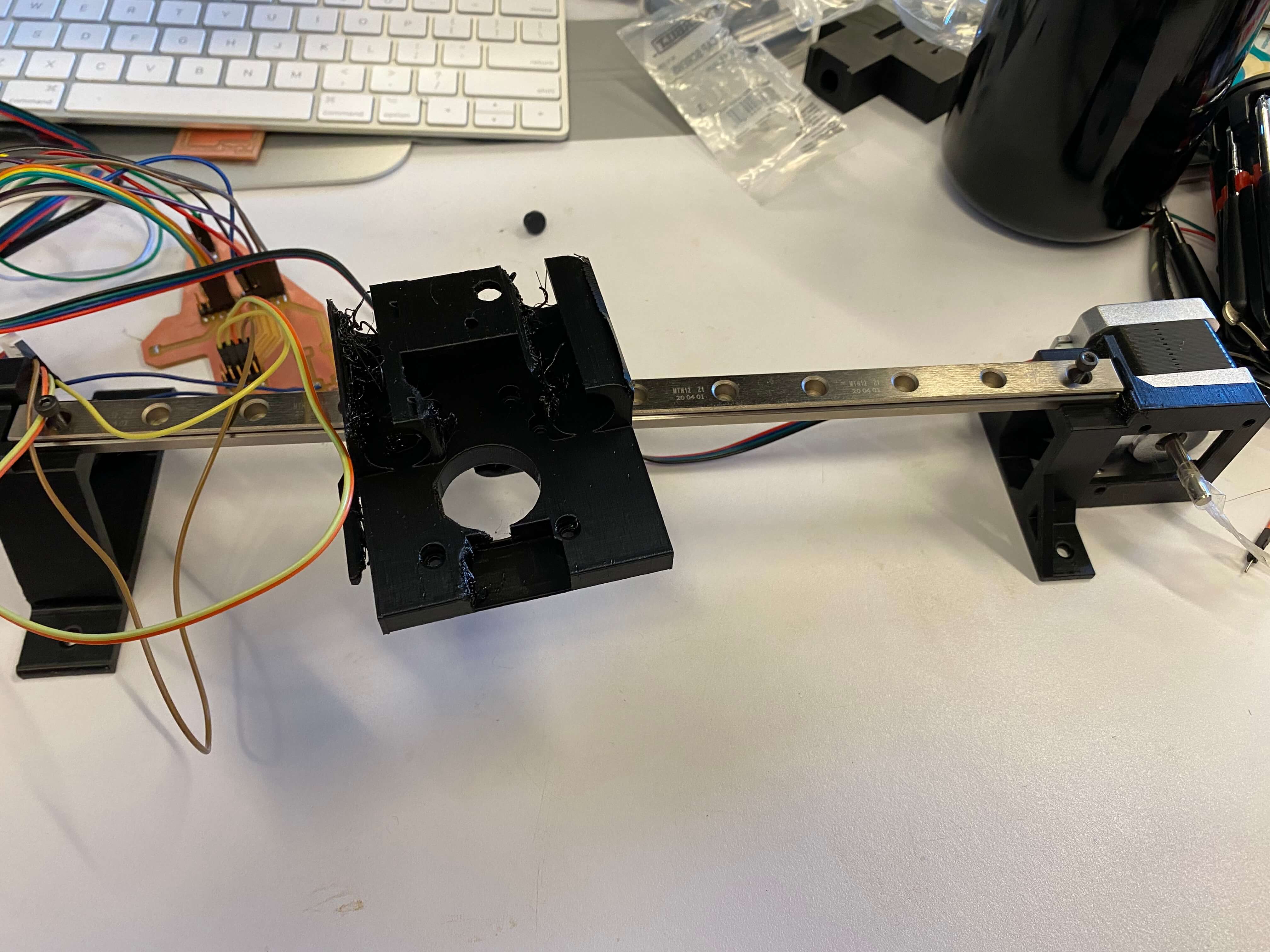
Next, I mounted the stepper motor onto the 3D printed CNC machine - I found on thingiverse - https://www.thingiverse.com/thing:4537916. The raft mount didn't print very well.
All the project files are here - https://drive.google.com/drive/folders/1SQzIsN_tJ4A_ltDeO7BmKSO9FVTFNMeY?usp=sharing