diy centrifuge for DNA extraction
bill of parts
| count | part | price | link/vendor |
|---|---|---|---|
| 168 sq in | acrylic casing | $0.05 per sq in | home depot |
| 1 | bldc motor with esc | $22.88 | amazon |
| 16 | 8/32 3/4" screw and nut | ||
| 4 | 6/32 1/2" screw and nut | ||
| 2 | magnets | $0.22 per magnet | amazon |
build log
- look here for notes that i took while building the project (e.g. measurements, reference pics, etc.)
basic knowledge
- batteries
- LiPo batteries typically listed as 1S, 2S, 3S, etc. each
Srepresents a battery cell, which corresponds to more voltage: - LiPo batteries also have a discharge rating (“C” rating). the discharge rating describes the maximum number of amps that can be safely pushed from the battery
- LiPo batteries typically listed as 1S, 2S, 3S, etc. each
cad
- the centrifuge should be able to spin these 1.5 mL Eppendorf tubes.

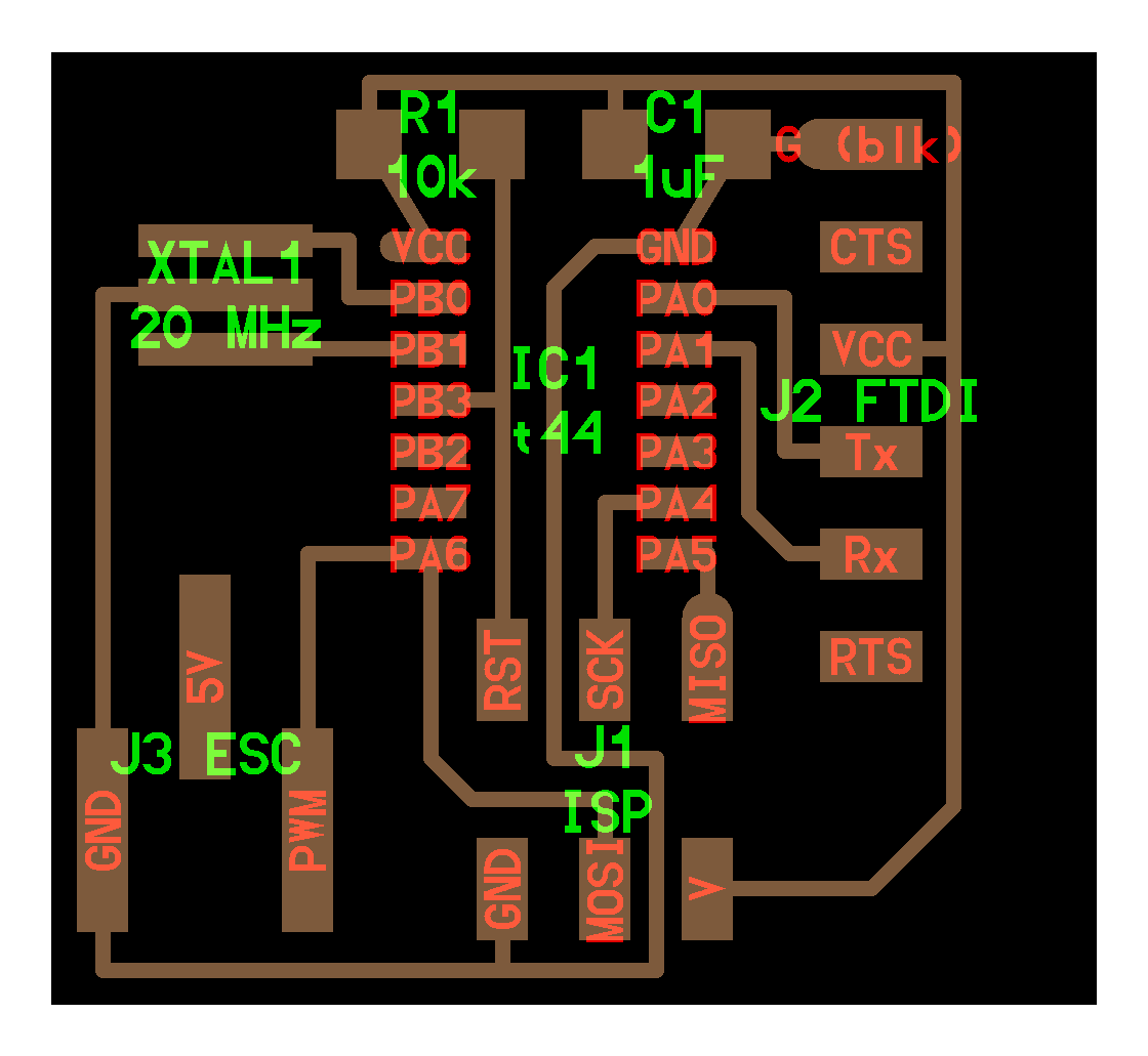
board
- i had to mill the board five times to complete the final project: what a time...
- the first board i made was very tightly packed (even following the
fab.drudesign rules) and resulted in a board with weakly adhered traces. likely, i also weakened the traces during the soldering process; this resulted in me ripping the traces off when i tried to disconnect the JTAG programmer cable from the board - the second board had a major design oversight: somehow, i didn't realize that my USB header was flipped, and so the 5V and ground traces were flipped. this meant that as soon
- i tried to cut traces and wire jumpers, but because of the way i had laid out the board, this turned out to be pretty much impossible, and i opted to redesign the board.
- the third board was correct, but the 1/64 endmill had become dull by the time i was milling, and broke during the milling process
- the fourth board worked — annoyingly, i also ripped a trace off when i was trying to clean up the board of stray traces to prevent shorts, which made me have to remill the board
- finally, i got a beautifully milled board (the z-height was still a little too low, making the traces almost engraved rather than a thin layer), that i soldered correctly without problems
- the first board i made was very tightly packed (even following the

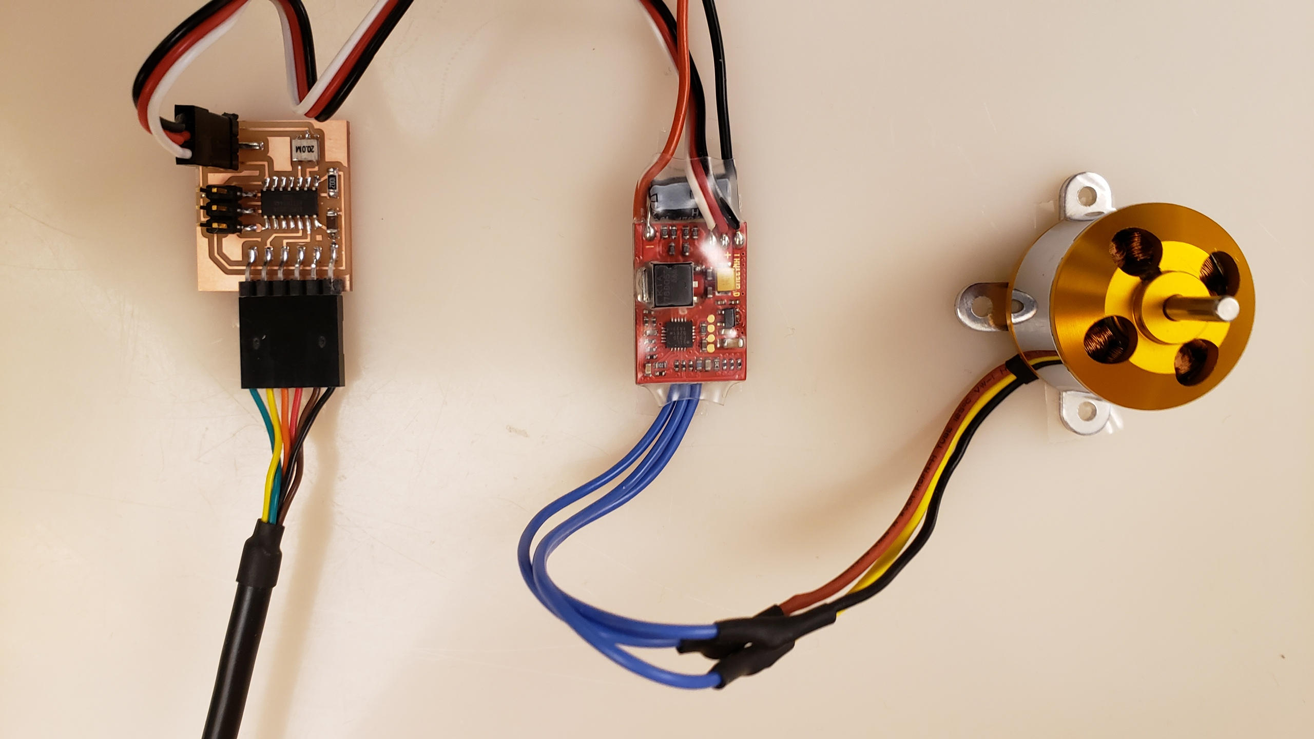
ESC motor
- calibrating the ESC motor. probably the most annoying yet also satisfying moments was getting the ESC motor calibrated and running.
- the calibration protocol (standard for most ESCs, and was also described on the Amazon vendor's page)
- power on with uC sending high pulses, wait until beeps
- turn off
- switch uC to send low pulses
- turn on
- wait for beeps
- turn off
- next time the motor is powered on, it will be calibrated
- the first issue was sending the correct signal to the motor. at first i was thinking that the calibration protocol i was using was incorrect, but it turned out that wasn't it
- in a streak of luck, i realized that the ESC probably wasn't even receiving the pulses i thought i had programmed the uC to send
- debugging using the oscilloscope confirmed this; pin 5 that i was using to send the PWM signal to the ESC was not outputting high voltages.
- after cutting traces, wiring jumps, and linking pin 16 to the ESC, the calibration protocol worked, and i was able to get the motor to run.
- the calibration protocol (standard for most ESCs, and was also described on the Amazon vendor's page)
- i was also wondering where the power (5V) came from in the ESC demo board (components); i think it's not actually a used connection and that voltage comes from the external source that powers the motor.
the case
- designing the case was the most interesting part of this week, since i hadn't done any integration in the previous weeks before
- i was a little annoyed because i had designed a case in Fusion at home, but forgot to the save the project (i didn't lose the CAD, it just didn't upload to the cloud), and i had to re-CAD it when i got to campus
- instead of re-CADing the whole thing though, i just remade the geometry of the faces, and exported them to DXF to be cut on the laser cutter
- acrylic has very good tolerances with respect to kerf, and so the measurements that i
- i actually made a mistake in the size of the mounting holes for the corner braces that would connect the acrylic sides together, but it was okay because we had bolts and nuts of a larger diameter that could fit into the holes
- 3d printing the corner braces actually took way too long, but i was very pleased with the results
