How To Make Almost Anything Neil Gershenfeld

MIT Center For Bits And Atoms
Fab labs share an evolving inventory of core capabilities to make (almost) anything, allowing people and projects to be shared. These are my projects.
Electronics Design -
Echo hello-world
10.13.21
assignment
group project: use the test equipment in your lab to observe the operation of a microcontroller circuit board
individual project: redraw an echo hello-world board, add (at least) a button and LED (with current-limiting resistor) check the design rules, make it, and test that it can communicate extra credit: simulate its operation
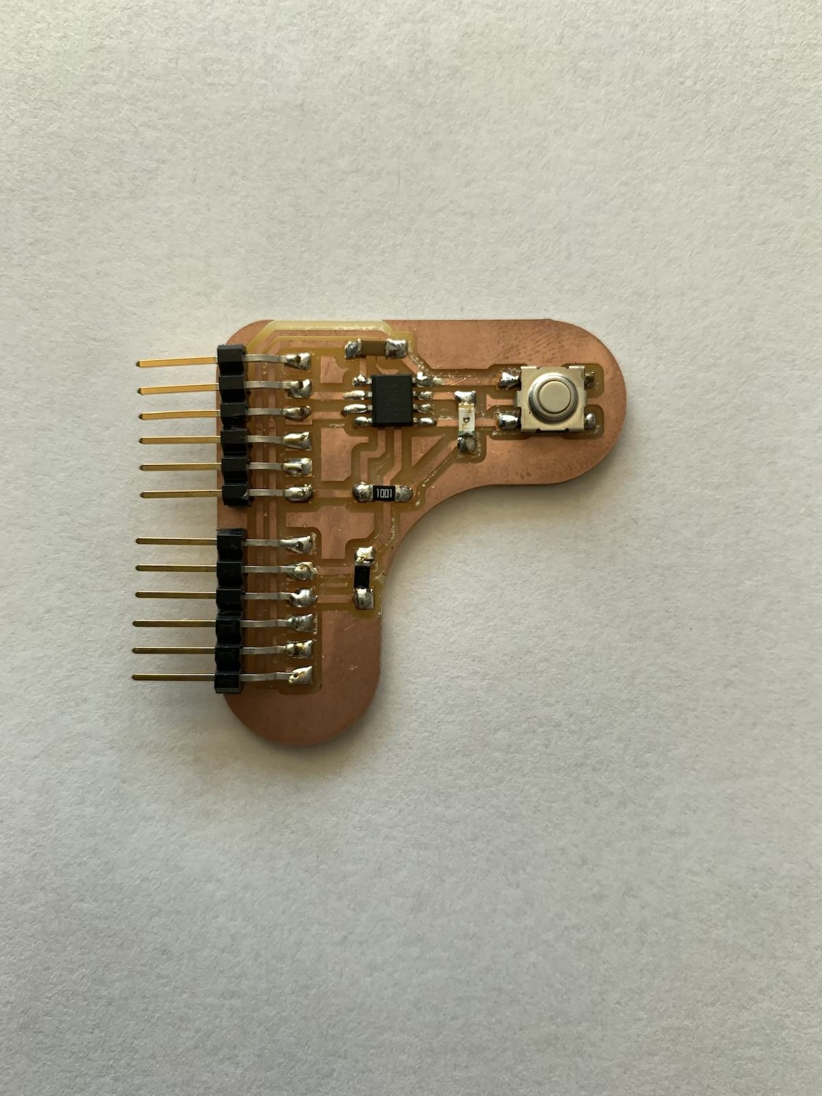
[1] To begin Electronics design, I chose an ATtiny412 microcontroller which was recommended to those who were new to Electronics and PCB (Printed Circuit Board) design. From the software that was offered (KiCad and Eagle) in the recitations, I decided to learn and follow the tutorial for KiCad as it is open sourced and free to use beyond my academic years. It was quite challenging, as I quickly realized everything that I didn’t know about electronics. In my design I used mostly wires, although (in later weeks) I discovered I could use labels to make the schematic design easier to read. I decided to add a button and a LED Light to the design The LED needed a resistor, and the button was connected both to PA1/SDA and to ground. During this process it was important to have imported the FAB library to guarantee we will be using the components that can be found in the fab labs in our designs.
The PCB layout for routing was a rewarding part of the process, as it allowed me to see what I had designed so far, and the different components size and proportion on my board. It also allowed for some creativity in the location of the components and in the design of the outline of the board. For this initial design, to keep new variable to a minimum, I decided to keep the shape and outline standard (I only rounded the corners, who said PCB can’t be a little softer). For key considerations in drawing the traces see below.
Programing the ATting412 using UPDI proved to be the most difficult part of all. This required a bootloader and even then, it seemed to encounter a constant error with my Mac computer. I later found out that ATTiny relied on Linux operating systems more heavily (Maybe I should have tried programming it is using Linux), so I asked Rob Hart for help. Rob helped me program my board using the Blink program in Arduino, and I managed to get it working. Observing the light go on as I clicked the button was quite satisfying.
Considerations:
- When drawing traces, it is best to give yourself enough room while you gain experience, tighter boards are harder to achieve.
-Start out with the traces that only have one possible path, such as all the ones connecting to the microcontroller, then move on to Ground and VC. Ground and VC are a little more variable in their paths so they can tolerate variations and different paths.
-When all else fails, and no more traces can be achieved without crossing an existing trace use a 0ohm resistor as a bridge.
-Make sure your solder tip is always tinned.
-Use flux while soldering, it makes it easier.