How To Make Almost Anything Neil Gershenfeld

MIT Center For Bits And Atoms
Fab labs share an evolving inventory of core capabilities to make (almost) anything, allowing people and projects to be shared. These are my projects.
Input Devices
10.27.21
assignment
individual assignment: measure something: add a sensor to a microcontroller board that you have designed and read it
group assignment: probe an input device's analog levels and digital signals
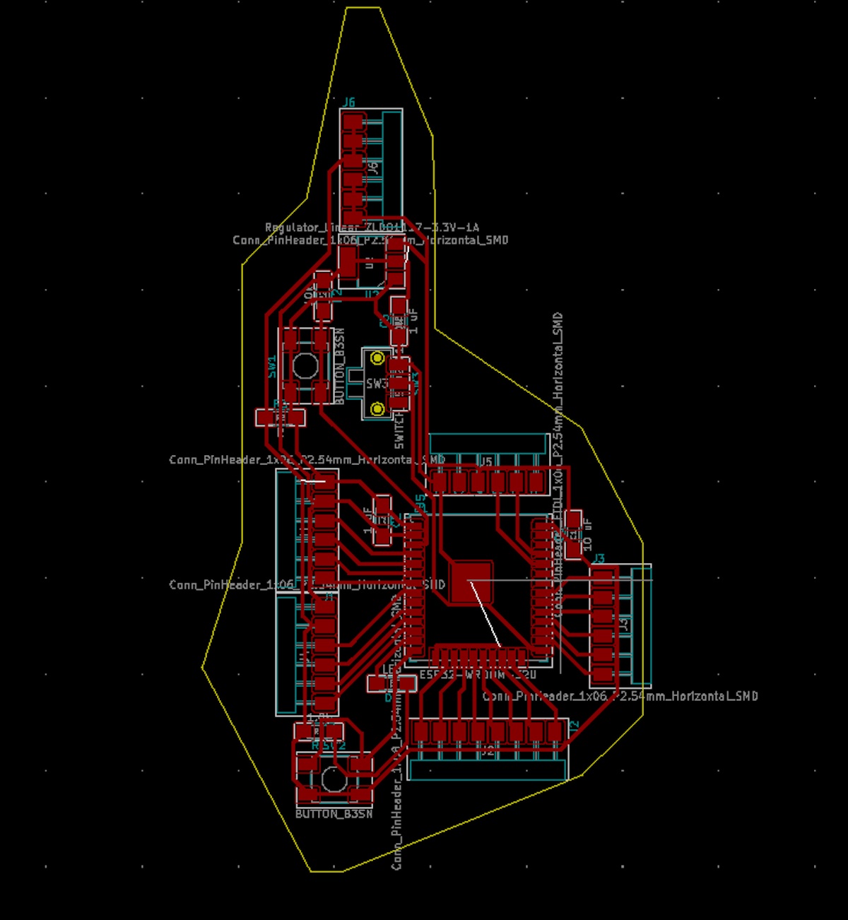
[1] Looking at the weeks to come, I decided to attempt creating a large new board with many pins that I could potentially use for both my final project, but also for Input/Output and Networking. For this, I decided to use an ESP32 microcontroller which has many pins that can be used for almost anything I might need, and also which has WIFI/Bluetooth for Networking week. ESP32 also has the added benefit that it doesn’t require programming using a bootloader, which was something I struggled with when I created my ATTtiny and D11. Although I had already designed and milled a board before, I had mostly based my design on an existing board, adding only an LED light and a button.
For this reason, creating a board from scratch for the ESP32 was a lot harder than I imagined. As I had focused on Latin America earlier, I wanted to continue pursuing this theme, and designed my board to be shaped like South America, the South American ESP32 PCB. For this board, I mostly followed the steps described in Week 5, with a couple of differences. I learned that it is very difficult to have Ground and Voltage pins next to Pin Headers all around the board, so I only included ground and voltage headers in a couple of places and then in the southern tip of the South American PCB, I created a few pins all dedicated to ground and a few pins all dedicated to voltage.
As the ESP32 board I was designing receives 5V through UPDI, but the ESP32 chip can only take 3V, I had to include a regulator. Understanding this was a crucial step. Also, it made me realize that it would be a good idea to have header pins for both 5V and 3V; as some Output and Input sensors might require different voltage.
Being able to create the traces for all the different headers I wanted, while maintaining the shape of South America was more difficult than I thought. I ended up using 2 different 0 ohms resistors to be able to bridge traces that I couldn’t connect otherwise. I also used the space under the ESP32 to run traces from one side of the board to the other. A problem I faced this week, was that I didn’t know I couldn’t flip components. I was so used to CAD software/3D modeling, that during the design process, I flipped some components to be able to maintain and achieve the desired shape.
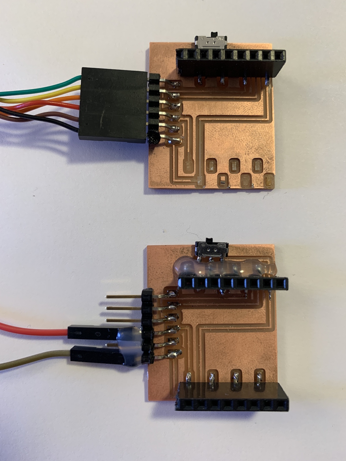
After milling, soldering, and creating the final version of my South American board, I realized the problem with using the flip (mirror) functionality. As I had flipped the components, the ESP32 was soldered incorrectly. I had spent a lot of time developing this board and needed to have an Input device. So, I decided to mill the ESP32-Cam board on the HTMAA website and play around with capturing images. I will have to delay fixing the board I was designing for Output Week.
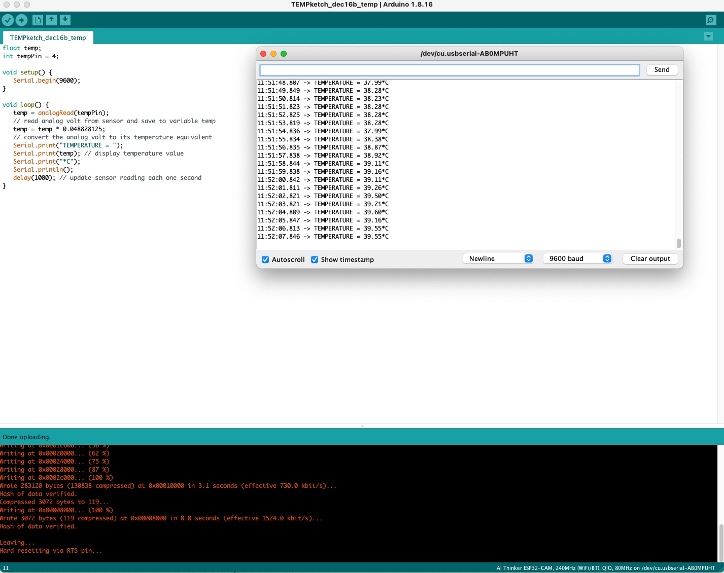
Update: After creating/designing my own board for output week, I came back and added a temperature sensor to that board to have temperature as an input. This made me think I could add temperature as well as the ESP32-Cam to my final project.
Considerations:
-Add both 3V and 5V header pins to a board you design.
-Don’t flip components in KiCad, flipping/mirroring is only to be used to design two-sided board. Again, I think I need to learn how to design and mill two-sided boards at some point.