How To Make Almost Anything Neil Gershenfeld

MIT Center For Bits And Atoms
Fab labs share an evolving inventory of core capabilities to make (almost) anything, allowing people and projects to be shared. These are my projects.
Output Devices-
10.27.21
assignment
individual assignment: add an output device to a microcontroller board you've designed, and program it to do something
group assignment: measure the power consumption of an output device
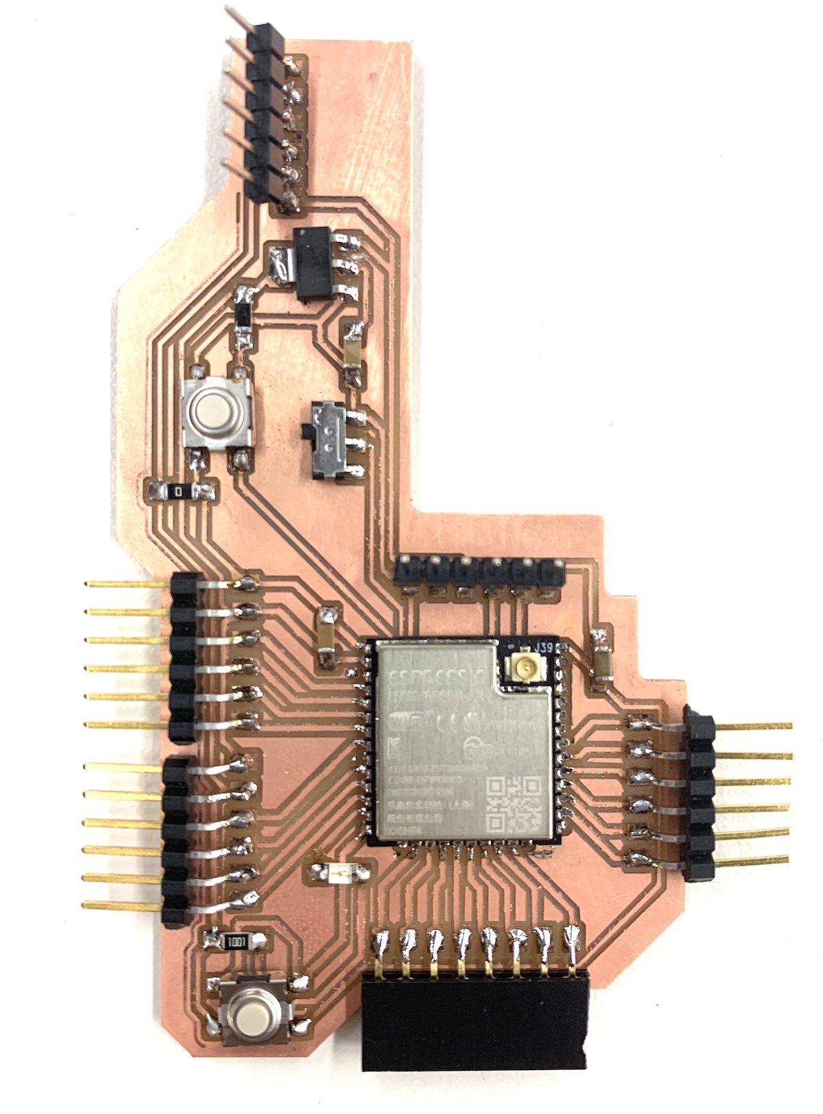
[1] This week I continued what I had begun last week, to essentially, create and design my own “Arduino Board” with an ESP32 brain and multiple Pin headers to connect any/almost any input/output devices. I began by taking my failed board design from last week and redesigning it without any of the mirrored or flipped components. I had learned my lesson. It proved to be more difficult than imagined. It is easier to create traces and plan a board when you can flip components to your benefit. Without this, it was more difficult.
After doing this I realized I had to abandon my initial idea of having a South America shaped board and had to settle for a “b” board. It was a coincidence, but my name being Benjamin, it was nice to have a “b” shaped board. For this design I included an LED and an additional button I could use to control one of the header pins. Again, I designed traces in KiCad, milled, soldered, and finally my very own multipurpose board.
For this week, as last week I only used an ESP32-Cam to capture images, I decided to try out a temperature sensor as an additional input to try on my new board, and, an LED Display. To do this I realized I needed to download some additional libraries for the LED Display (see attached). After a lot of programing, I managed to get the LED working, but to my disappointment, it wasn’t as bright as I would have liked. It seemed as if the backlight wasn’t on. After some research I realized that I needed to join to pins in the back of the LED to get the backlight working with the voltage that was supplied to the LED. Additionally, the LED required 5V instead of 3V. This took me a while to figure out, so I was glad I had prepared for this, and had included both 3V pins and 5V pins to the design of my board. Using Arduino IDE, I edited a code which allowed me to control and send messages to the LED. I decided to write “Hello, HTMAA2021”. The readings from the temperature sensor, and my exploration with temperature can be seen in an update to Week 10- Input devices.