3D printing and 3D scanning are something I often heard of, and I was mildly aware of for maybe 10 years.
I don't know why, but I never get exiceted and enthusiastic about these technologies....until now.
# 3D printing
This is definitely where I spent most of my time this week, and what I got most excited about.
## Group assignment: test the design rules of the printer
**This part will go into the Harvard group assignment page later.**
I decided to study the impact of the print settings size on the minimal feature achievable on a printer.
Joon suggested that the best we can reach with these Prusas (Prusa i3 MK3s) is 0.2 mm, which is half the size of the nozzle.
I tried to print the [wall thickness example](http://academy.cba.mit.edu/classes/scanning_printing/Form3/thickness.jpg) with the 0.3 mm DRAFT and with the 0.05 mm QUALITY settings.
Already PrusaSlicer understands that certain features cannot be printed: with the 0.3 mm was the smallest it attempted to print was the 0.7 mm, while with the second settings it printed up to the 0.5 mm.
This is a sign the printer knows that it needs to print features stictly larger than 0.4 mm, which is the nozzle size.
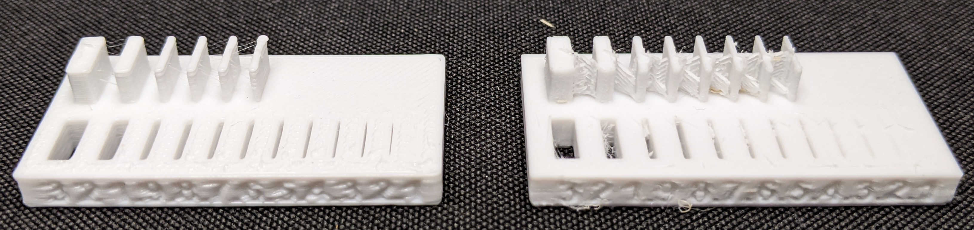
The printer goes to smaller features sizes with this setting, but it produces a lot of artifact.
For what regards the dips, it actually does not improve the reach, which stops at 0.2 mm for both cases.
I want to try again with the 0.2 mm settings in Prusa Slicer.
Remarkably, the printing time was quite different, from around 30 minutes to more than 3 hours.
## Warm-up project: replacement part for my dishwasher
The first piece I designed and made was a wheel for the upper basket of my dishwaser which was broken.
This part is probably possible to make subtractively but I guess a bit annoying, definitely more suitable for a classic plastic mold.
I am very excited by the idea of making cheap replacement parts for things that break, to make them last longer, then more suistanable.
  
After understanding that 3D scanning would not be as accurate as I would like to, I took measurements of a good part with a calliper and made a CAD model for it. [FreeCAD](./models/dishwasher_part.FCStd)
[STL](./models/dishwasher_part-main.stl)
I then printed in two materials: the classic PLA (white) and PETG (orange).
In fact, I learnt that PLA has a glass transition around 60 C, while PETG is a bit higher.
I thought that both would have probably undergo the transition and become smushy, but after leaving them in the dishwasher for one cycle, they turned out fine (perhaps mydishwasher is quite old and does not reach these temperatures...).
I then installed the PETG one in the dishwasher to test it under load, and it has been fine for a couple of cycles.
I will now proceed to also test the PLA one under the load of the full basket in a cycle.
An important parameter for these kind of project is the infill.
I chose infil 50% in a naive way, and it seems it worked. I am not sure if a lower infill would have worked too, and I believe the only way is to test it.
## More seriously (and artistic): stereographic projection
A projct I wanted to do is a demonstrator of the stereographic projection, that maps a sphere in a plane (plus one point at infinity, but let's not bother with mathematical details).
An example of this is the [UN logo](https://upload.wikimedia.org/wikipedia/commons/thumb/e/ee/UN_emblem_blue.svg/512px-UN_emblem_blue.svg.png), which shows the stereographic projection of the Earth as seen from the North pole.
I CADded a sphere surface as interesected by light rays coming from the top of the sphere which projects squares on the plane. [OBJ](./models/stereographic_projection_60mm.obj) [STEP](./models/stereographic_projection_60mm.step) [STL](./models/stereographic_projection_60mm.stl)
In this way you can see how the usual Cartesian gridplane gets mapped onto the sphere surface.
Designing this made me learnt more about CAD, and gave me a better understanding and practice of open and closed bodies, lofts, thickness, and intersections.
I first made a prototype (5 cm diameter) and then scaled it up to the scale I wanted (12 cm diameter).
For the prototype, I tried both 0.3 and 0.2 mm in the print settings.
The 0.2 mm did not work, as I think the base was too thin and did not hold it in place at this size.
<video width="300" controls>
<source src="./vid/time_lapse_printing_red.mp4" type="video/mp4">
</video>
 
 
Several features are interesting: the overhanging parts made a lot of spaghetti, as, especially in the points where they connect to the vertical parts, the angle is close to 90 deg.
They nevertheless worked and held in place.
<video width="1000" controls>
<source src="./vid/demonstrating_stereo_projection_red.mp4" type="video/mp4">
</video>
I was inspired by [this discussion](https://forums.autodesk.com/t5/fusion-360-design-validate/stereographic-projections-with-fusion-360/td-p/7751860
) and [this model on Thingiverse](https://www.thingiverse.com/thing:202774).
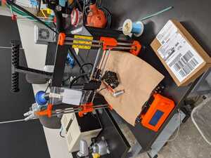
## Repairing a broken Prusa
I have seen a broken Prusa in the lab since the very first day, and I ended up at the rigth time when the repalcement part arrived and Joon was looking for someone to help.
I was eager to help as this was the perfect occasion to learn more about the printer and being able to troubleshoot and repair the machine when problems happen (as they will happen during the semester).
**This part will go into the Harvard group assignment page later.**
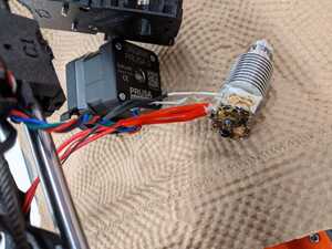
This Prusa had a clogged nozzle, which was probably caused by a disfunctional sensor in the nozzle.
Joon decided to order the entire replacement part, we will investigate if some of the pieces are functional and can be kept as spare parts in the future.
We removed all the parts that needed to be removed and then re-assembled it by following the instructions. The printer worked!
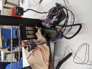
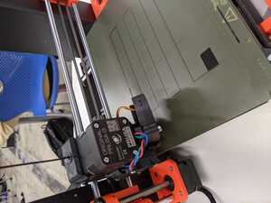
After closing completely the PCB case, however, the printer failed.
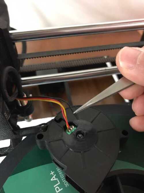
This time the fan that cools down the extruded filament was not working.
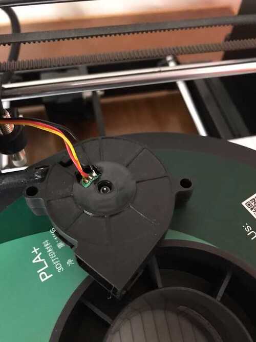
Joon realised that one of the cable was detached from the fan, and that needed to be re-soldered.
Probably, while closing the PCB case, I pulled one of the cable too hard and the connection broke.
Lessons learnt:
- pay attention while tightening screws into the plastic, as you can easily break it with too much force or slight mis-alignment.
- cables are problematic, when they go into the small channels of the plastic: it was enough to pull it a little too hard to detach it from the fan.
# 3D scanning
I feel very enthusiastic about 3D scanning, but I did not spend enough time this week to really dive into that.
I obtained unlucky results this week with 3D scanning, and this is defintiely something I would like to investigate more.
## Sense
I tried to use the [3D sense scanner](https://support.3dsystems.com/s/article/Sense-Scanner?language=en_US) we have in the lab, as the more expensive EVA-5 3D scanner was there only for a few days and I was unfortunately away.
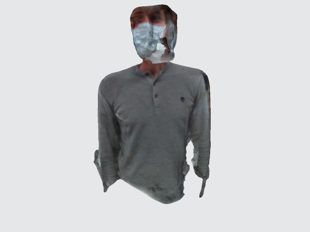
I first tried to scan my body, but the scanner could not scan my hair...understandable but, this is the usual discrimination against curls!!!
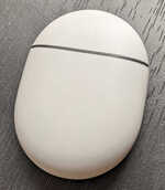
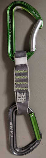
Then I tried to scan two objects: the case of my Pixel Buds, and a quickdraw, used as a protection in rock climbing, which consists of two carabiners and a fabric connection between the two.
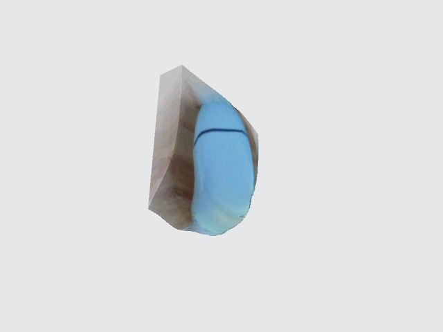 
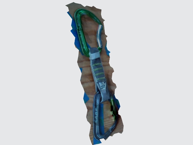 
Results were not satisfying, which might also depend on the fact these objects were both not easy to scan.
The first one, mostly white with few features, the second one with some metal parts which are quite reflective.
I will try it again soon.
## Reminder to try photogrammetry and meshroom
I wanted to try meshroom, but unfortunately I don't have a GPU on my laptop.
I thought about installing it on the Harvard Cluster, which might work but it will require more time and effort, but I found some interesting resources on using it on Google Colab, which I will try soon.
Some friends with iPhone obtained good results with TRNIO, but it is unfortunately not available for Android, so I could not install it on my Pixel.