Discover an in-browser tool to design embedded circuits from js.
This project was inspired from Neil's PCB.py.
This tool is based on frep, a string-based functional representation. In that format, a unit circle would be described as "X*X+Y+Y <= 1".
Evaluating this function for all XY coordinates in a grid provides an image. If a PCB's wires and pads is described as sums of circles and rectangles, an frep string describing the whole board can easily be generated.
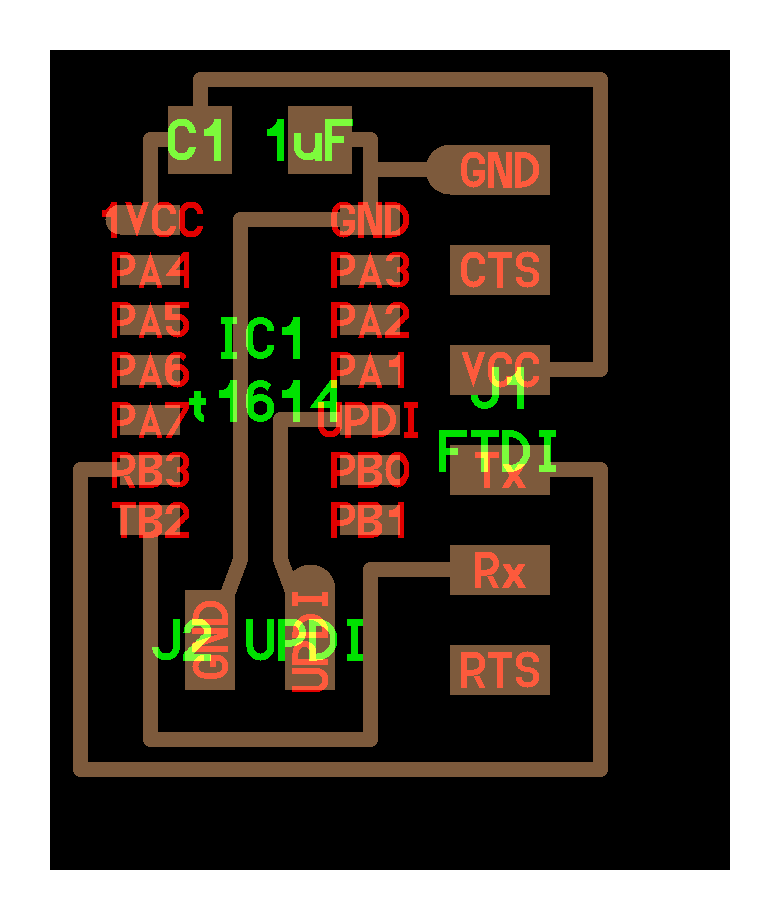
You're surely familiar with Neil's hello world boards, all rendered with this method:
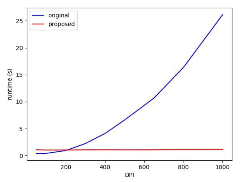
It turns out evaluating the frep quickly becomes a matter of seconds for larger boards. To speed this up, Quentin developed a GPU based renderer with PyOpenGL in 2020. Rendering time went from seconds to milliseconds, but including the frep in a shader required a new C-style syntax with strict typing.
As a challenge, Leo decided to work on a js-based version of the GPU renderer in Spring 2021. This quickly led to a usable tool for drawing boards directly in the browser.
Here is a demo of the js-based frep evaluator, showing a mathematical function. Note that any constant can be dragged with the mouse, try it for yourself!This tool was a breeze compared to the previous Python scripts, but the technical limitations of freps led us to turn to svg for the rendering. Leo's gram language already had all the necessary tools for merging and rendering svg paths, so migrating was fast. The final version of our tool can be found here. Freps are entirely gone, but the API for adding components and wires on a PCB remained unchanged.
A component is an instance of a footprint at a given position and rotation.
Footprints are js objects containing each pad. Each pad consists of:
The component object has the following useful attributes:
A wire is simply a list of coordinates followed by a thickness. This is the best opportunity for referencing pads and component's positions, as it makes wires parametric as well.