Assignment and Idea:
This week came late, as I wanted to build a base for my final project, where I could control an input and output device, and perhaps more, from a microcontroller board, via a wireless connection. I decided that the XIAO ESP32S3 would be a nice platform for this, and the teaching team helped me think through component placement and traces to ensure flexibility for multiple devices. I am planning on controlling two devices, but built a board for three, just to be safe and future-proof to some extent!
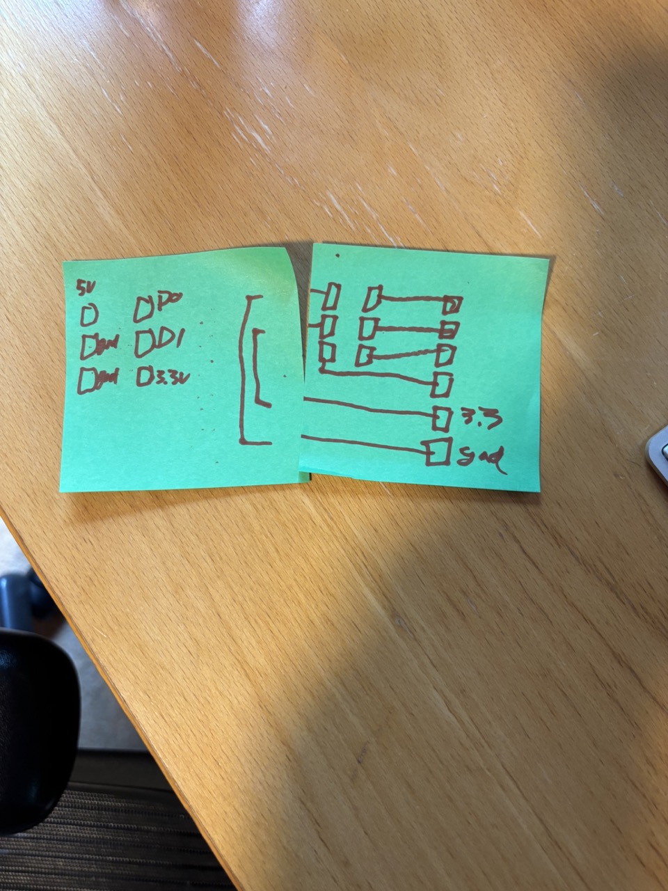
We mapped out a design on some post-It notes:
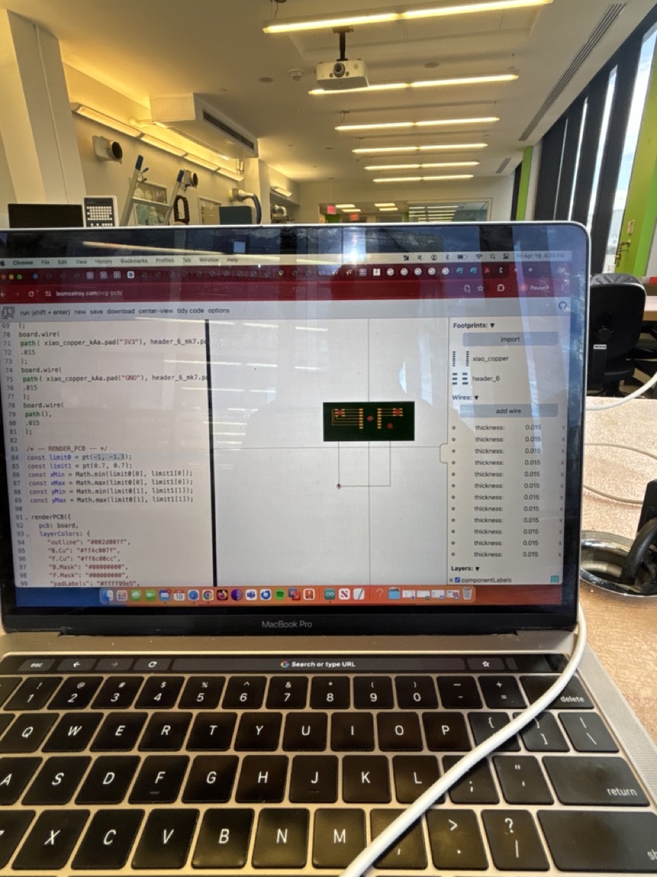
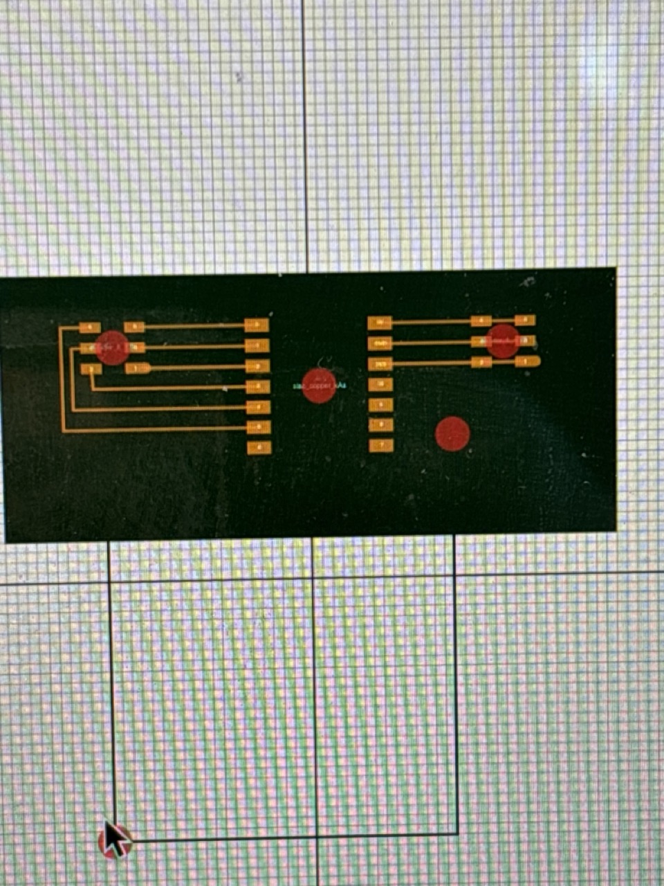
Then converted the design to something more real in SVG-PCB:
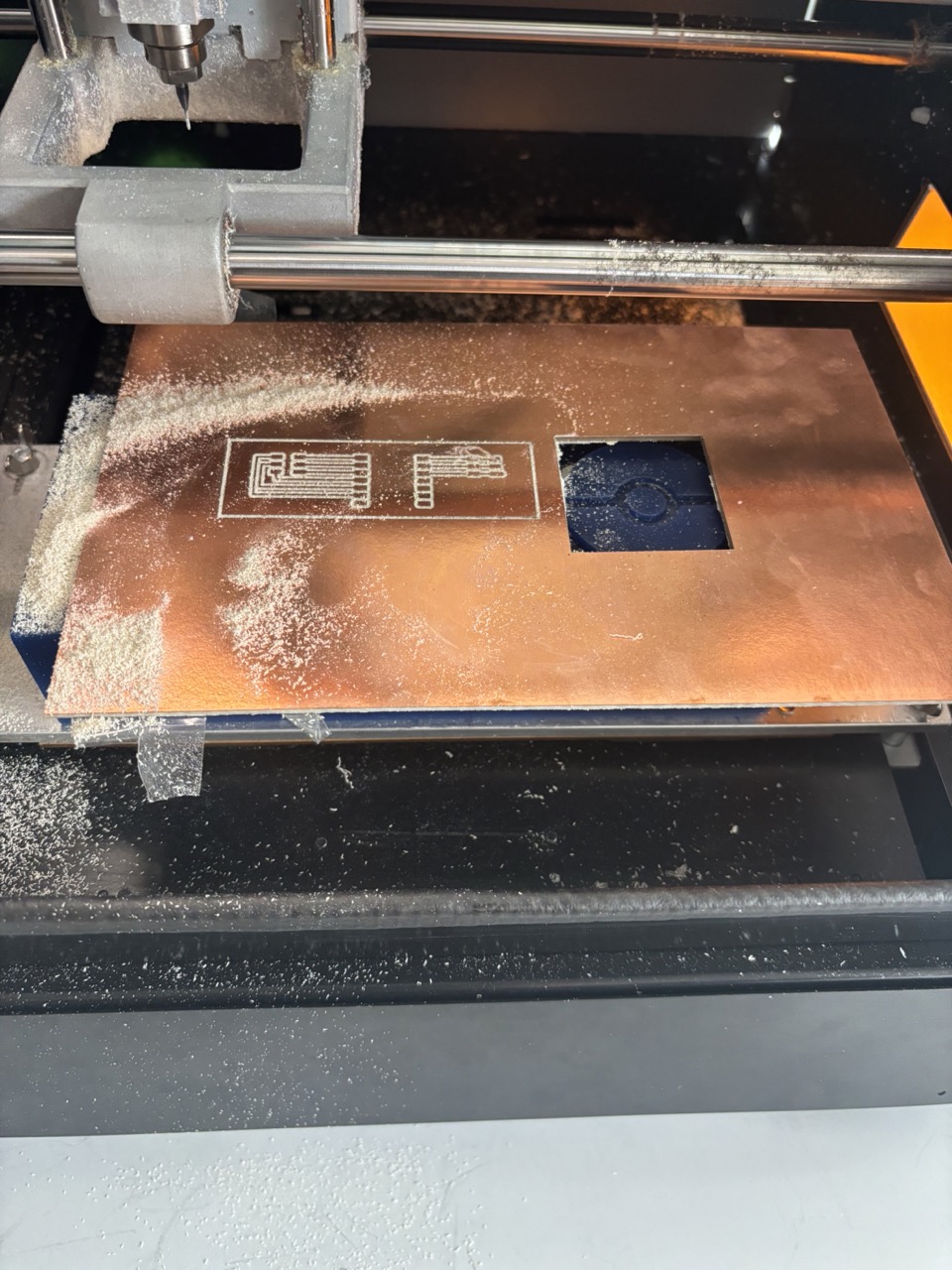
I moved on to Mods in the Harvard lab and started milling:
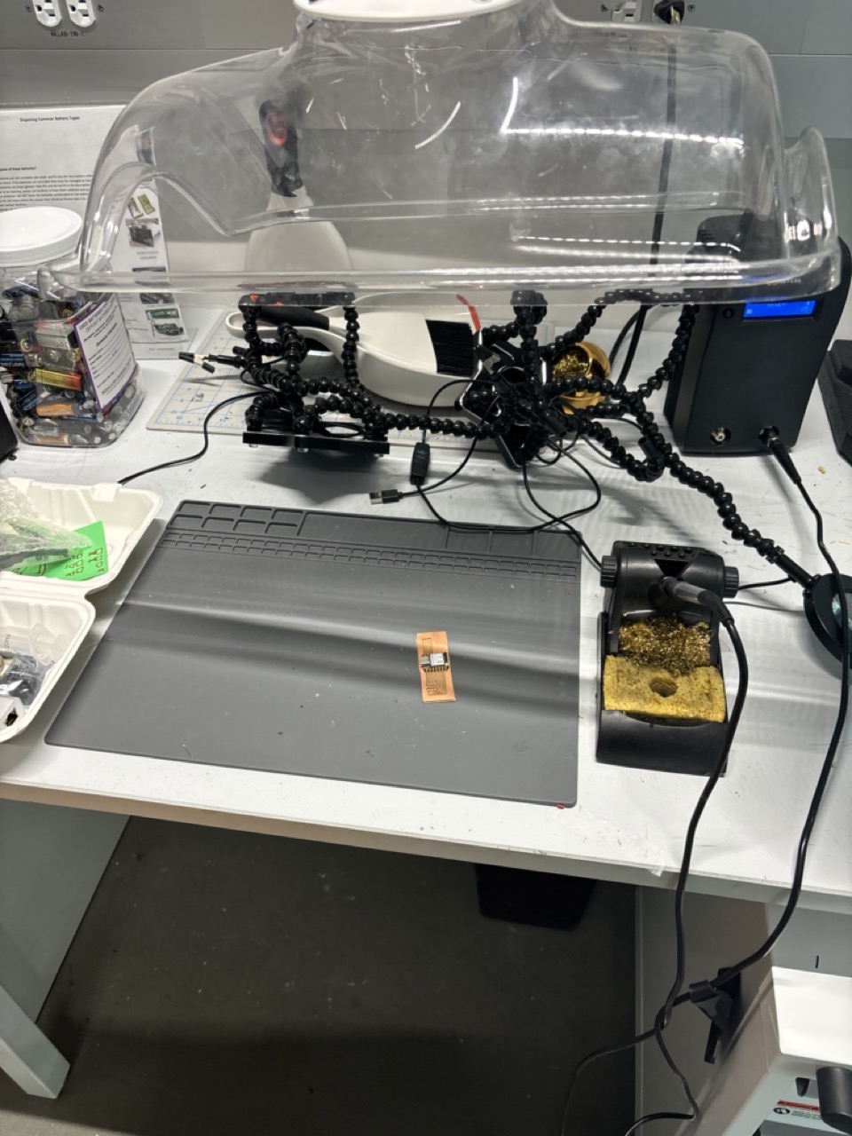
… and moved on to soldering:
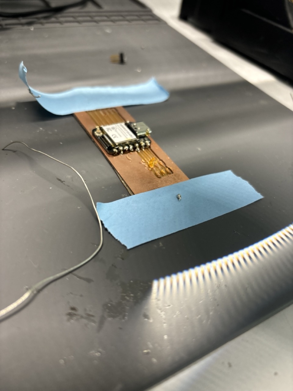
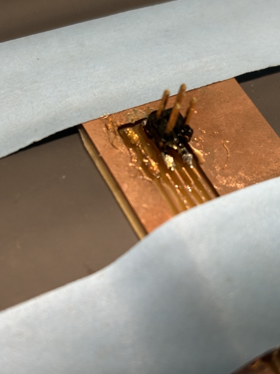
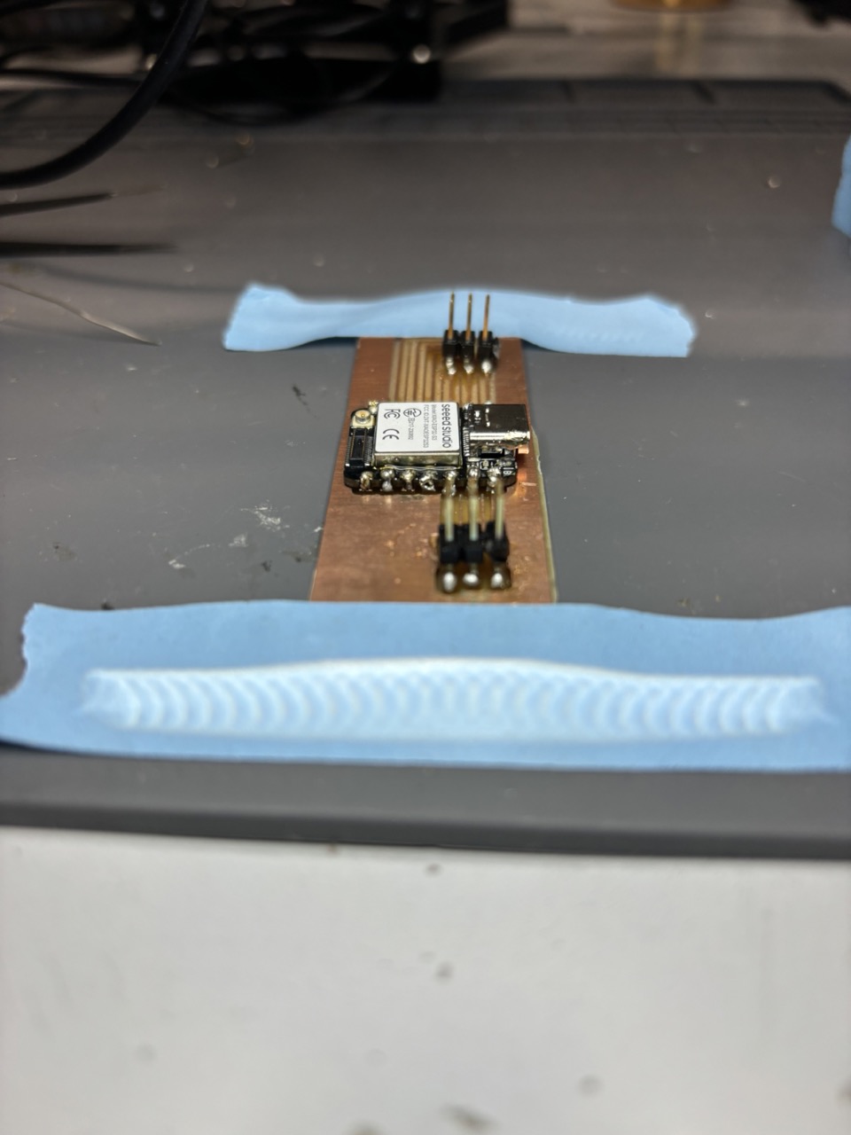
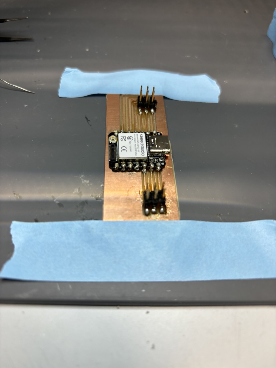
I tested my soldered board with a multimeter for continuity and made sure it was working with the week blink code, and all was well! If you would like to replicate this PCB, please use the following code:
/*
@version: v0.1.0

a basic starter design
*/

/* -- DECLARE_PCB -- */
const board = new PCB();

/* -- DECLARE_COMPONENTS -- */
const header_6 = footprint({"1":{"shape":"M -0.05,-0.025L 0.0517,-0.025L 0.0535,-0.0248L 0.0552,-0.0244L 0.056,-0.0243L 0.0578,-0.0237L 0.0593,-0.0232L 0.0602,-0.0229L 0.061,-0.0225L 0.0618,-0.0221L 0.0625,-0.0216L 0.0633,-0.0212L 0.064,-0.0208L 0.0654,-0.0197L 0.0661,-0.0191L 0.0668,-0.0186L 0.0686,-0.0168L 0.0691,-0.0161L 0.0697,-0.0154L 0.0708,-0.014L 0.0712,-0.0133L 0.0716,-0.0125L 0.0721,-0.0118L 0.0725,-0.011L 0.0729,-0.0102L 0.0732,-0.0093L 0.0737,-0.0078L 0.0743,-0.006L 0.0744,-0.0052L 0.0748,-0.0035L 0.075,-0.0017L 0.075,-0.0009L 0.075,0L 0.075,0.0009L 0.075,0.0017L 0.0748,0.0035L 0.0744,0.0052L 0.0743,0.006L 0.0737,0.0078L 0.0732,0.0093L 0.0729,0.0102L 0.0725,0.011L 0.0721,0.0118L 0.0716,0.0125L 0.0712,0.0133L 0.0708,0.014L 0.0697,0.0154L 0.0691,0.0161L 0.0686,0.0168L 0.0668,0.0186L 0.0661,0.0191L 0.0654,0.0197L 0.064,-0.0208L 0.0633,-0.0212L 0.0625,-0.0216L 0.0618,-0.0221L 0.061,-0.0225L 0.0602,-0.0229L 0.0593,-0.0232L 0.0578,-0.0237L 0.056,-0.0243L 0.0552,-0.0244L 0.0535,-0.0248L 0.0517,-0.025L 0.0509,-0.025L 0.05,-0.025L -0.05,-0.025","pos":[0.107,-0.1],"layers":["F.Cu","F.Mask"],"index":1},"2":{"shape":"M -0.05,0.025L 0.05,0.025L 0.05,-0.025L -0.05,-0.025L -0.05,0.025","pos":[-0.107,-0.1],"layers":["F.Cu","F.Mask"],"index":2},"3":{"shape":"M -0.05,0.025L 0.05,0.025L 0.05,-0.025L -0.05,-0.025L -0.05,0.025","pos":[0.107,0],"layers":["F.Cu","F.Mask"],"index":3},"4":{"shape":"M -0.05,0.025L 0.05,0.025L 0.05,-0.025L -0.05,-0.025L -0.05,0.025","pos":[-0.107,0],"layers":["F.Cu","F.Mask"],"index":4},"5":{"shape":"M -0.05,0.025L 0.05,0.025L 0.05,-0.025L -0.05,-0.025L -0.05,0.025","pos":[0.107,0.1],"layers":["F.Cu","F.Mask"],"index":5},"6":{"shape":"M -0.05,0.025L 0.05,0.025L 0.05,-0.025L -0.05,-0.025L -0.05,0.025","pos":[-0.107,0.1],"layers":["F.Cu","F.Mask"],"index":6}});
const pin_1 = pin(header_6, 1);
const pin_2 = pin(header_6, 2);
const pin_3 = pin(header_6, 3);
const pin_4 = pin(header_6, 4);
const pin_5 = pin(header_6, 5);
const pin_6 = pin(header_6, 6);

/* -- SET_POSITIONS -- */
pin_1.position.set(-1.27, 0);
pin_2.position.set(0, 0);
pin_3.position.set(1.27, 0);
pin_4.position.set(2.54, 0);
pin_5.position.set(3.81, 0);
pin_6.position.set(5.08, 0);

/* -- ADD_TRACE -- */
addTrace(pin_1, pin_2);
addTrace(pin_3, pin_4);
addTrace(pin_5, pin_6);

/* -- FINALIZE_PCB -- */
board.finalize();

/* -- EXPORT -- */
export(board, "starter_pcb_design");
I acknowledge the help and support of the MIT EECS staff, particularly Anthony Pennes, in thinking through the steps required to do this assignment simply, and ChatGPT 3.5, which helped me take text and images from the native OS X text editor I used to quickly document on my Mac into simple HTML for my git repo.
Updated June 8, 2024