Individual Assignment Prompt:
- design and 3D print an object (small, few cm3, limited by printer time)
that could not be made subtractively
- 3D scan an object (and optionally print it)
Part 1: Design and 3D Printing
Design and print something that can't be made subtractively.... okay now what does that mean? In my experience, with a nice enough 3-axis CNC machine, you can extract contours from just about in geometry, take some flip-cuts to achieve both the convex and concave portions, and glue all the pieces together. And if you had a 5-axis CNC you could skip the contours. flips, and glue altogether. The only thing that I can think of that can't be made subtractively would be where volumes nest within one another, where one volume blocks the subtractive device from reaching the other volume.
The first thing that came to mind when considering this were different sorts of joints, hinges, or chains--objects where layers link together. After catching the introductory lecture I was particularly interested in the fabrics. I thought this made for a curious additive use-case, since the entanglement of layers within a fabric prevent a subtractive process. I decided to aim for this--a structure made up of multiple independent layers, that are bound together by their entanglement.
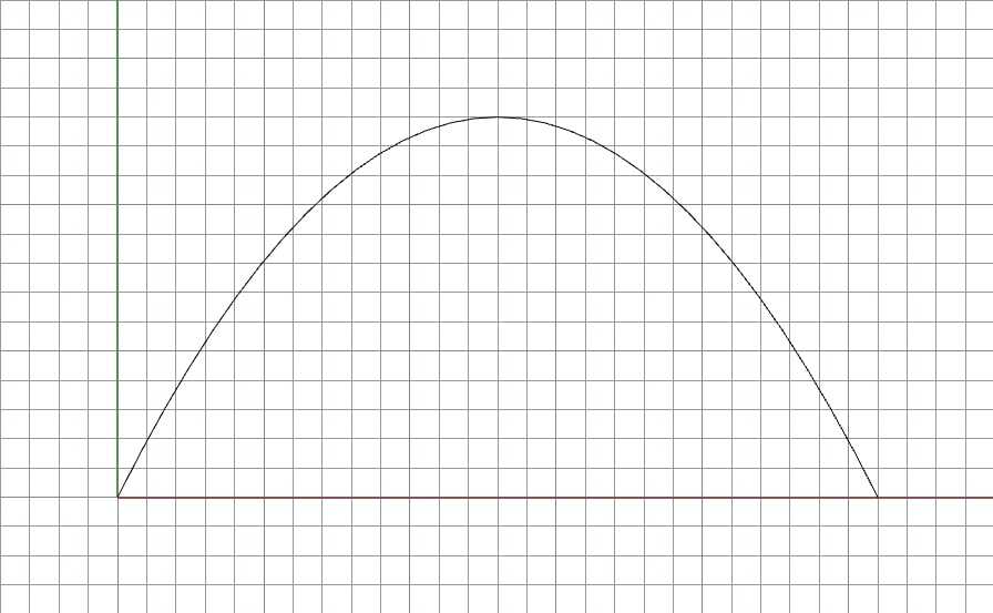
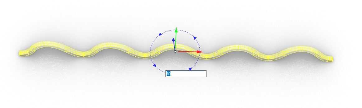
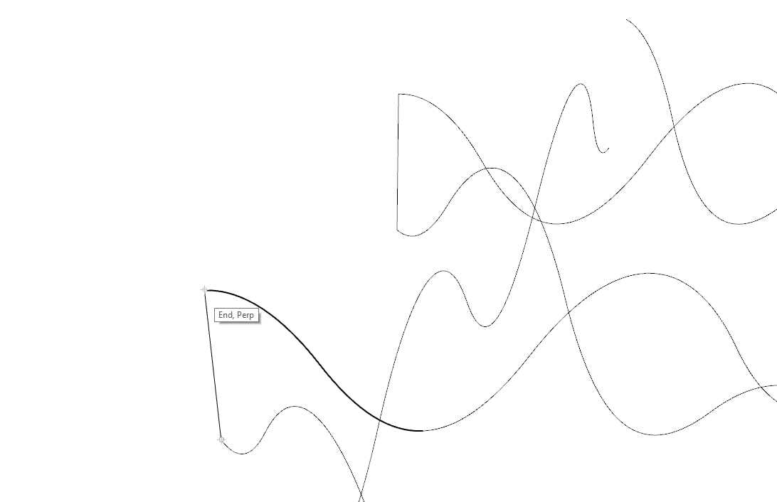
I knew that in order to have multiple layers woven together, I was going to need to design a print that could be made without support structure. This would just cause all the layers to lock together and would be very difficult if not impossible to remove with a basic PLA 3dprinter. So I wanted to work with a geometry that could gradually build upon itself. In architecture, the catenary arch--which is just a parabola--has the most efficient load distribution, so I decided to start with this.
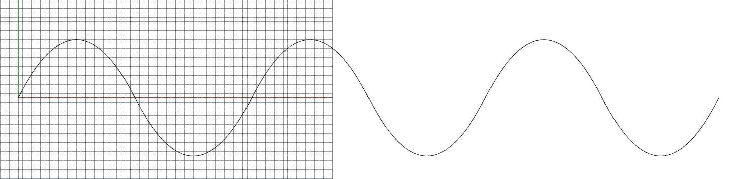
I placed this curve end to end to begin to produce what will become a thread in the fabric. It begins to read something like a Sine Curve.
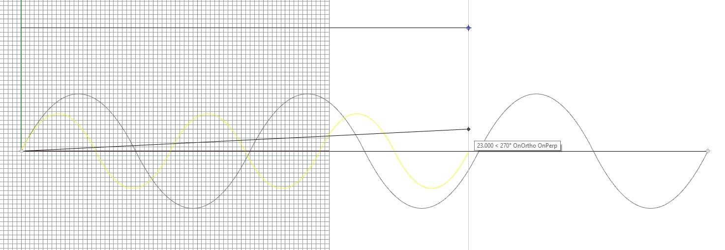
In order to dial in the amplitude of the curve I thought to start by scaling the length to a size that would fit on the printer bed.
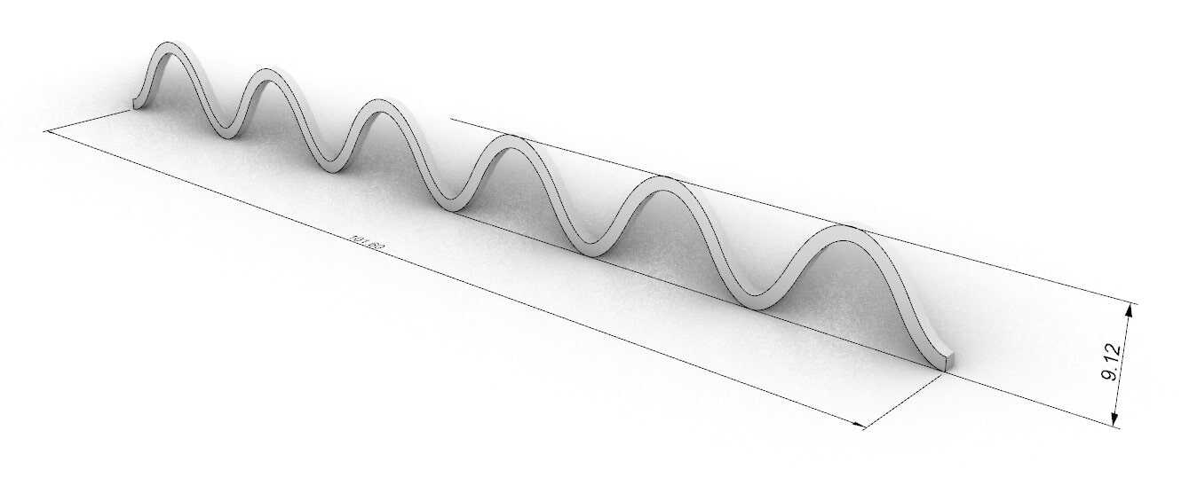
Once I got a tentative length/height, I had to figure out how thick I wanted to make the thread. The 3dprinter I was using had a .6mm nozzle, so I thought it was best to work in factors of .6mm. I simply doubled this value to use as an offset for the curve, and then extruded 1.2mm as well to extrude thickness.
I started to play around with how one thread might intersect others to produce one layer within this fabric.
In order to have it function like a fabric I needed to have additional layers that could mesh together. Unfortunately, in a grid pattern like this, while you do have the superimposition of two fabric layers, they don't actually lock together. One layer would simply lift off the other, so this wasn't quite working yet, back to the drawing board.

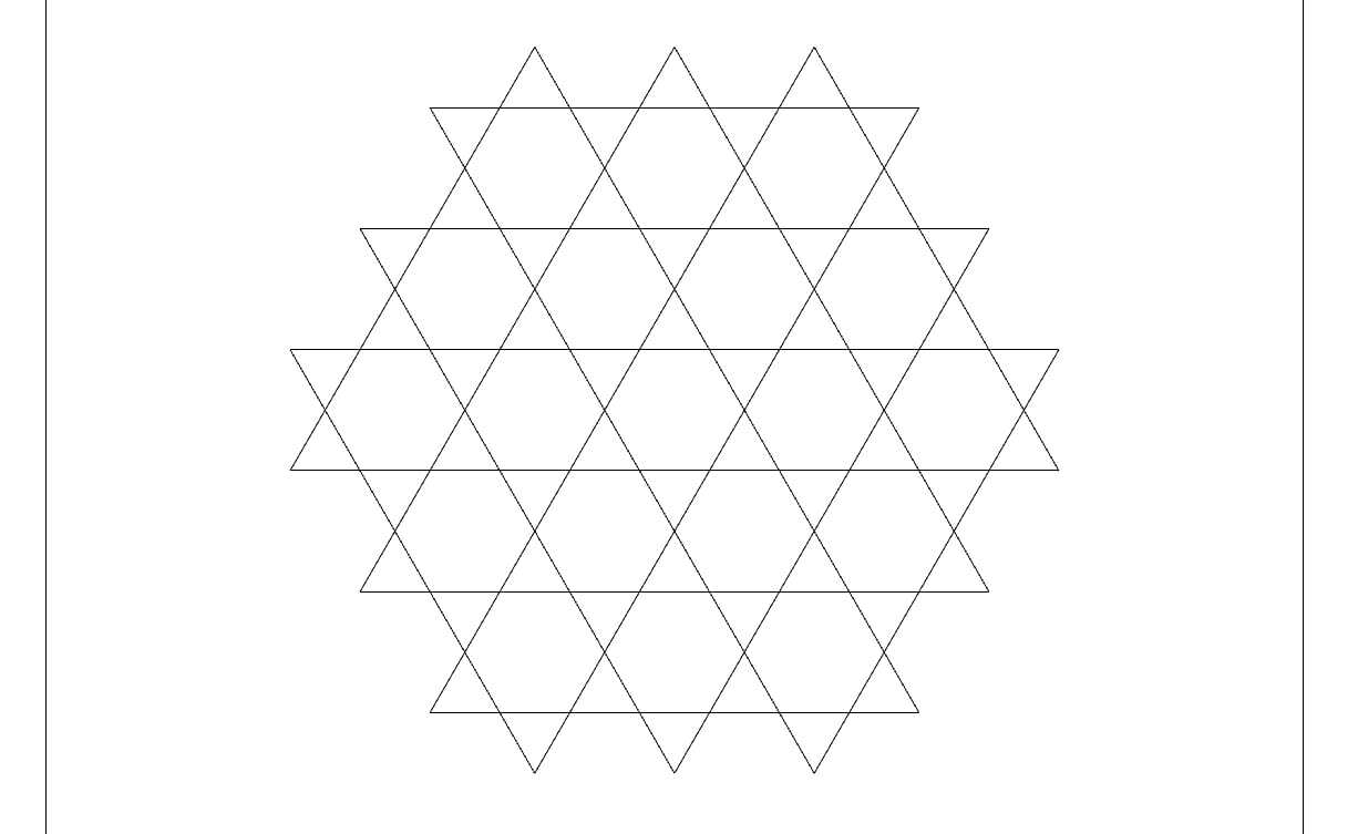
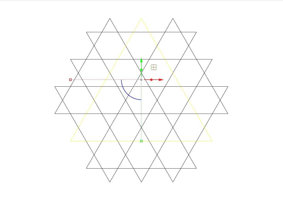
I figured since my first attempt didn't work I should take a glance at how weaving actually works and go from there. I decided to base this next attempt on a traditional chinese weaving practice that mixes together hexagons and triangles.
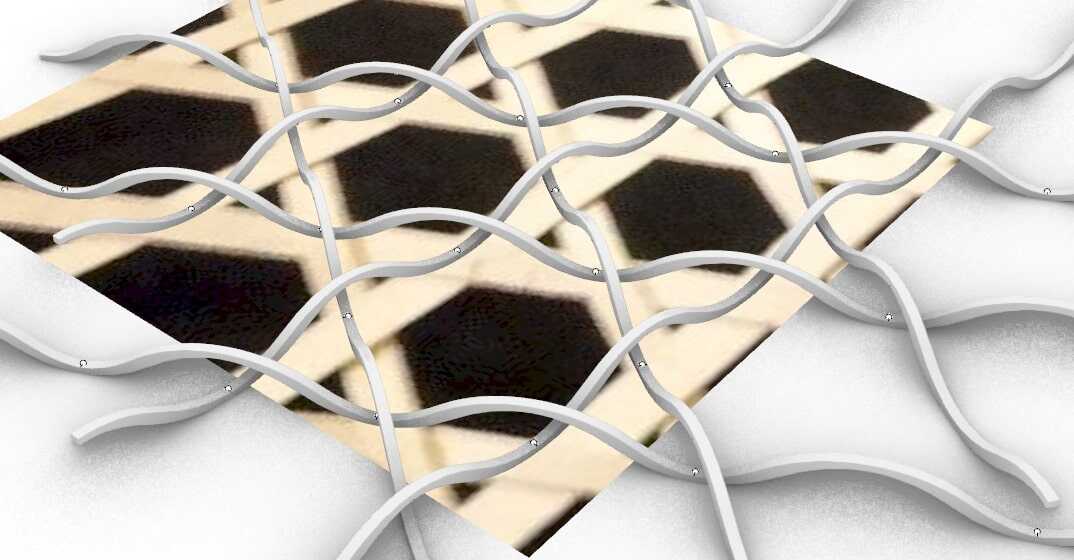
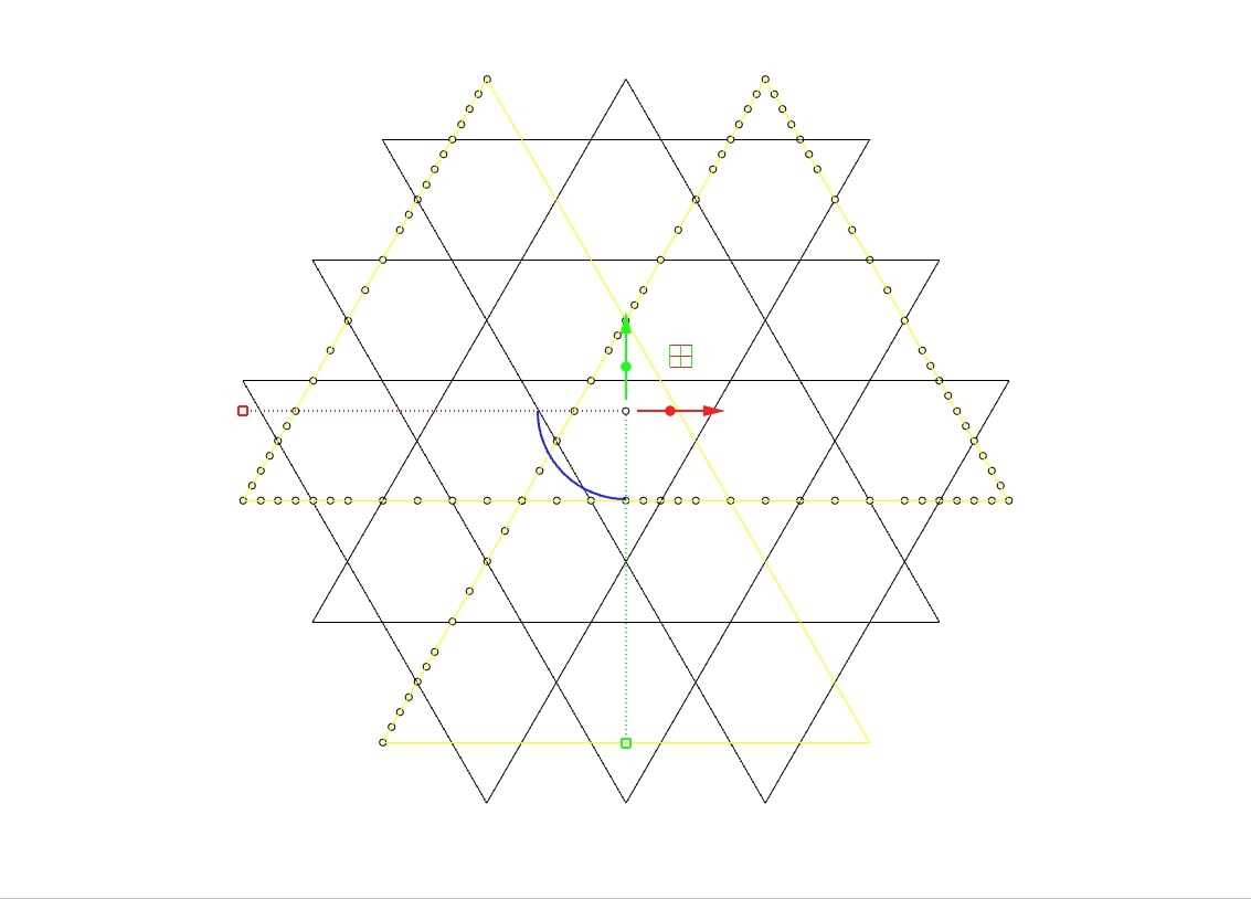
In order for the threads to remain unattached from their neighbors, I had to calibrate each apex and valley to be opposite one another when they reached an intersection. Can finally start seeing the emergence of a working fabric, even if it maybe looks a bit more like a plate of spaghetti.
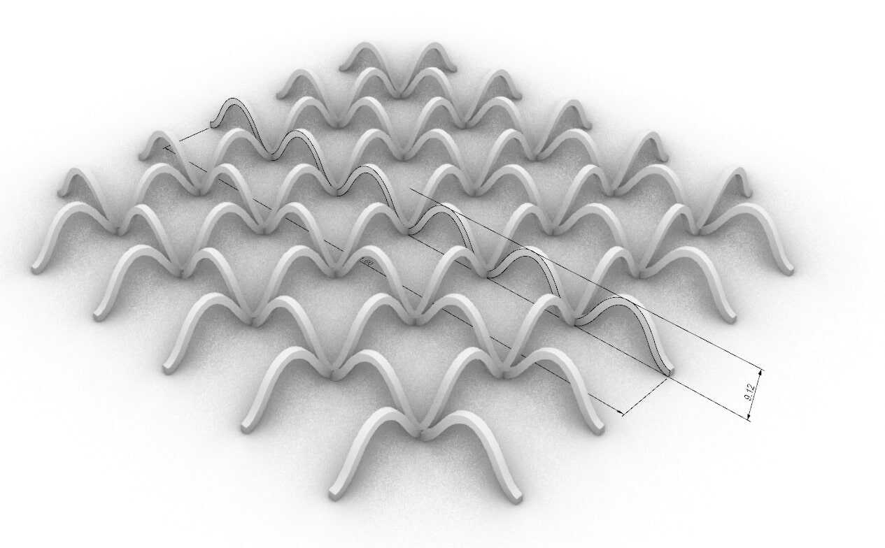
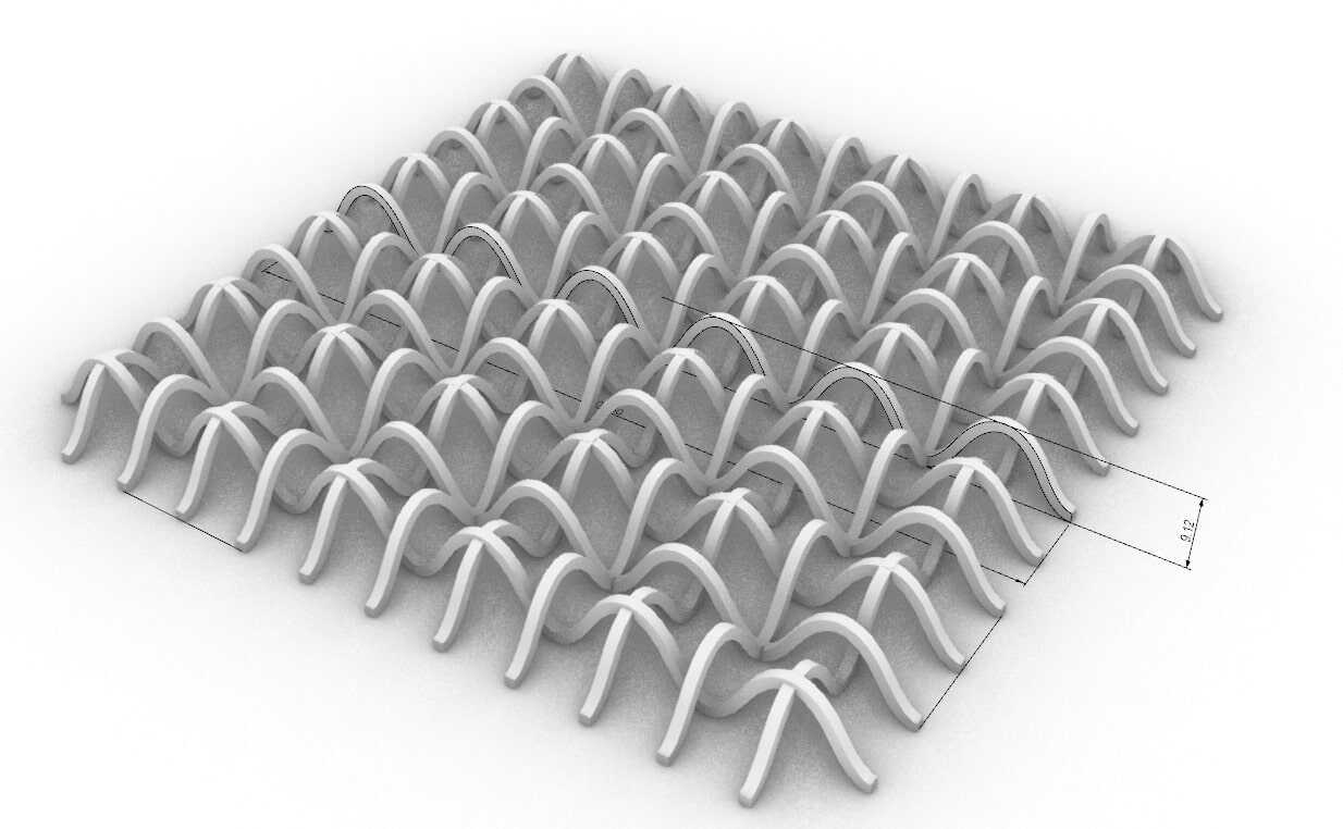
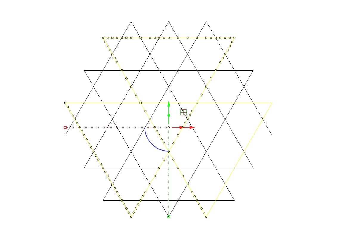
Theoretically, each of these threads could continue forever, but that isn't going to do me much good considering my printer bed is only 6x10". After figuring out how the technics were going to work, I started to lay out a scheme that looks complete. Due to the nature of the thread pattern, I could either make a hexagon or a triangle. I preferred the hexagon.
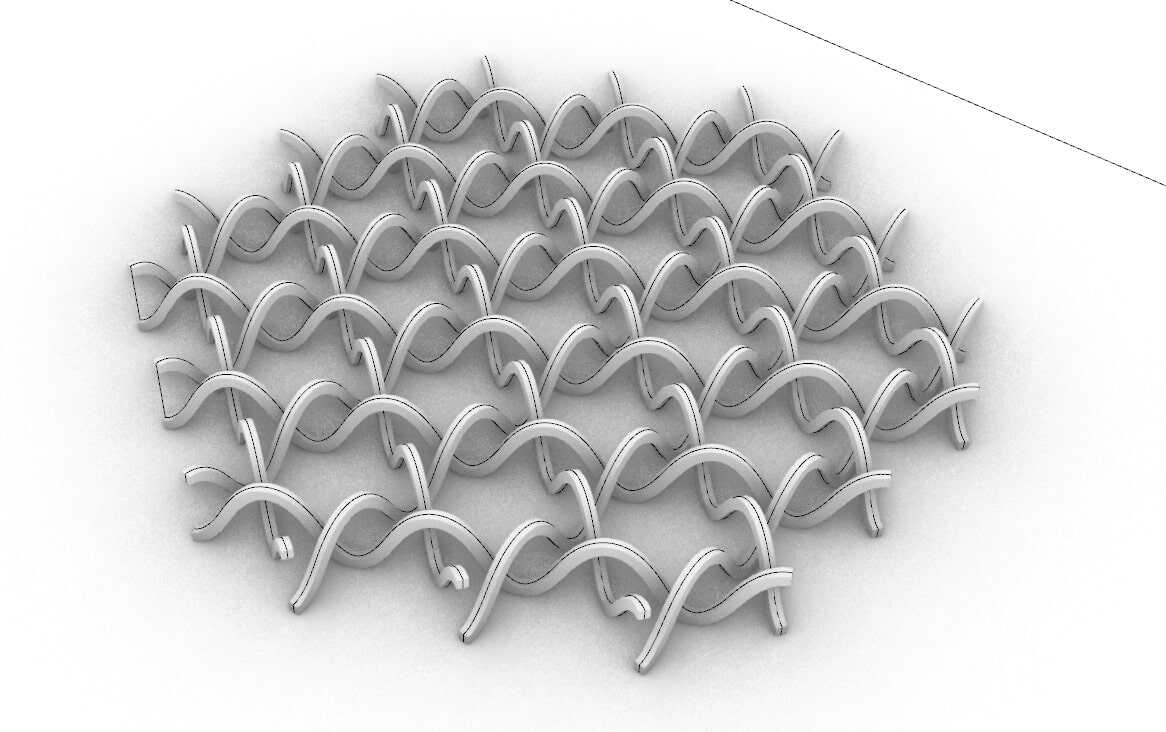
Because each thread is distant from one another and independent, upon printing they would very easily fall over and disassemble, as any weave not woven very tightly does. In order to prevent this unraveling, I tied each of the edge intersections together. This began to produce distinct layers within the fabric that were geometrically entangled within the each other layer.
Once printed, each of these should be an independent layer of geometry bound together like a fabric.
After figuring out the scheme, I reintroduced thread thickness.
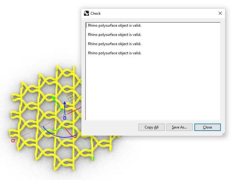
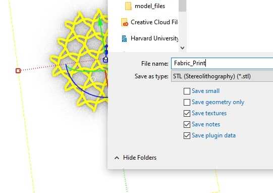
After using a Boolean Union command to merge all connecting geometries, I make sure to check each object for validity (which is necessary for being able to 3dprint)
Spaghetti! :D Time to print.
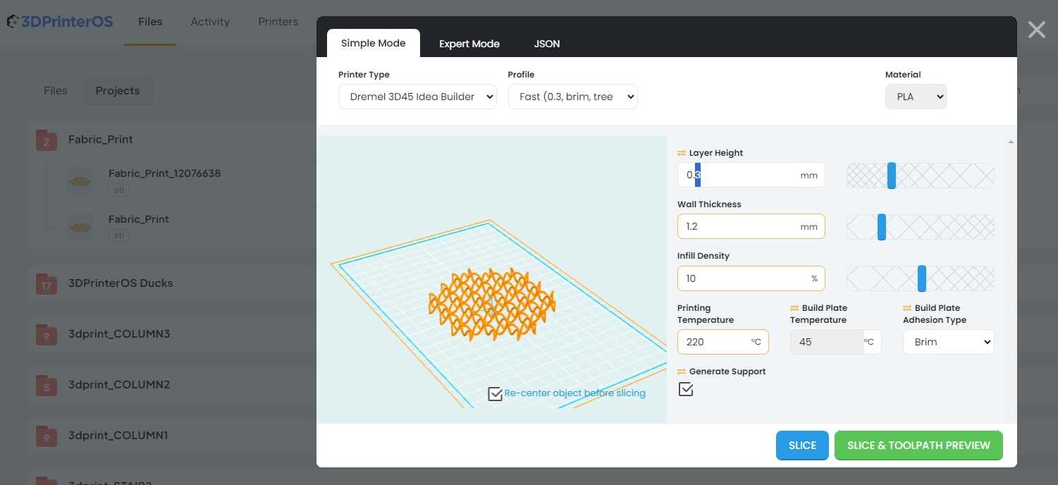
These are the units that my local print farm presets for 3dprinting. They are not what I want for this project. My thread is very thin so I want to have a much smaller layer height to increase density of the print. Wall thickness can be .6mm since the total thickness is 1.2mm, which make this a print with no infill. I also need to make sure I don't generate support.
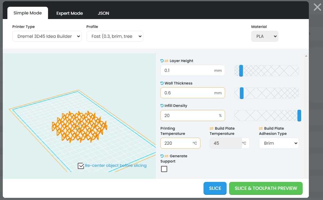
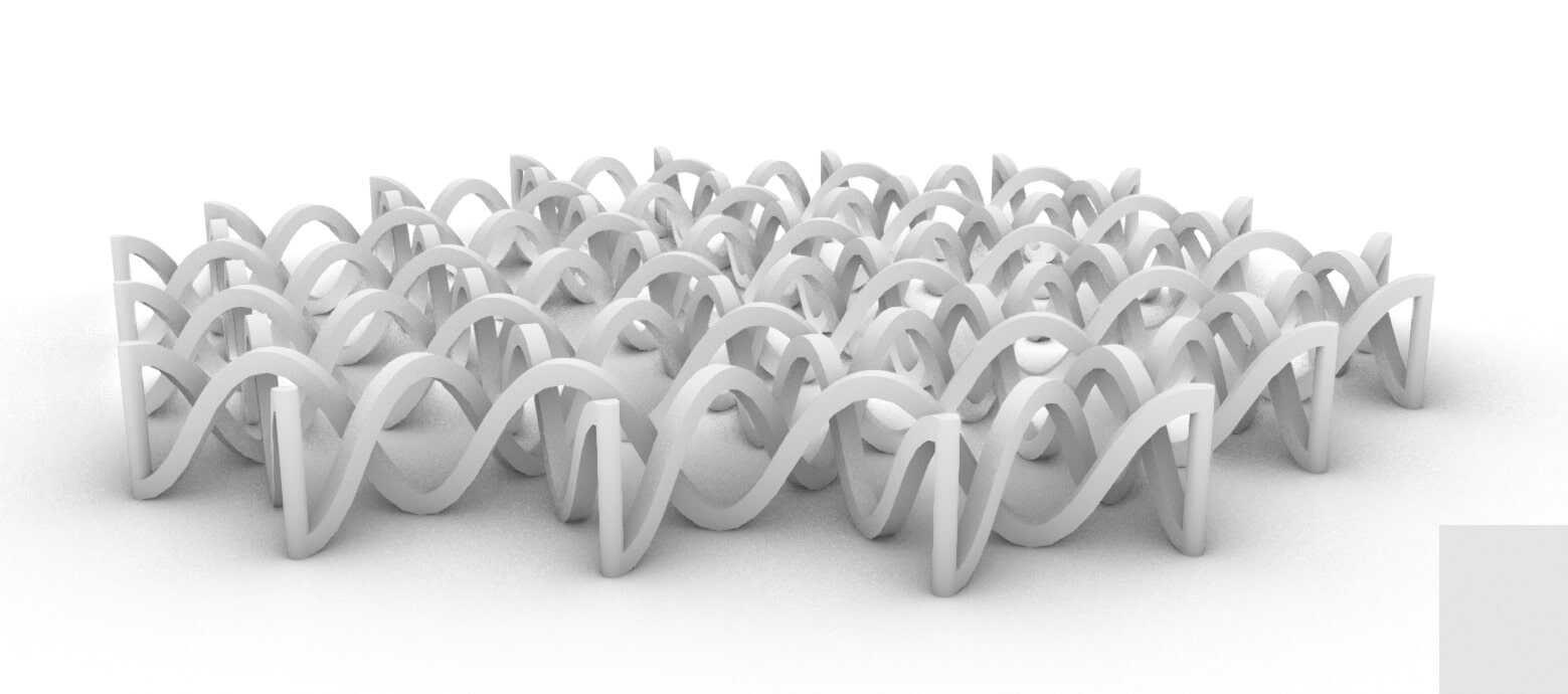
This is what I'm going to generate Gcode for.
Looks like what I'm going for! Fingers Crossed...
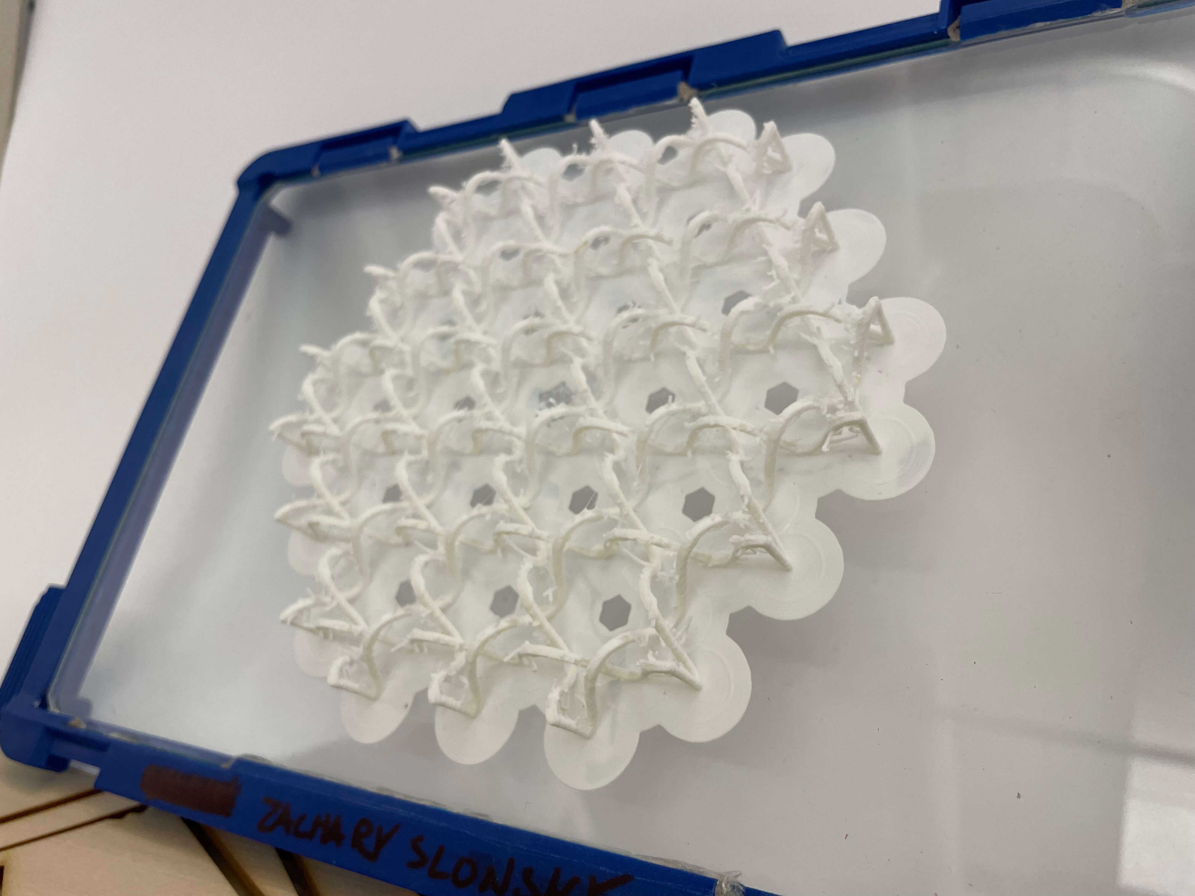
It printed! There are a lot of spikes extending off the threads which detract from the clarity of the geometry but happily don't disrupt the "fabrics" functionality
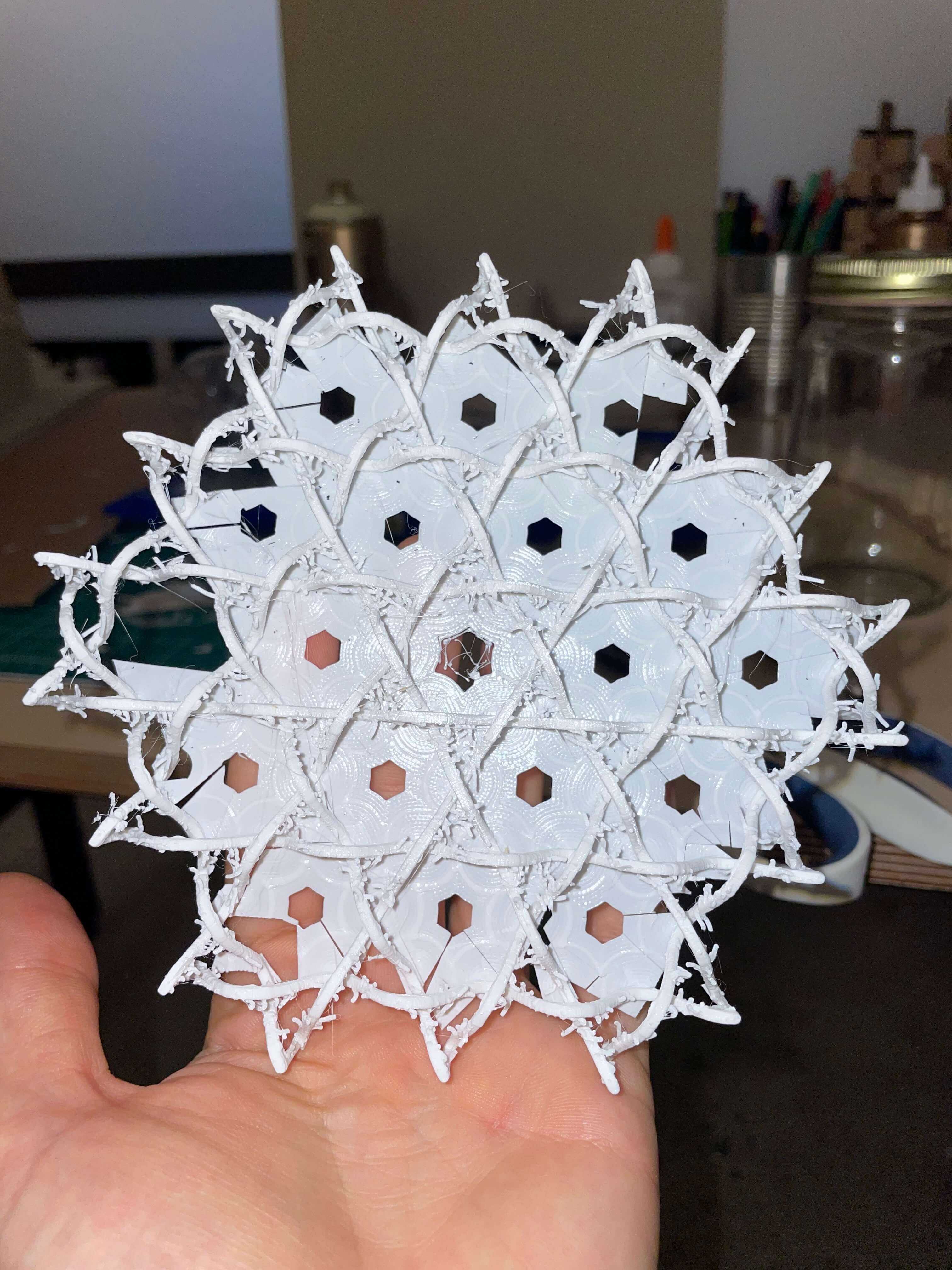
It was annoying and kind of difficult to cut off all the brim support, and I ended up getting a bit impatient because I had to catch a flight and ended up breaking one of the end-ties :/ but the show must go on!
Video illustrates the geometric independence of the interconnected layers.

Result: It works! Also looks a lot more like a snowflake than a fabric ^_^
Part 2: 3D Scanning
The task? To 3D scan an object. I had to catch a flight on Saturday and printing was pretty involved so all my Cambridge time was wrapped up before I could get to this part of the assignment. Lucky for me, 3D scanning is easy to do on the go!
I used my Iphone to collect photos, which is pretty easy and assessible. The harder part was definitely figuring out how to capture a room on an airplane without being suspected a domestic terrorist. For a brief moment it seemed all the flight attendents were at the front of the plane, and most everybody else was asleep. I took my chance. I decided to use reality capture as my host software to stitch together my photos and make a photogrammetry model. It's user interface is very beginner friendly, it basically tells you what to do. Add your images You can simply press "start" which Aligns your images, Calculates a 3D Model from them, and texturizes the mesh, or you can do these steps one at a time. Here's the model of the flight attendent's backroom prior to it being texturized. It looks pretty cool and also pretty incomplete, lots of large triangle abberations, and definitely not a completely enclosed room like I was intending. Texturing makes a .mtl and .png file. The .mtl tells your 3d Model, oftentimes exported as a .obj, how to read the png it creates. The png is essentially a collage of each triangular surface within the mesh. Definitely some areas of the model that could be fixed by adding more photos, but I was off the plane by the time I had arrived at this model. Se la vie. Hoping this homework assignment didn't put me on some watchlist.


