Final Project
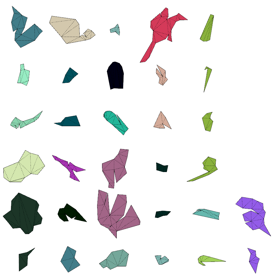
A program unfolds mesh object, cut into parts, and nest parts into machine bed size.
MeshUnfold
Introduction and Brainstorming | April 1, 2020
What is the optimal selection of mesh edges to be cut for fast fabrication and easy assembly?
This project aims to develop a program that provides an easy solution to make an object bigger than fabrication machine's print bed size, 3D printer, vinyl cutter, and laser cutter, by converting inputted 3D mesh into ready-to-print grouped 2D polygons. As a result output, the program provides an optimized 2d layout of polygons that can maximize the usage of the material for laser cutting and minimize operation time for 3D printing.
Commercial 3D printer software provides layer slicing functions that convert 3d shapes to multiple layered machine paths to print the object. The machine often allows for size re-scaling of the inputted form to adjust to the machine bed size. However, if a user wants to make a shape that has a bigger volume than the print bed size, width, length, and height, the user should do this process in other 3D softwares, such as Fusion and Rhino, to split the whole model into several parts.
Many commercial programs have existing functions for creating a mesh and unfolding or nesting 2d polygons. However, by making this from scratch, I am looking forward to learning 3D computational geometry and finding the optimal solution.
Problems to solve
Converting mesh to series of polygons
Parameters to select mesh for splitting 2D polygons
Nesting polygons in rectangles
...
Input parameters
Machine width and height
Minimum and maximum size of single piece
...
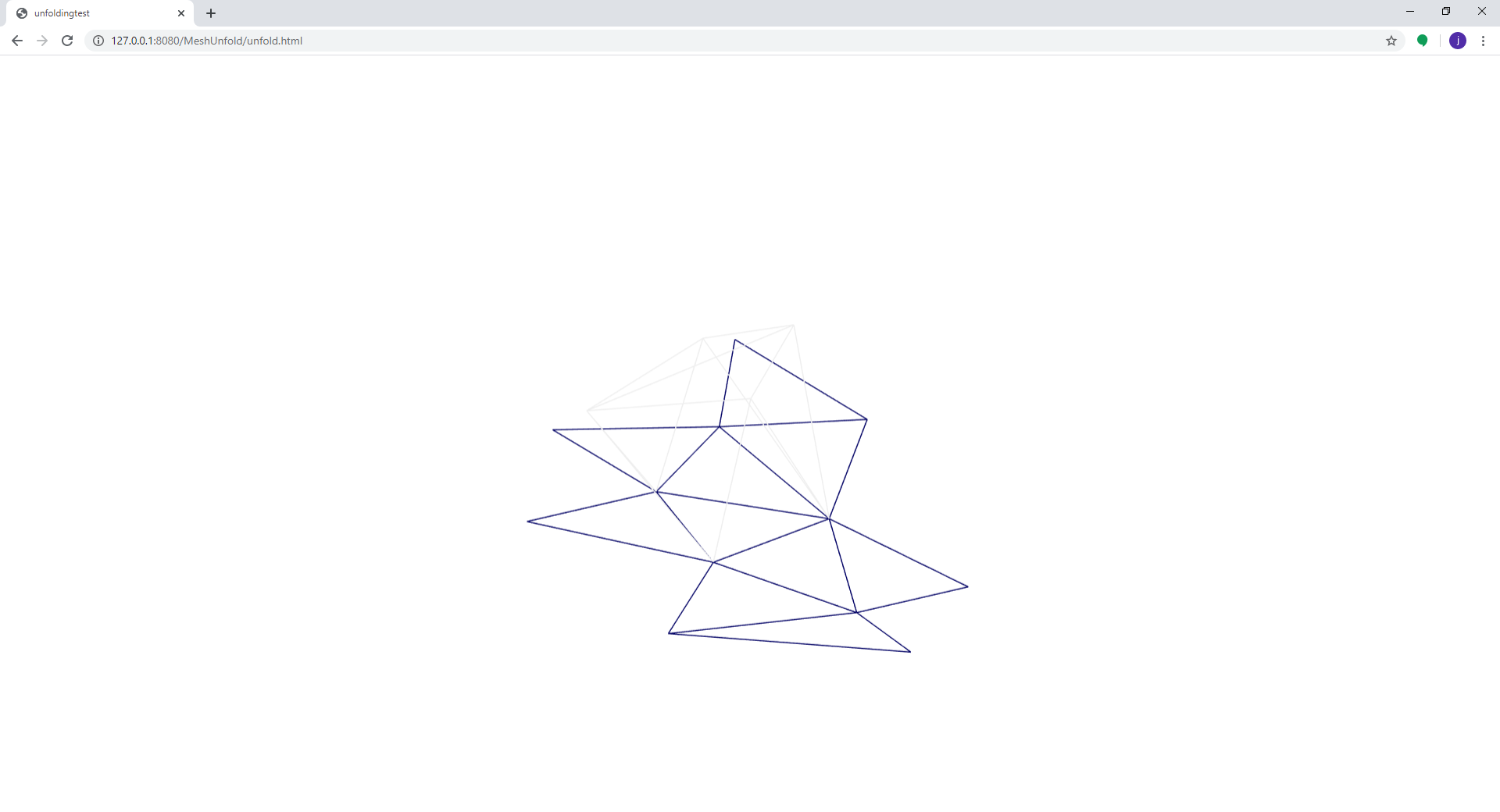
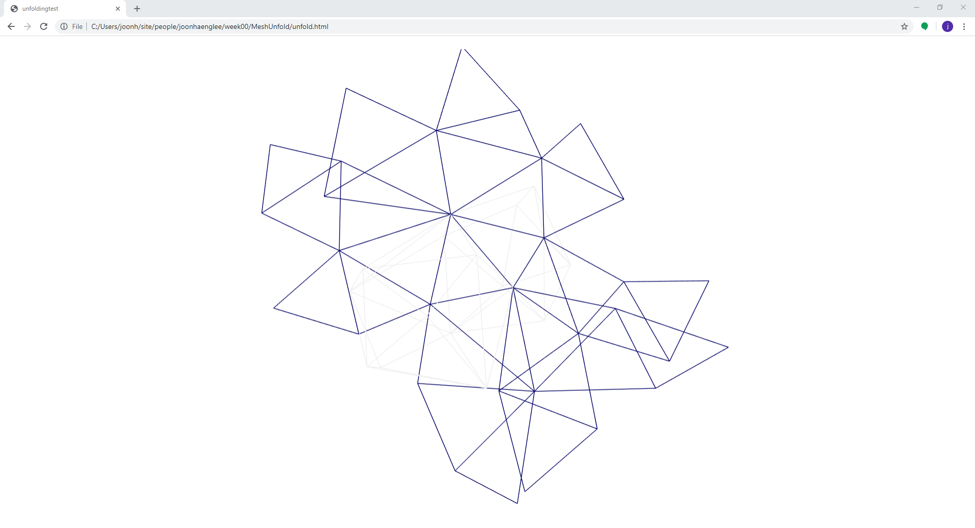
Sample test using Grasshopper and Ivy plug-in.
Import mesh > Create mesh graph > Find minimum spanning tree > Cut and unroll
Files
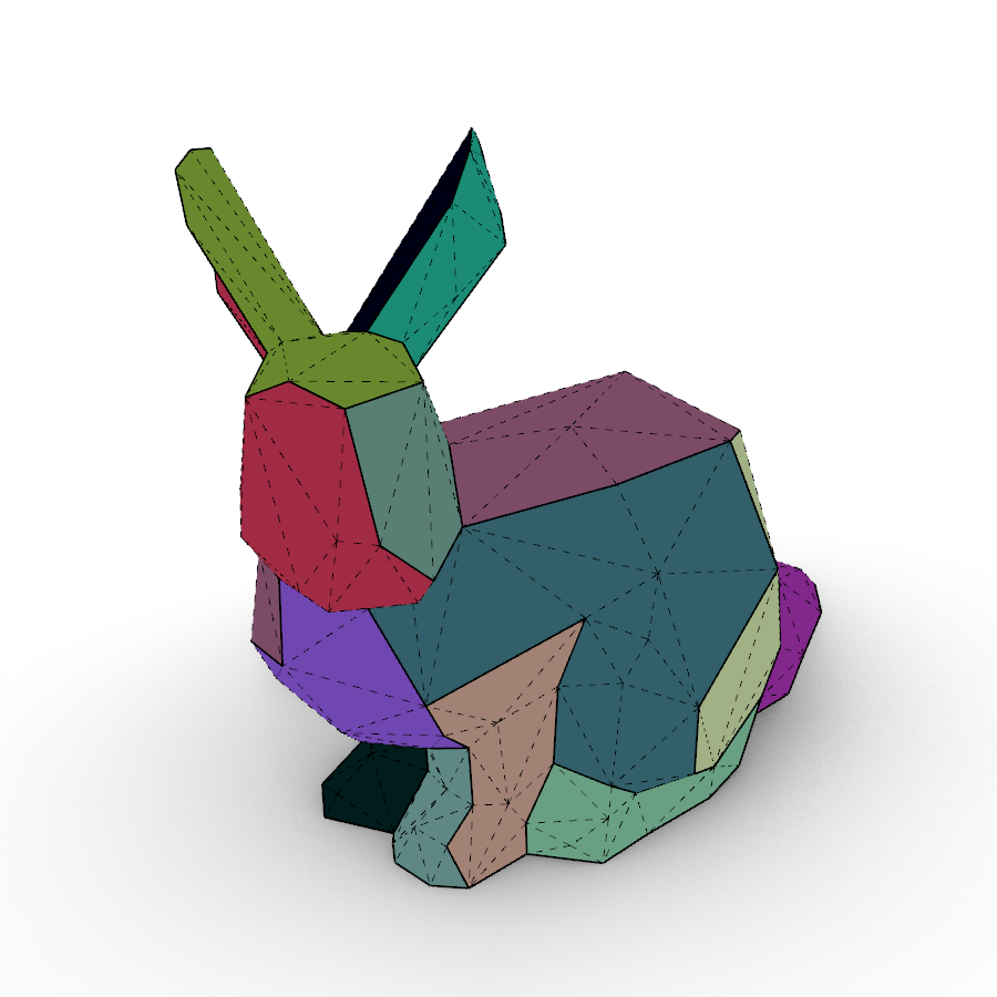
Stanford Bunny 309 faces
References
Ivy - Grasshopper plugin for mesh unroll
Algorithm for 2D irregular-shaped nesting problem based on the NFP algorithm and lowest-gravity-center principle
 SVGnest- A browser-based nesting tool
Multiple Elements and Text
Qestion Set Up | April, 2020
Big Question:
Assume that you are making polyhedron object with flat sheet material. Polygons can be grouped(routed), then unfolded to make a machining path. To fold gourped polygons, you must make a score line on the material using machine.
Is way of grouping and routing optimize fabrication process by reducing machining hours, manual folding and assembly hours, and material to be used ?
It is necessary to cut out some portion of flat and stiff material to fold. The below image shows sections of the folded material and cut pattern on the material before the fold.
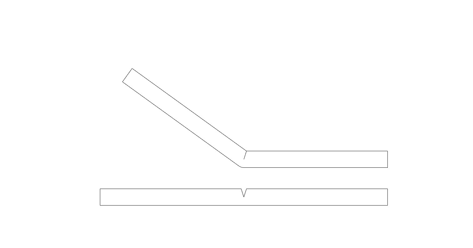
When the desired shape has both convex and concave zones, a cutting pattern should be placed on both sides of the material. This problem could be solved by simply scoring one side of the material, then flip the sheet and score the other. However, this additional process might lead to fabrication errors or a more complex manufacturing process.
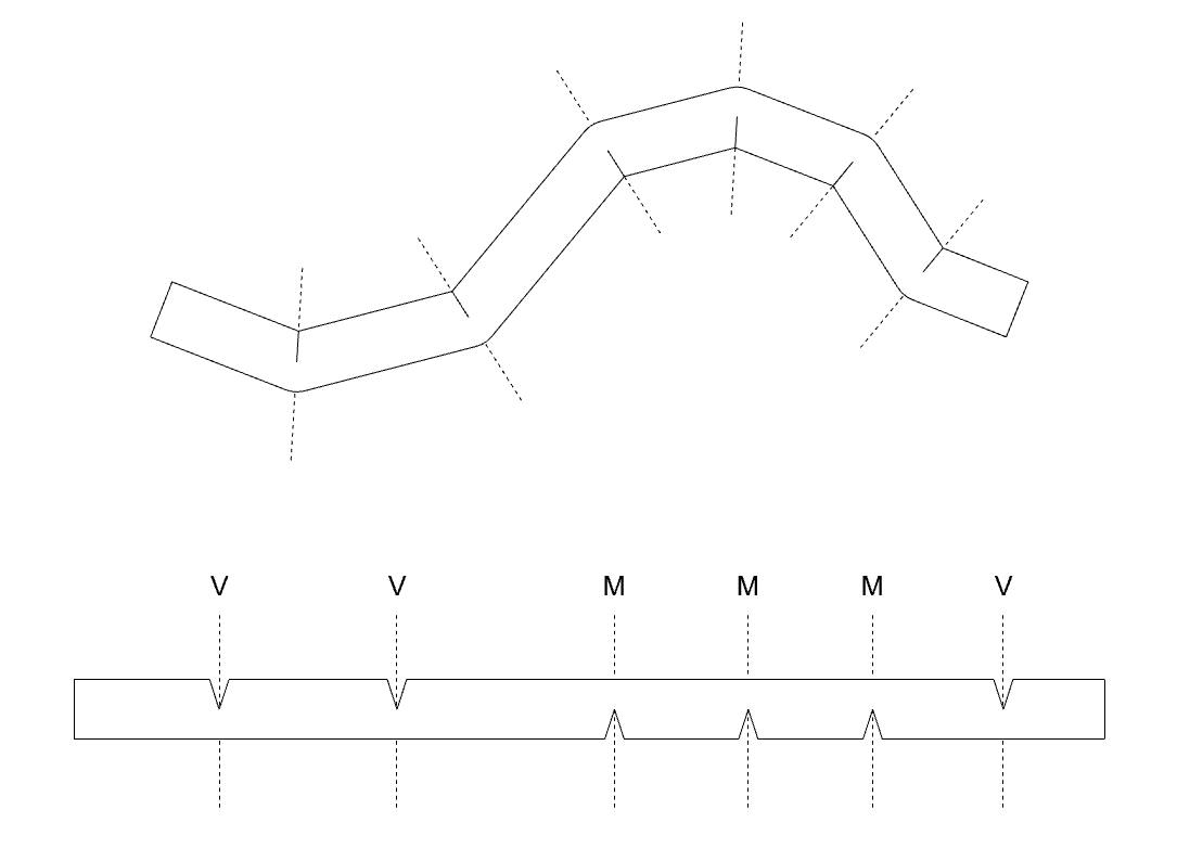
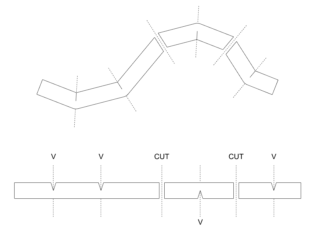
Is this problem can be solved by finding folding lines to cut, and make small pieces that only have one type of foldings?
To answer those questions, I studied mesh representation and a way to manipulate mesh data.
First small step question:
- How to represent polyhedron and unfold it?
Process | May, 2020
Importing Mesh
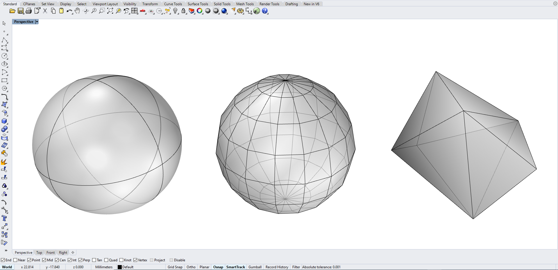
I created sample obj file from Rhino by drawing shpere and converted nurbs sphere into Mesh. It was possible to control number of out put faces, so I reduced number of faces into 10 to test with. All of mesh faces are set as triangle.
After exporting obj file, I tried to understand what obj file is. Wikipidea explanation helped me to understand the structure of the objfile.
    # List of geometric vertices, with (x, y, z [,w]) coordinates,
    # w is optional and defaults to 1.0.
    v 0.123 0.234 0.345 1.0

    # List of texture coordinates, in (u, [,v ,w]) coordinates,
    # these will vary between 0 and 1. v, w are optional and default to 0.
    vt 0.500 1 [0]

    # List of vertex normals in (x,y,z) form; normals might not be unit vectors.
    vn 0.707 0.000 0.707

    # Polygonal face element
    f v1/vt1/vn1 v2/vt2/vn2 v3/vt3/vn3 ...
Obj file in text :
    # Rhino

    mtllib MeshSample.mtl
    usemtl diffuse_Black
    v -2.5813407897949219 -2.1889743804931641 -0.38196274638175964
    v 0.65565627813339233 -2.1691322326660156 -2.2487366199493408
    v 0.50404548645019531 -1.6038597822189331 0.99214035272598267
    v -2.7688426971435547 0.62733733654022217 1.3206555843353271
    v -3.1897687911987305 0.46314927935600281 -2.3820698261260986
    v 0.60596787929534912 1.9520754814147949 0.06672561913728714
    v 0.50404548645019531 -1.6038597822189331 0.99214035272598267 // == V2
    v -2.7688426971435547 0.62733733654022217 1.3206555843353271  // == V3
    v -0.37693735957145691 2.1796708106994629 -2.1620137691497803
    v -2.7688426971435547 0.62733733654022217 1.3206555843353271 // == V3
    v -3.1897687911987305 0.46314927935600281 -2.3820698261260986 // == V4
    v -0.37693735957145691 2.1796708106994629 -2.1620137691497803  // == V9
    v 0.65565627813339233 -2.1691322326660156 -2.2487366199493408 // == V1
    vt 0.31169196963310242 0.17309394478797913
    vt -0.099096514284610748 0.098736271262168884
    vt 0.23367762565612793 -0.32448849081993103
    vt 0.41290870308876038 0.5746234655380249
    vt 0.15371593832969666 0.56317311525344849
    vt 0.69271504878997803 0.76106297969818115
    vt 0.63955128192901611 0.29132026433944702
    vt 0.44271016120910645 1.1669238805770874
    vt 0.92515802383422852 0.81010866165161133
    vt 1.2472586631774902 1.3133976459503174
    vt 1.3018485307693481 0.87406229972839355
    vt -0.014250267297029495 0.80088096857070923
    vt 0.87300461530685425 0.23866783082485199
    vn -0.54257309436798096 -0.82861989736557007 0.13785308599472046
    vn 0.42445772886276245 -0.69712340831756592 -0.57780152559280396
    vn 0.42814129590988159 -0.8071170449256897 0.40651822090148926
    vn -0.58940553665161133 0.17791260778903961 0.78800266981124878
    vn -0.76695841550827026 0.12049369513988495 -0.63028252124786377
    vn 0.63934534788131714 0.70599061250686646 0.30465510487556458
    vn 0.55640292167663574 -0.53655987977981567 0.63444411754608154
    vn -0.35942506790161133 0.65748864412307739 0.66221016645431519
    vn 0.29038766026496887 0.81019431352615356 -0.50917595624923706
    vn -0.51344358921051025 0.69635790586471558 0.50145930051803589
    vn -0.60318517684936523 0.62943673133850098 -0.48987448215484619
    vn 0.19642183184623718 0.73492246866226196 -0.6490820050239563
    vn 0.64330857992172241 -0.61853975057601929 -0.45117923617362976
    f 1/1/1 2/2/2 3/3/3
    f 4/4/4 5/5/5 1/1/1
    f 6/6/6 4/4/4 7/7/7
    f 8/8/8 6/6/6 9/9/9
    f 10/10/10 9/9/9 11/11/11
    f 12/12/12 2/2/2 5/5/5
    f 5/5/5 2/2/2 1/1/1
    f 4/4/4 1/1/1 7/7/7
    f 6/6/6 7/7/7 13/13/13
    f 9/9/9 6/6/6 13/13/13
Convert text file into face vertex list :
The first face is made by three vertices no.1,2, and 3, and the second face is made by three vertices no.4,5,1. So, I represent each faces with nine digits on the list. Then, using some code, I made an array with all vertex coordinates corresponding to mesh faces.
    var face = new Float32Array([
        -2.581341,0.381963,-2.188974, // Vertex 1 XYZ
        0.655656,2.248737,-2.169132, // Vertex 2 XYZ
        0.504045,-0.99214,-1.60386 // Vertex 3 XYZ
        )]
    var MeshSample_1 = new Float32Array([
        -1.559738,-0.303075,-2.083298,1.677259,1.563699,-2.063456,1.525648,-1.677178,-1.498184,
        -1.74724,-2.005693,0.733014,-2.168166,1.697032,0.568825,-1.559738,-0.303075,-2.083298,
        1.627571,-0.751763,2.057752,-1.74724,-2.005693,0.733014,1.525648,-1.677178,-1.498184,
        -1.74724,-2.005693,0.733014,1.627571,-0.751763,2.057752,0.644665,1.476976,2.285347,
        -1.74724,-2.005693,0.733014,0.644665,1.476976,2.285347,-2.168166,1.697032,0.568825,
        0.644665,1.476976,2.285347,1.677259,1.563699,-2.063456,-2.168166,1.697032,0.568825,
        -2.168166,1.697032,0.568825,1.677259,1.563699,-2.063456,-1.559738,-0.303075,-2.083298,
        -1.74724,-2.005693,0.733014,-1.559738,-0.303075,-2.083298,1.525648,-1.677178,-1.498184,
        1.627571,-0.751763,2.057752,1.525648,-1.677178,-1.498184,1.677259,1.563699,-2.063456,
        0.644665,1.476976,2.285347,1.627571,-0.751763,2.057752,1.677259,1.563699,-2.063456
        ]);
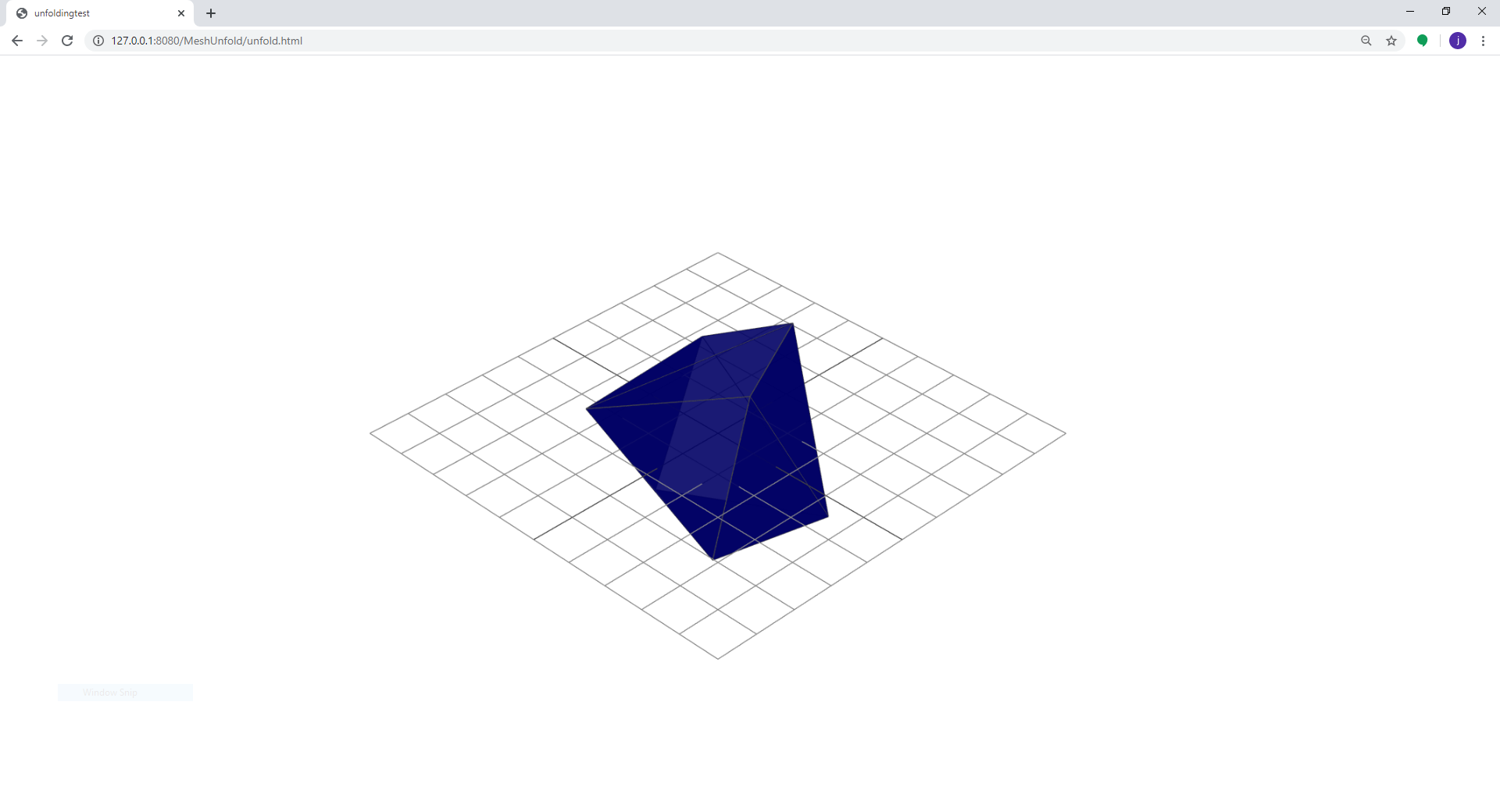
Visualization of Mesh using Javascript :
The array was used as input variable to create mesh in web environment.
Compute mesh properties
My goal is unfold the polyhedron.
To do that, I need a list of angles between mesh faces
To do that, I need a list of adjacent faces per each face.
To calculate angle between faces, I need face normal vectors to do dot product.
To do that, I need 3 vertices to do cross product.
To do that, I need a list of vertices and face list of vertices index.
So, I get needed lists one by one. Here are the reslut of sample 10 faces polyhedron.

    vertexList = [
        [-1.559738039970398, -0.30307498574256897, -2.0832979679107666],
        [1.6772589683532715, 1.5636990070343018, -2.0634560585021973],
        [1.5256479978561401, -1.6771780252456665, -1.4981839656829834],
        [-1.7472399473190308, -2.005692958831787, 0.7330139875411987],
        [-2.168165922164917, 1.6970319747924805, 0.5688250064849854],
        [1.6275709867477417, -0.7517629861831665, 2.0577518939971924],
        [0.644665002822876, 1.4769760370254517, 2.2853469848632812]
        ]
    faceList = [
        [0, 1, 2],
        [3, 4, 0],
        [5, 3, 2],
        [3, 5, 6],
        [3, 6, 4],
        [6, 1, 4],
        [4, 1, 0],
        [3, 0, 2],
        [5, 2, 1],
        [6, 5, 1],
        ]
    faceCenterList = [
        [0.5477229754130045, -0.13885133465131125, -1.8816459973653157],
        [-1.8250479698181152, -0.20391198992729187, -0.26048632462819415],
        [0.4686596790949504, -1.4782113234202068, 0.43086063861846924],
        [0.17499868075052896, -0.42682663599650067, 1.6920376221338909],
        [-1.0902469555536907, 0.38943835099538165, 1.1957286596298218],
        [0.05125268300374349, 1.5792356729507446, 0.26357197761535645],
        [-0.6835483312606812, 0.985885332028071, -1.1926430066426594],
        [-0.5937766631444296, -1.3286486566066742, -0.9494893153508505],
        [1.6101593176523845, -0.28841400146484375, -0.5012960433959961],
        [1.3164983193079631, 0.7629706859588623, 0.7598809401194254]
        ]
    faceNormalList = [
        [0.10732642824782597, -0.17570339453724929, -0.978575165711685],
        [-0.9835679726350891, -0.11787573564831808, -0.13674558183674032],
        [0.25541569741116493, -0.9374244965604681, 0.2366392502614921],
        [-0.28426152415731226, -0.22064112502289498, 0.9330127972500661],
        [-0.5220191265254702, -0.02153379510948092, 0.8526619067425072],
        [0.05757415980255939, 0.9977767291928138, 0.033568062266381656],
        [-0.39328540068367557, 0.6884366003629525, -0.6094108965958693],
        [-0.26675406561676607, -0.816793521426208, -0.5115570465090877],
        [0.9986516463062406, -0.04946506518567343, -0.015751084280541287],
        [0.9004346088340494, 0.3745088477650572, 0.22127050901455828]
        ]
    faceAdjacentList = [
        [6, 8, 7],
        [4, 6, 7],
        [3, 7, 8],
        [2, 9, 4],
        [3, 5, 1],
        [9, 6, 4],
        [5, 0, 1],
        [1, 0, 2],
        [2, 0, 9],
        [3, 8, 5]
        ]
    faceAngleList = [
        [2.0188185533233134, 1.702462942089455, 2.2337919986082024],
        [1.9816388231158957, 1.9703499911007138, 2.013743486100381],
        [1.9337285667066895, 2.1852284516704996, 1.873093235381627],
        [1.9337285667066895, 1.4382659488795524, 2.8198495812015745],
        [2.8198495812015745, 1.5478757956769436, 1.9816388231158957],
        [2.018554283810974, 2.2702584457312405, 1.5478757956769436],
        [2.2702584457312405, 2.0188185533233134, 1.9703499911007138],
        [2.013743486100381, 2.2337919986082024, 2.1852284516704996],
        [1.873093235381627, 1.702462942089455, 2.640816416182997],
        [1.4382659488795524, 2.640816416182997, 2.018554283810974]
        ]
Translate, Rotate, and Translate

    edgeVectorList = [

        [
            [0.8662572605993915, 0.49956997828012345, 0.005309920906670762],
            [-0.04603623354760884, -0.9840829556588391, 0.17164323925664296],
            [-0.9000948454319609, 0.4008649315793213, -0.17069439316134663]
        ],
        [
            [-0.11284307448558513, 0.9926374005252957, -0.044016265391609834],
            [0.18016626900822189, -0.5922670857838293, -0.7853405723689483],
            [-0.05688231661820419, -0.5165219703340375, 0.8543824999485828]
        ],
        ...
        ...
        ...
        ]
Unfolding
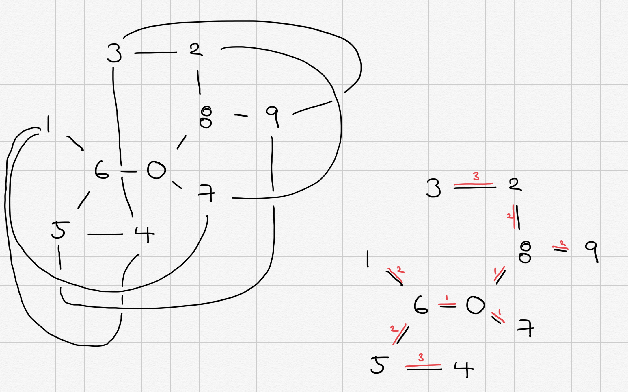
    foldGraph = [
        [0, 6, 5, 4],
        [0, 6, 1],
        [0, 8, 2, 3],
        [0, 8, 9],
        [0, 7]
        ]
    faceTypeList = [
        [0, 0, 0],
        [0, 0, 0],
        [0, 0, 0],
        [0, 0, 0],
        [0, 0, 0],
        [0, 0, 0],
        [0, 0, 0],
        [0, 0, 0],
        [0, 0, 0],
        [0, 0, 0]
        ]
0 : not moving,
1 : Rotate XX degree along shared edge between face 1,6
////Rotate XX degree along shared edge between face 6,0
2 : Rotate XX degree along shared edge between face 2,8
////Rotate XX degree along shared edge between face 8,0
...