As part of my final project, I am working on an automated milk scanner, that will be able to dispense milk or ink (liquids) at an automatic process.
Therefore, for this week, I wanted to work on a closed-loop feedback system for controlling how much milk is dispensed into the container as 3D scanning is being conducted.
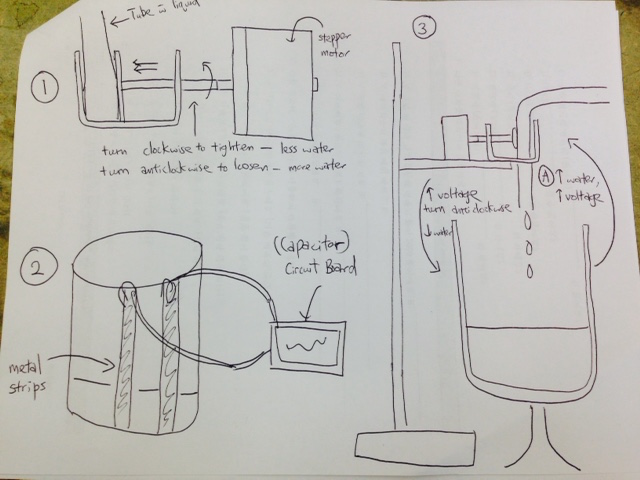
The logical system is one that we can vary the amount of milk that is being poured in at a controlled and measured flow.
Therefore, as more milk is poured in, I wanted to create a feedback loop to the structure to reduce the amount of milk poured in.
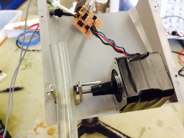
There are two parts to the feedback loop. The first part will be to use a stepper motor and to connect it to a water pipe. To reduce the flow of milk,
the stepper motor should turn clockwise, hence tightening the water pipe, and reducing the flow of milk. Similarly, to increase the flow of milk,
the stepper motor should turn anti-clockwise, loosening the grip and allowing more milk to flow through.
From the picture, you can see the mechanism that will tighten or loosen the grip to the water pipe.
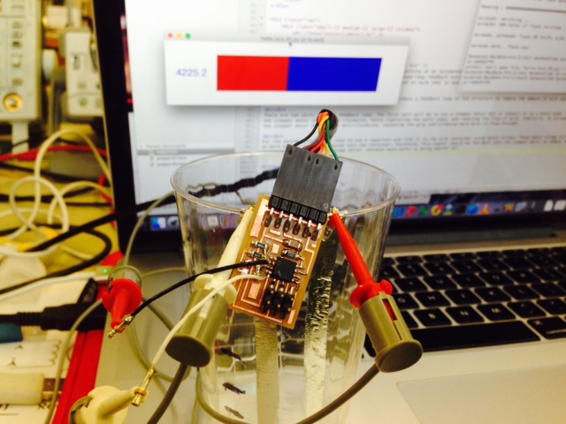
For the second part, I will need to use a capacitor and link it to the milk container using metal strips. These metal strips will conduct voltage better
as more milk or liquid is poured into the container. Therefore, this signal should be fed back into the stepper motor to reduce the flow of milk
as the capacitor conducts voltage better (because more water is being poured in).
Here is the video of the stepper motor rotating to tighten the grip!
Here is the video of the capacitor reacting as more liquid is poured in!
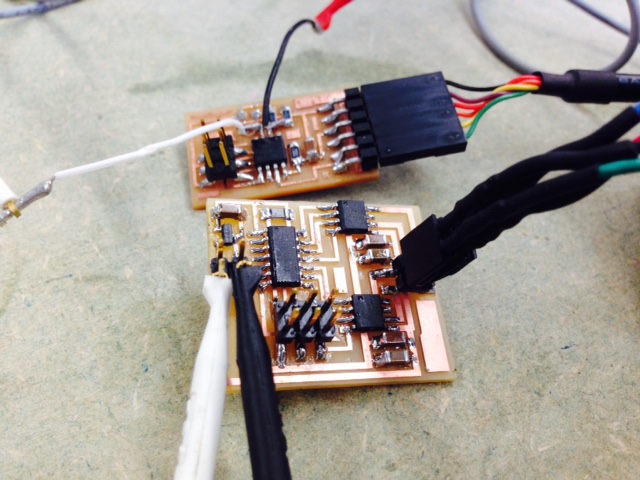
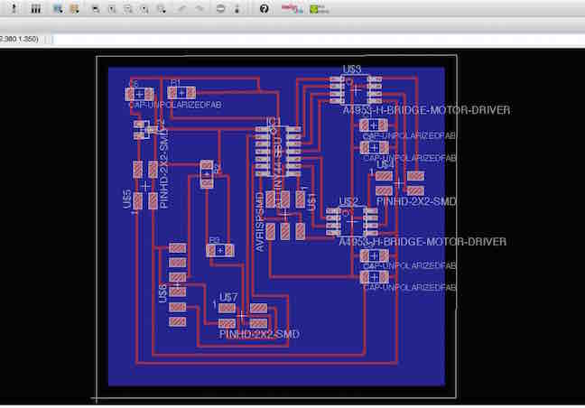
Next, I am going to try to get both the stepper motor and the capacitor board to talk to each other - therefore I wanted to design a new circuit in Eagle
that will combine both of the functionality of both boards.
Working to connect the stepper motor board and the capacitor board, I also needed a refresher of using Eagle, and hence am documenting the steps below:
(1) Open a new schematic and upload fab library. Next, type "add", and go to library to choose the parts one by one (look for "fab"). To connect them, use "Nets, Label, Name" to start connecting parts that are the same.
(2) I will need to connect 4 parts from capacitor onto the stepper motor board. 4 parts are "FTDI, Resistor 2, Resistor 3, and J3 power". In order to connect them, I need to look for empty pins on the Tiny44 on Motor board. Once I have done that, I also need to
connect the "GND" and "VCC" onto the stepper motor board.
(3) Convert schematic onto board: After that, I can start to orientate the parts onto the board that will best allow the circuits to flow correctly. Use "route, rats, ripup, or show" to connect, reduce lines, and check the Eagle system to ensure
that all is correctly connected.
(4) Convert into image ("png") Once completed, you can use "display" function to display only top or bottom. First, make the borders small to fit the board,
then display bottom layer, type in rect to create the outline for the board. Display none, then display top, and export to .png image (using 1,000 dpi for resolution).
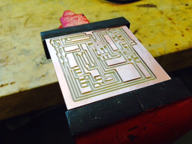
After using Eagle to design the board, I use the Roland machine to mill the board. It took some refresher again, but I was able to complete it!
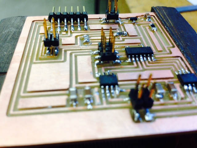
Next, I went on to add all the relevant parts for the PCB onto the board.
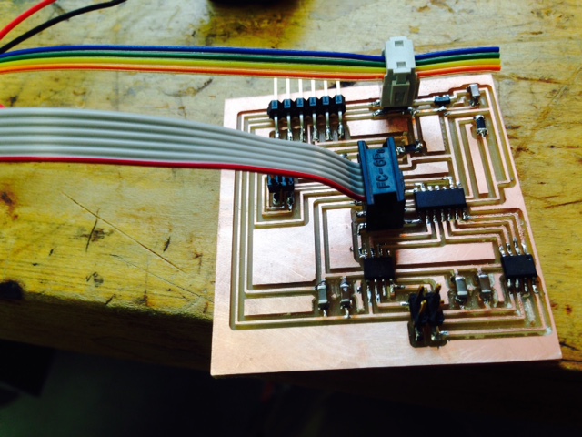
Sadly, after I completed all the soldering, designing, and mounting the relevant parts (which took me nearly 2 days to refresh and get back on track),
the PCB didn't work. With the help of Rob, I tried to find out the reason behind why the board didn't work, but wasn't able to do it.
I am planning to re-do the Eagle design next week, and try again to work on this!
Here is the video of the capacitor reacting as more liquid is poured in!
Next, I am going to try to get both the stepper motor and the capacitor board to talk to each other - therefore I wanted to design a new circuit in Eagle
that will combine both of the functionality of both boards.
Working to connect the stepper motor board and the capacitor board, I also needed a refresher of using Eagle, and hence am documenting the steps below:
(1) Open a new schematic and upload fab library. Next, type "add", and go to library to choose the parts one by one (look for "fab"). To connect them, use "Nets, Label, Name" to start connecting parts that are the same.
(2) I will need to connect 4 parts from capacitor onto the stepper motor board. 4 parts are "FTDI, Resistor 2, Resistor 3, and J3 power". In order to connect them, I need to look for empty pins on the Tiny44 on Motor board. Once I have done that, I also need to
connect the "GND" and "VCC" onto the stepper motor board.
(3) Convert schematic onto board: After that, I can start to orientate the parts onto the board that will best allow the circuits to flow correctly. Use "route, rats, ripup, or show" to connect, reduce lines, and check the Eagle system to ensure
that all is correctly connected.
(4) Convert into image ("png") Once completed, you can use "display" function to display only top or bottom. First, make the borders small to fit the board,
then display bottom layer, type in rect to create the outline for the board. Display none, then display top, and export to .png image (using 1,000 dpi for resolution).
After using Eagle to design the board, I use the Roland machine to mill the board. It took some refresher again, but I was able to complete it!
Next, I went on to add all the relevant parts for the PCB onto the board.
Sadly, after I completed all the soldering, designing, and mounting the relevant parts (which took me nearly 2 days to refresh and get back on track),
the PCB didn't work. With the help of Rob, I tried to find out the reason behind why the board didn't work, but wasn't able to do it.
I am planning to re-do the Eagle design next week, and try again to work on this!
Next, I am going to try to get both the stepper motor and the capacitor board to talk to each other - therefore I wanted to design a new circuit in Eagle that will combine both of the functionality of both boards.
Working to connect the stepper motor board and the capacitor board, I also needed a refresher of using Eagle, and hence am documenting the steps below:
(1) Open a new schematic and upload fab library. Next, type "add", and go to library to choose the parts one by one (look for "fab"). To connect them, use "Nets, Label, Name" to start connecting parts that are the same.
(2) I will need to connect 4 parts from capacitor onto the stepper motor board. 4 parts are "FTDI, Resistor 2, Resistor 3, and J3 power". In order to connect them, I need to look for empty pins on the Tiny44 on Motor board. Once I have done that, I also need to
connect the "GND" and "VCC" onto the stepper motor board.
(3) Convert schematic onto board: After that, I can start to orientate the parts onto the board that will best allow the circuits to flow correctly. Use "route, rats, ripup, or show" to connect, reduce lines, and check the Eagle system to ensure
that all is correctly connected.
(4) Convert into image ("png") Once completed, you can use "display" function to display only top or bottom. First, make the borders small to fit the board,
then display bottom layer, type in rect to create the outline for the board. Display none, then display top, and export to .png image (using 1,000 dpi for resolution).
After using Eagle to design the board, I use the Roland machine to mill the board. It took some refresher again, but I was able to complete it!
Next, I went on to add all the relevant parts for the PCB onto the board.