The milk scanner allows you to take a series of 2D photos with different levels of milk, and convert these photos into a 3D image, which you can choose to 3D print out if you like.
1. The process of creating the framework
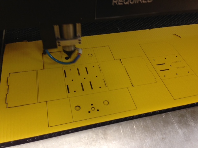
Using the guidance of James' and Nadya's Modular machines that Make, I worked to create
the modular framework using cardboard, which I used the laser cutter on. The 3D design files from their website can be found on their dropbox here.
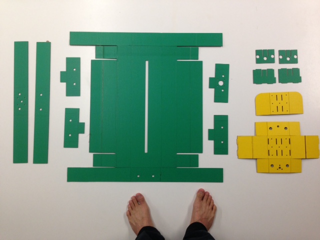
After laser cutting the necessary cardboard parts, I worked to re-construct the modular framework ("SCIENCE"), by using glue, weights, and putting everything
together into the appropriate structure.
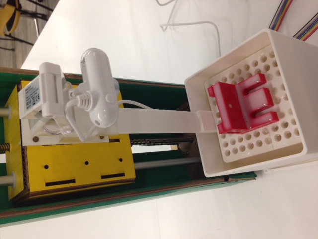
2. Creating the end effector using rhino + 3D printing
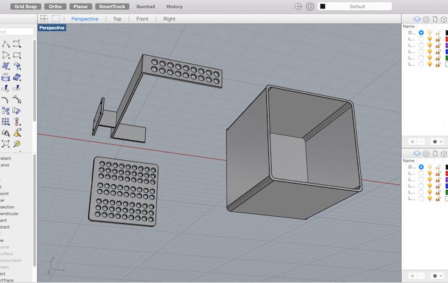
Next, I created a 3D design using the Rhino software for the end-effector. In creating the end-effector, I wanted a design that could act
as a platform to place the object, and move it vertically up and down through different levels of milk. I also needed a container
that was white (to enhance contrast), that was high enough to contain the right amounts of milk, and yet allow sufficient light to come through.
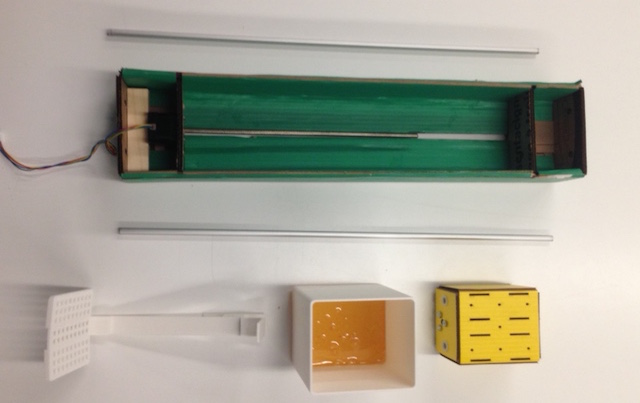
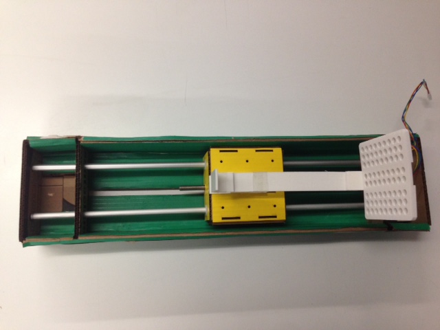
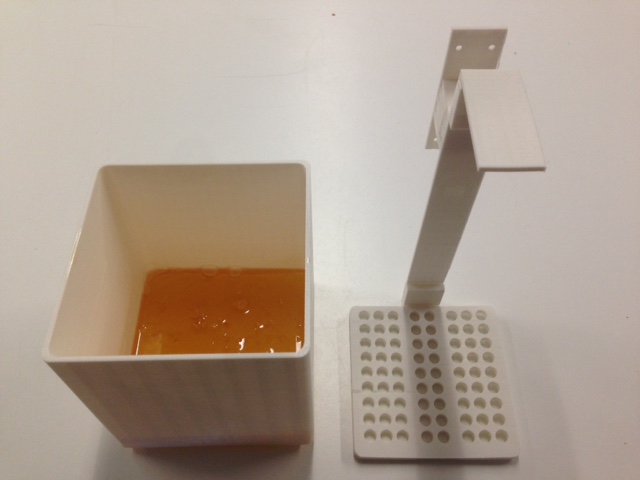
3. Assembling the end effector and the modular framework
After getting all the necessary parts ready, I assembled them all by attaching the end-effector to the modular framework using a combinations of
screws, tapes, and nuts. I also needed to factor in several things in my design including
1. How far does the camera need to be from the platform 2. How far should the end-effector move vertically up and down? 3. The platform
should be perforated so that there will be less resistance when it moves up and down.
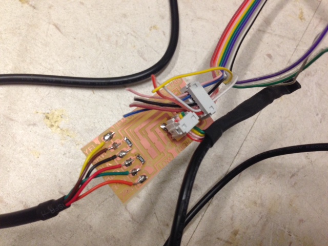
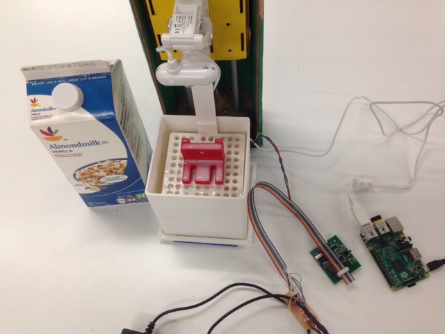
4. Setting up the electronics, gestalt node and software
I went forward to mill the Fabnet board, and connected the necessary wires to the right circuits. As the connection is unusual, I followed
closely the examples from Machines that make website, and connected the necessary routing.
To set-up the gestalt-node, I needed to do a series of programming and trouble-shooting on my macbook, including the below
1. Setup Python and Pyserial (will differ based on Mac, Windows, or Linux)
sudo python setup.py install
export PYTHONPATH=/Library/Python/2.7/site-packages
Look here to set-up your pyserial
2. Identify the appropriate USB port + mac troubleshooting
Find the appropriate USB port and replace it in your code (in my case python single_node.py) using "cd/dev", "ls | grep usb", and I found my
port to be "/dev/tty.usbserial".
For mac users I needed to save the below as a "path.py" file and execute this code "eval $(python path.py)"
######################################
# figure out mac path, save this as path.py and then run
# eval $(python path.py) in your terminal
import site, string
print "export PYTHONPATH=%s:$PYTHONPATH" % string.join(site.getsitepackages(), ':')
#######################################
3. Execute the python command + troubleshooting
python single_node.py
Sometimes you will need to run "rm test.vmp" after you set up
Also, you may need to press the "node" on gestalt node to help the system identify the X-axis.
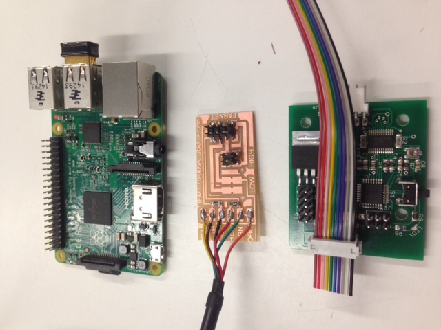
5. Image-capture using the Raspberry Pi
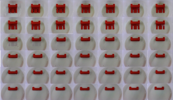
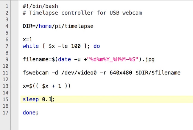
In order to capture the images, I wrote a simple code to capture 100 images with intervals of 0.1 seconds, hence capturing the images within 10 seconds.
From the picture above, you can see me assembling the 2D images into a series of timed photos with different levels of milk.
6. 3D image processing using ImageJ
Using the ImageJ software, I was able to collate all the necessary photos easily into a stack, find their edges,
and then process it using the Javacript software within ImageJ to create the 3D model. There is a built-in plugin which you can download
for ImageJ, and that is the main software that will use in order to create the 3D image.
Step 1: Stack all the images together and find outline
ImageJ uses a simple stacking function to collate all the images into one, and use a Sobel edge detector to highlight sharp changes in intensity in the active image or
selection. Two 3×3 convolution kernels are used to generate vertical and
horizontal derivatives. The final image is produced by combining the two derivatives using the
square root of the sum of the squares.
Java3D is an extension to Java, providing a library for hardware-accelerated 3D rendering.
It runs on any common platform, but there are different binaries for Windows, Linux and Mac OS.
Download Java3D here and use it here
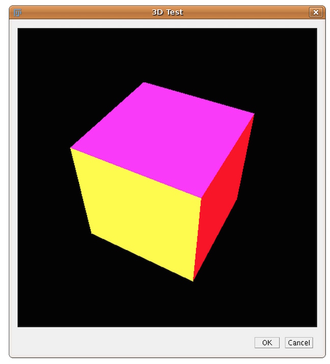
Step 2: Using Java3D to create 3D image
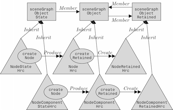
Java 3D is a scene graph based 3D application programming interface (API) for the Java platform. It runs atop either OpenGL or Direct3D. Since version 1.2, Java 3D has been developed under the Java Community Process. A Java 3D scene graph is a directed acyclic graph (DAG).
Compared to other solutions, Java 3D is not only a wrapper around these graphics APIs, but an interface that encapsulates the graphics programming using a true object-oriented approach. Here a scene is constructed using a scene graph that is a representation of the objects that have to be shown. This scene graph is structured as a tree containing several elements that are necessary to display the objects.
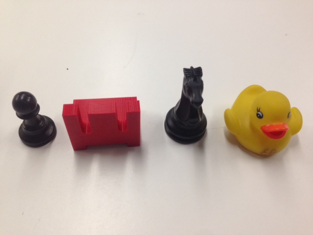
The milk scanner - what will you 3D scan?