This week was devoted to getting machines ready to present.
Tube Cutter
Prior work:
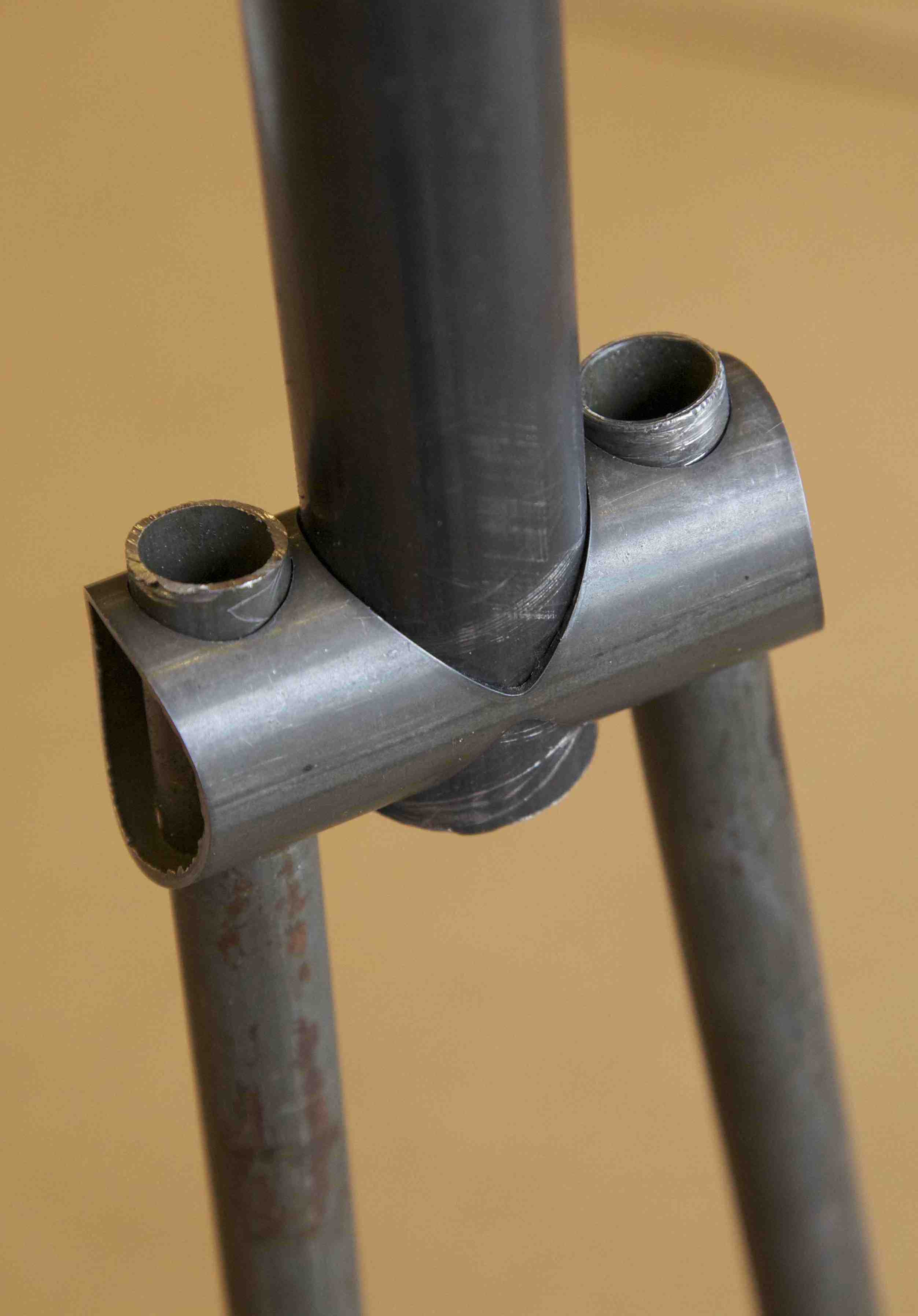
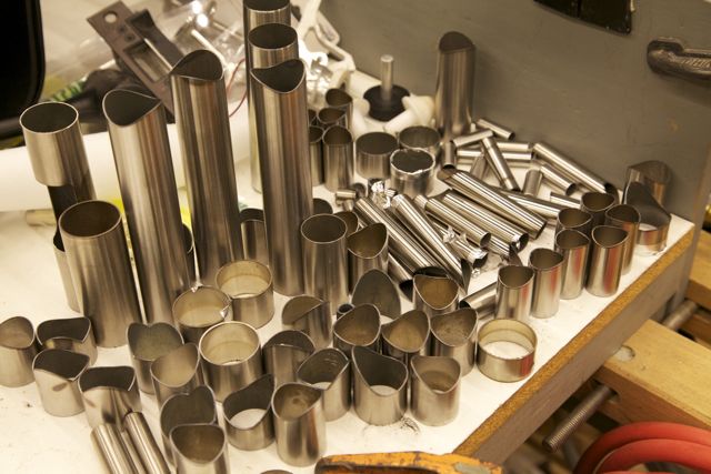
Building off the idea of having a small precise working volume that we can shift over a large piece of stock. Why pay for precision over a large distance if we only use it locally?
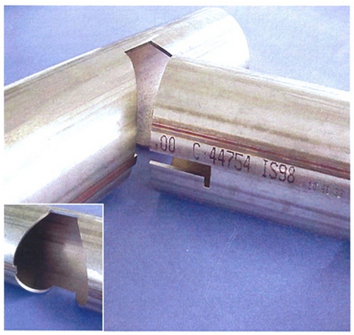
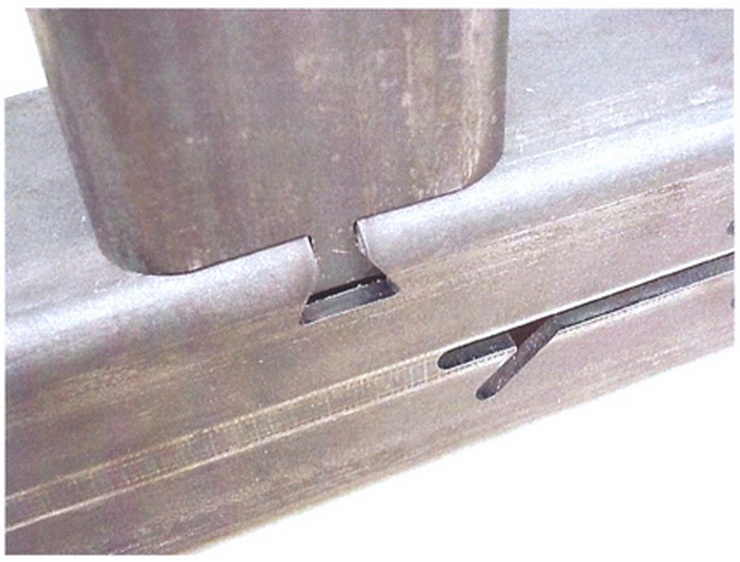
Inspiration from LT Technologies:
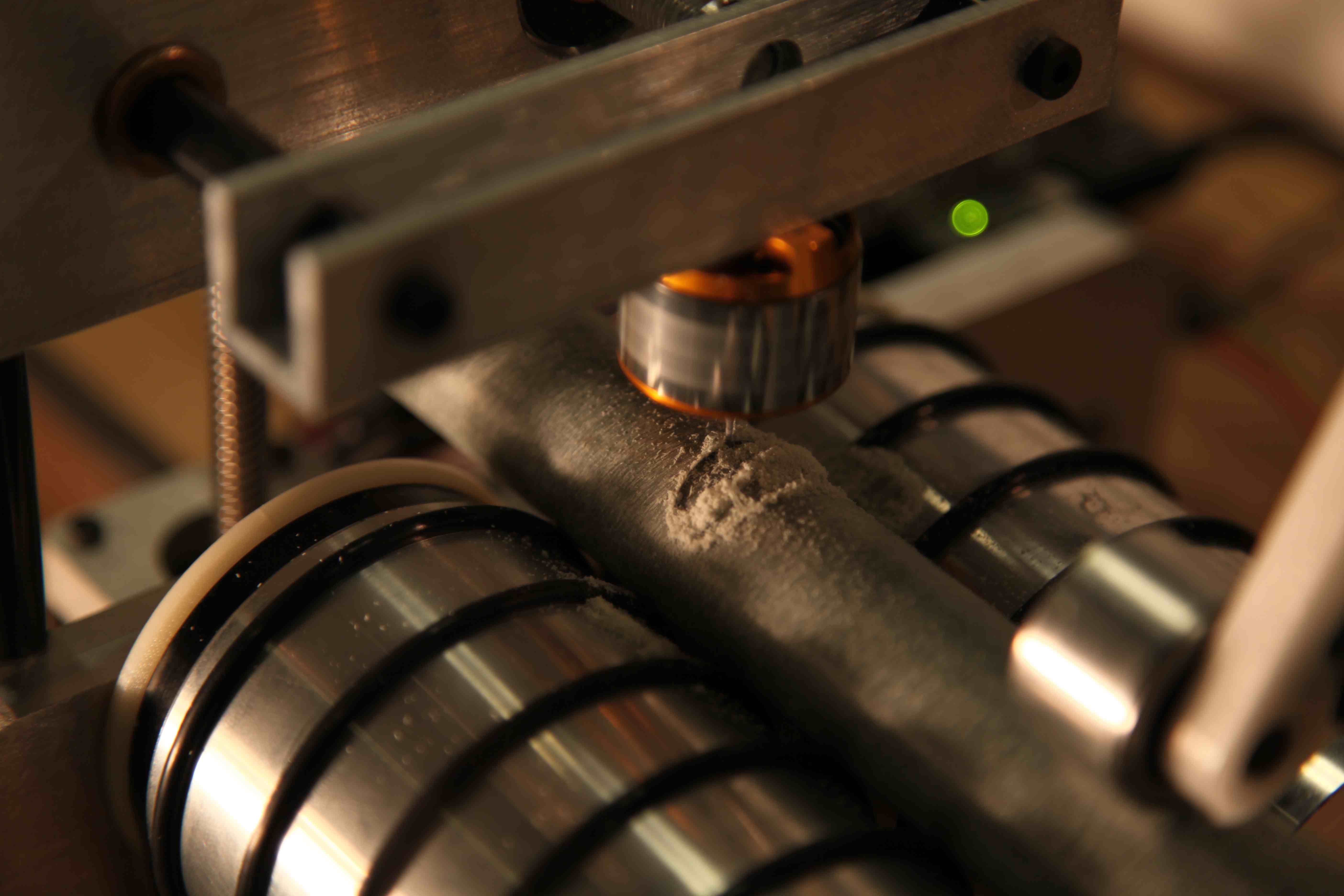
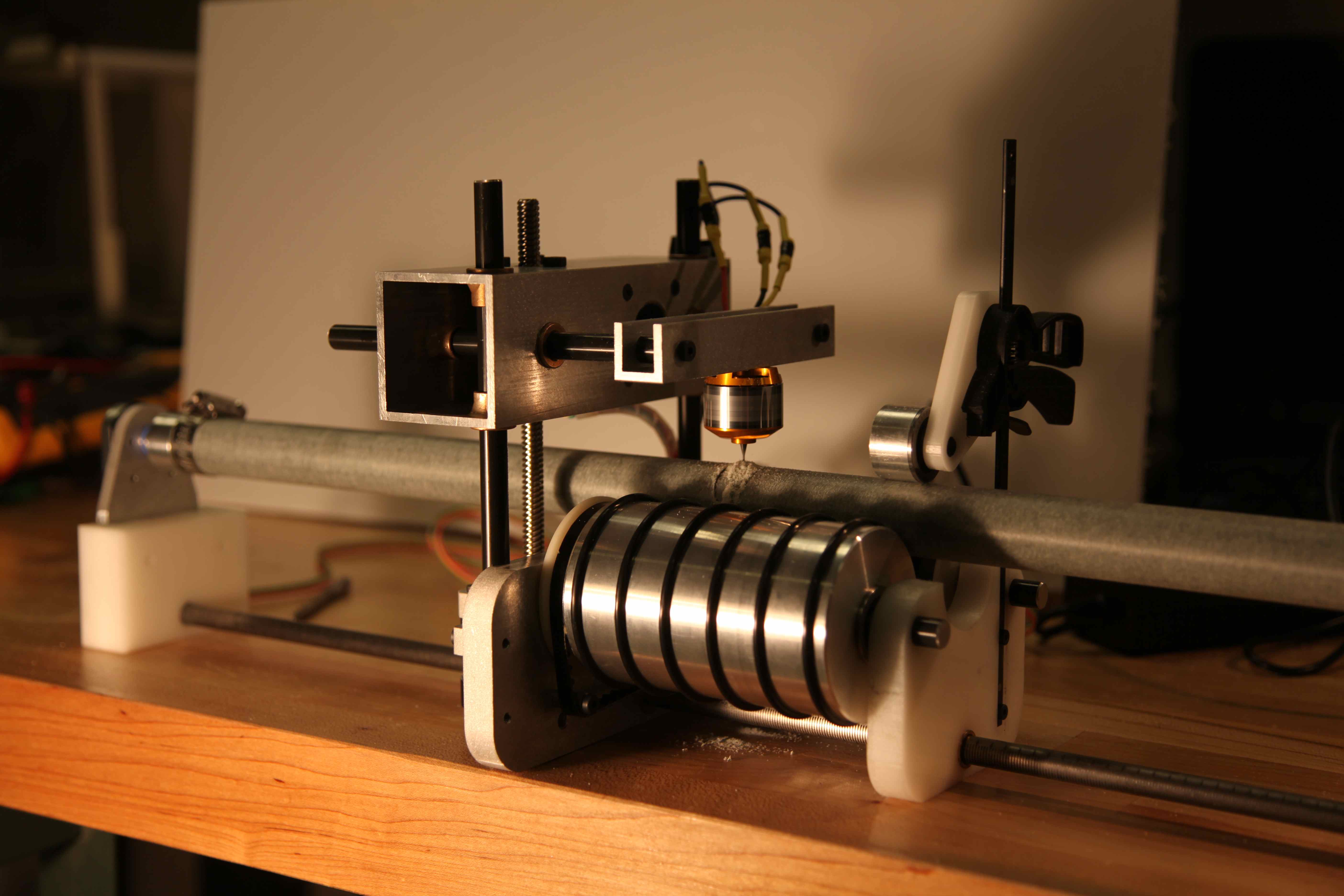
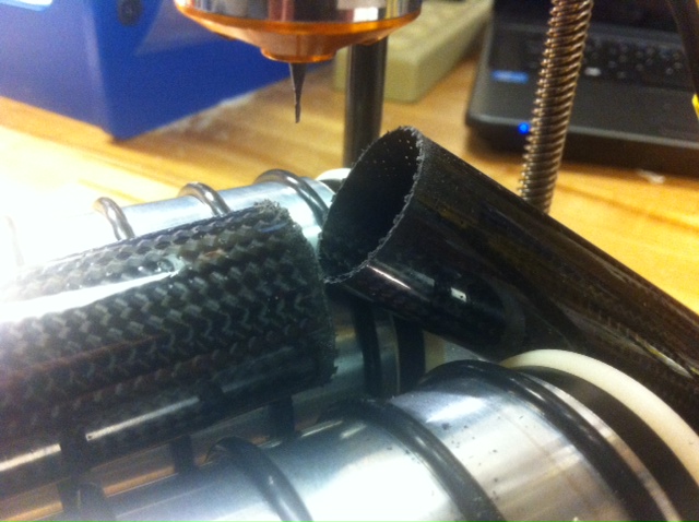
This week I tried to make the critical improvements to my tube mill that would make it usable. I was happy with how the final kinematics came together. I turned nice aluminum rollers to replace the slightly wonky 3d printed version. shiny. I added a sliding axis to control distance along a long tube feedstock. To fit this, I had to re-route my belt drive for the x axis.
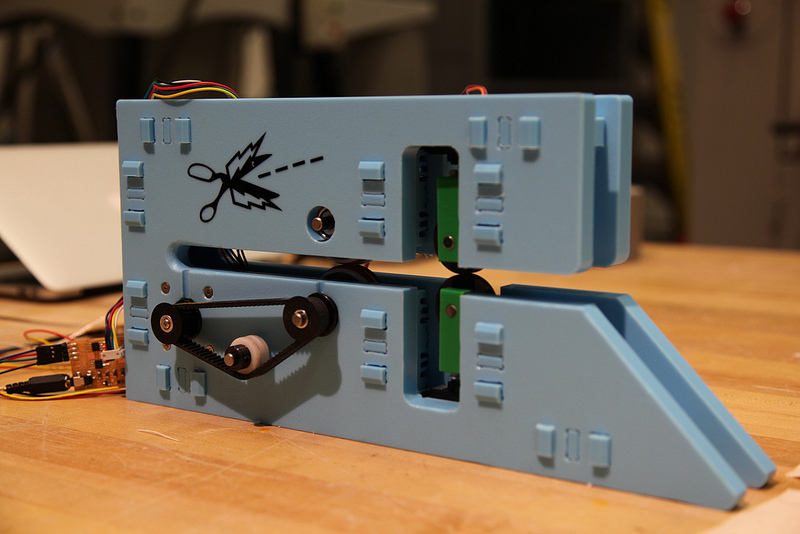
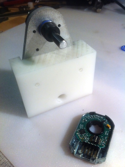
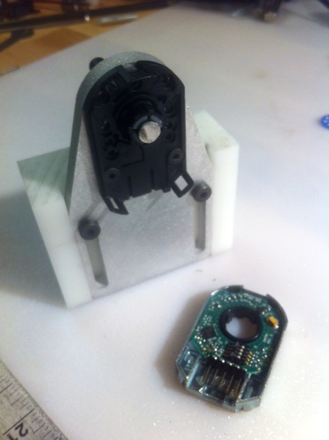
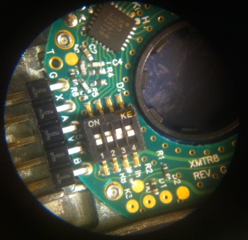
I added a sliding tube clamp with an encoder. This allows us to work on more than one point along the tube without losing our relative position. Thanks to Will for the great encoder package. It's an incremental capacitive encoder from CUI with adjustable resolution (see DIP switches below) that can clamp to a wide variety of shaft diameters. I used a 1/4" shaft mounting to an aluminum plate with a bearing and thrust bearing. The back side of this shaft is clamped into the encoder, while the front side carries a mount for tube stock. The whole plate is adjustable vertically to accomodate how different tube diameters will sit in the rollers.
The second functionality of this encoder is to account for the backlash in my belt drive for the x axis, and detect any slip between the tube stock and the x axis rollers.
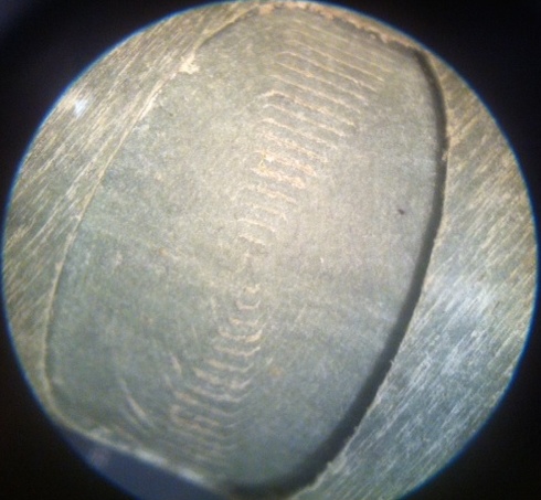
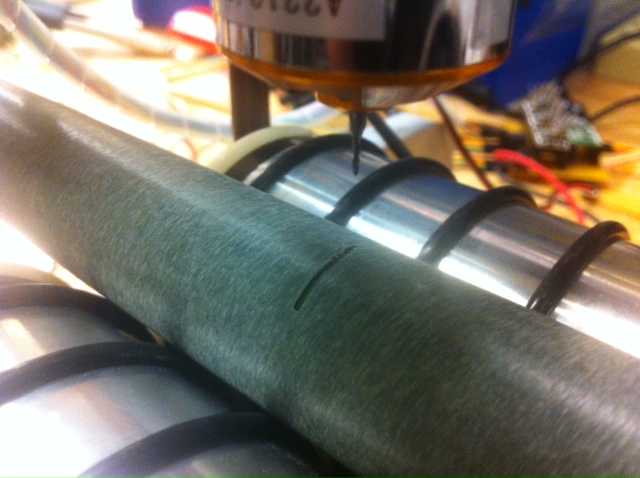
This base is mounted on a 3/8" rod that tracks through the main machine. To keep track of how far along the tube we are positioned, I decided to go old school and just etch a ruler into the rod. For the precision we expect/care about, this is good enough. Following these posts (A and B), I used dry moly lube as a marking agent to laser etch the marks and labels for the ruler. To make sure I was aligned over the 1 meter length, I first cut a series of holes into an acrylic substrate. I installed 6-32 machine screws into these holes and used the pan heads to constrain the rod in line with the laser cutter X axis.
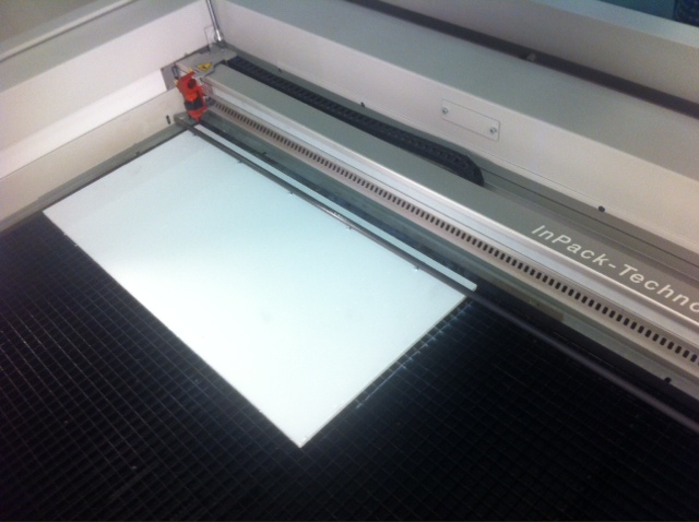
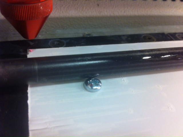
This worked great, with the one caveat that the tube heated up during etching and warped a bit. This resulted in being slightly out of focus at one end of the ruler, but it still reads fine. In the future, I'd use stainless or aluminum for this ruler, but all I had in the right size at the right time was mild steel.
I spent a lot of time this week implementing a control system for this machine. For better or worse, I tried to write the whole thing from scratch. This was an experiment with trying to strip as much logic from the microcontroller as possible and handle most of the motion control from javascript.
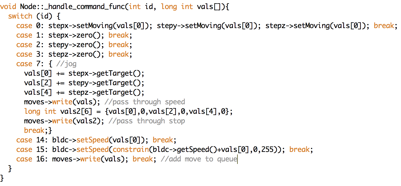
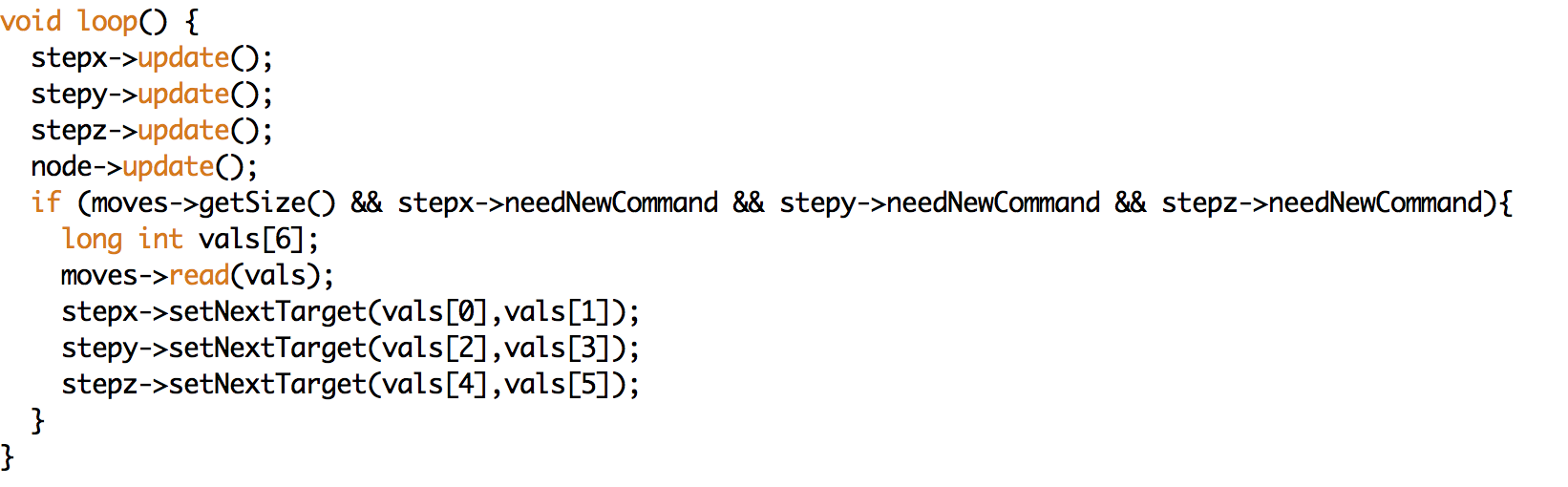
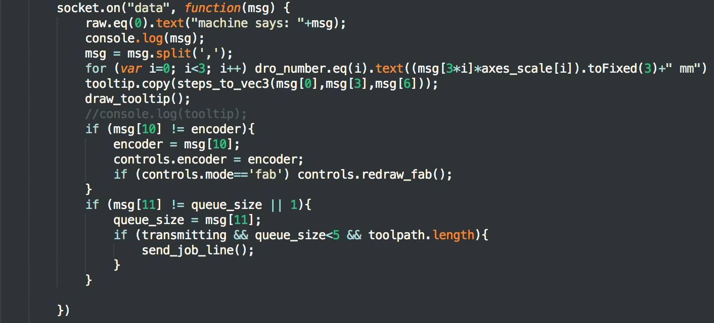
In contrast to last week, the micrcontrollers are now running an event-driven, queue-based control loop. The main loop manages a FIFO buffer of 6-tuples containing targets and speeds for each stepper motor. Each stepper object sets a flag when it is ready for a new tuple. When all the steppers are ready and there is another tuple in the queue, it gets dispatched and the stepper object executes it (including ramping in and out). Getting this working correctly was a much bigger challenge than I anticipated this weekend (Is it working correctly?).
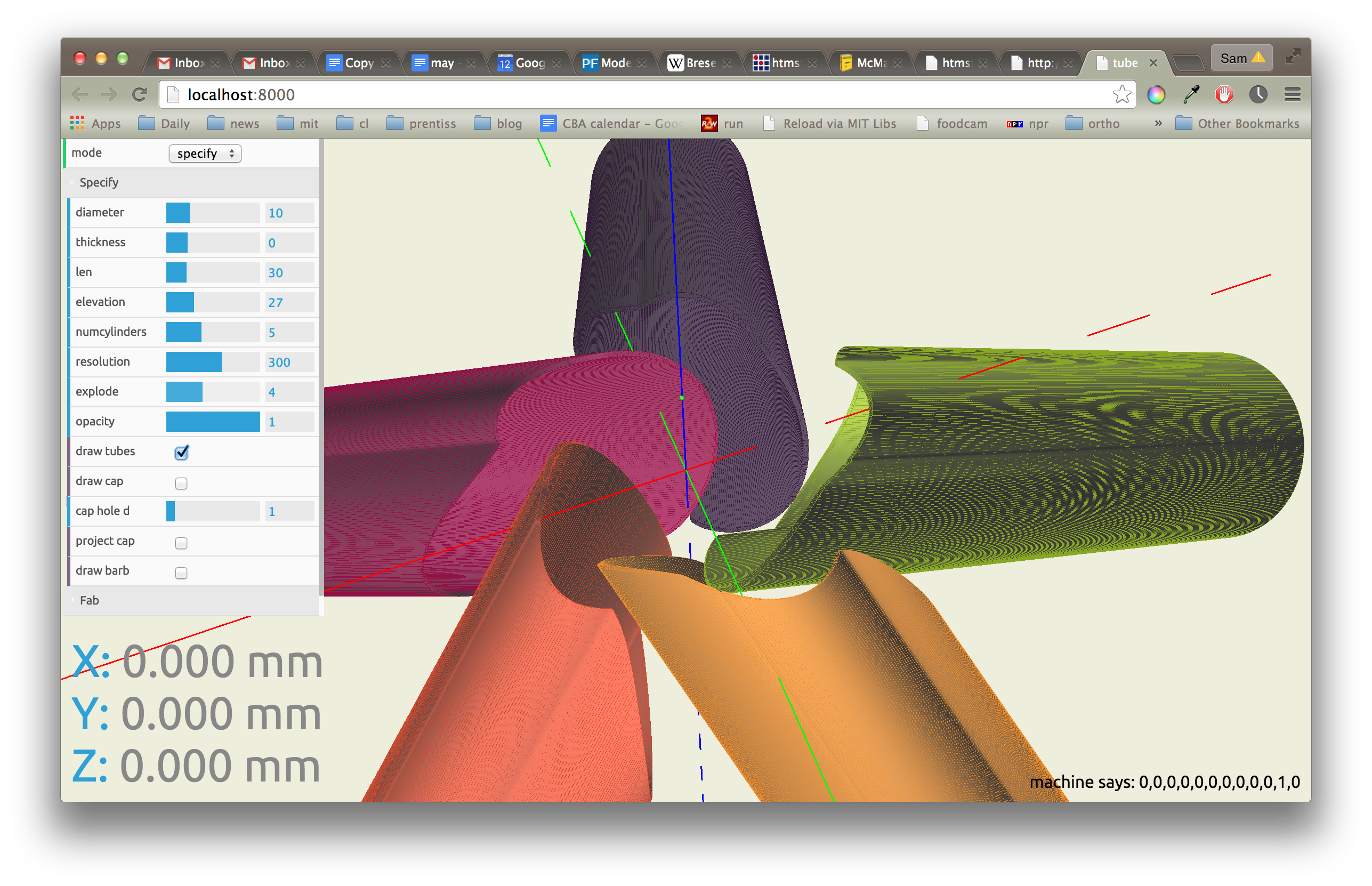

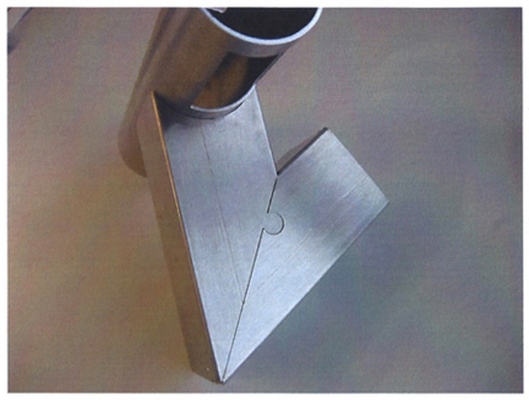
After debugging some motor driver issues this morning, I ran my first test on a "hard fiber" tube from mcmaster (aka compressed paper). The path following looks great! Some issues with unit conversion.