Eduardo is a (semi) accurate plotting robot. unconfined in space, Eduardo can roam around the world and plot on the ground.
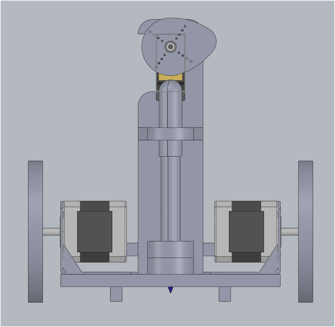
Cad
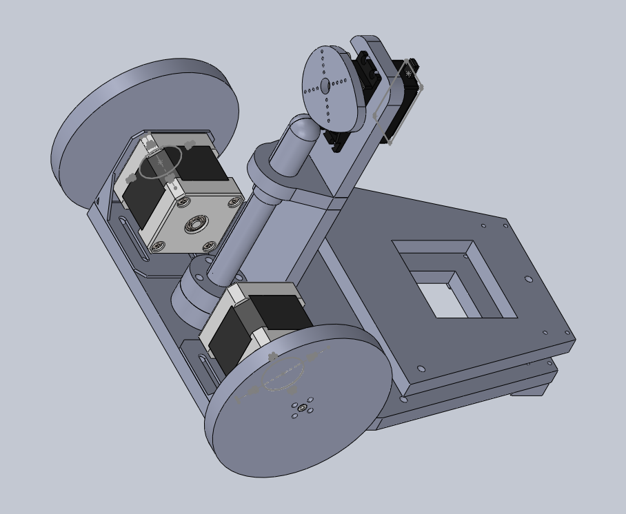
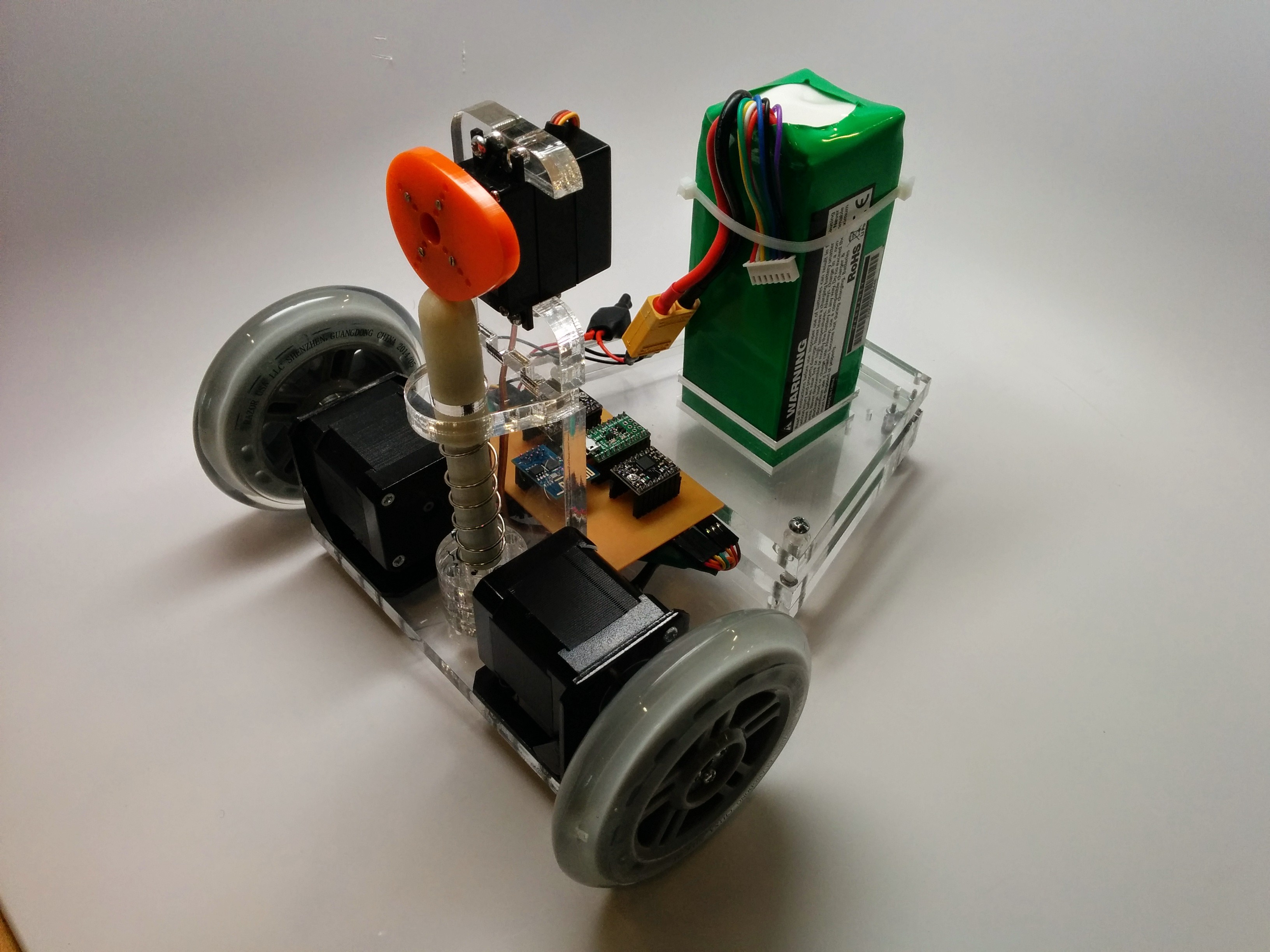
Eduardo needs to have high friction wheels and a lot of weight to avoid slippage. This design can be improved. most importantly, the center of mass needs to be close to the wheels, rather than in the back.
Laser cutting acrylic for the body and 3d printing the marker holder.
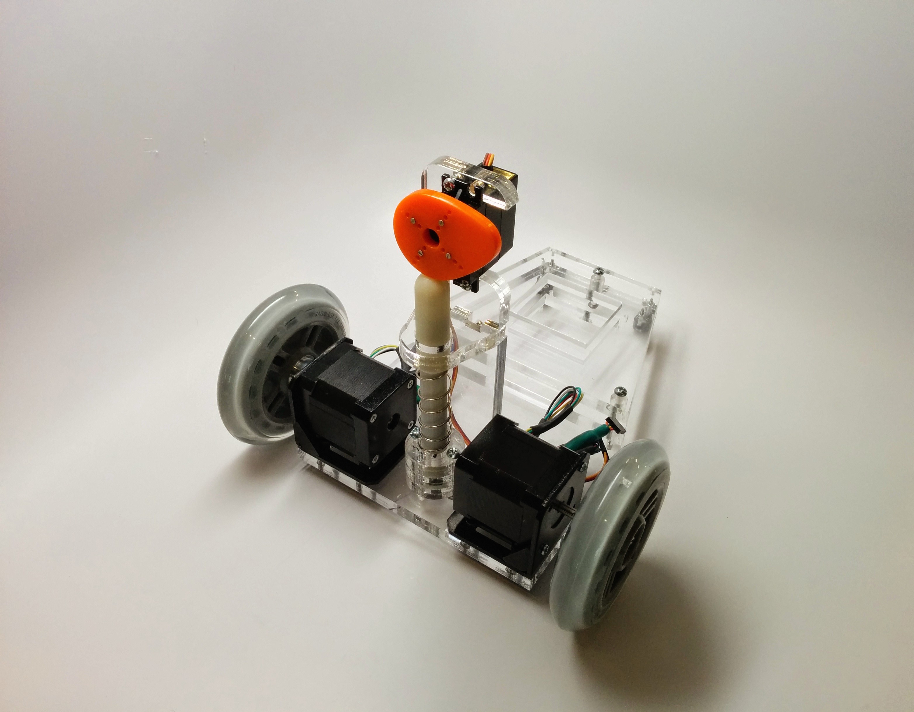
I used razor scooter wheels for the front and ball casters for the back.
Electronics
Components:
- Steppper motors
- Servo
- 22.2V LIPO battery
- BEC Step down regulator
- Pololu A-Star 32U4 Micro
- Polulu A4988 Stepper Motor Driver Carriers, Black Edition
- ESP8266 WIFI Module
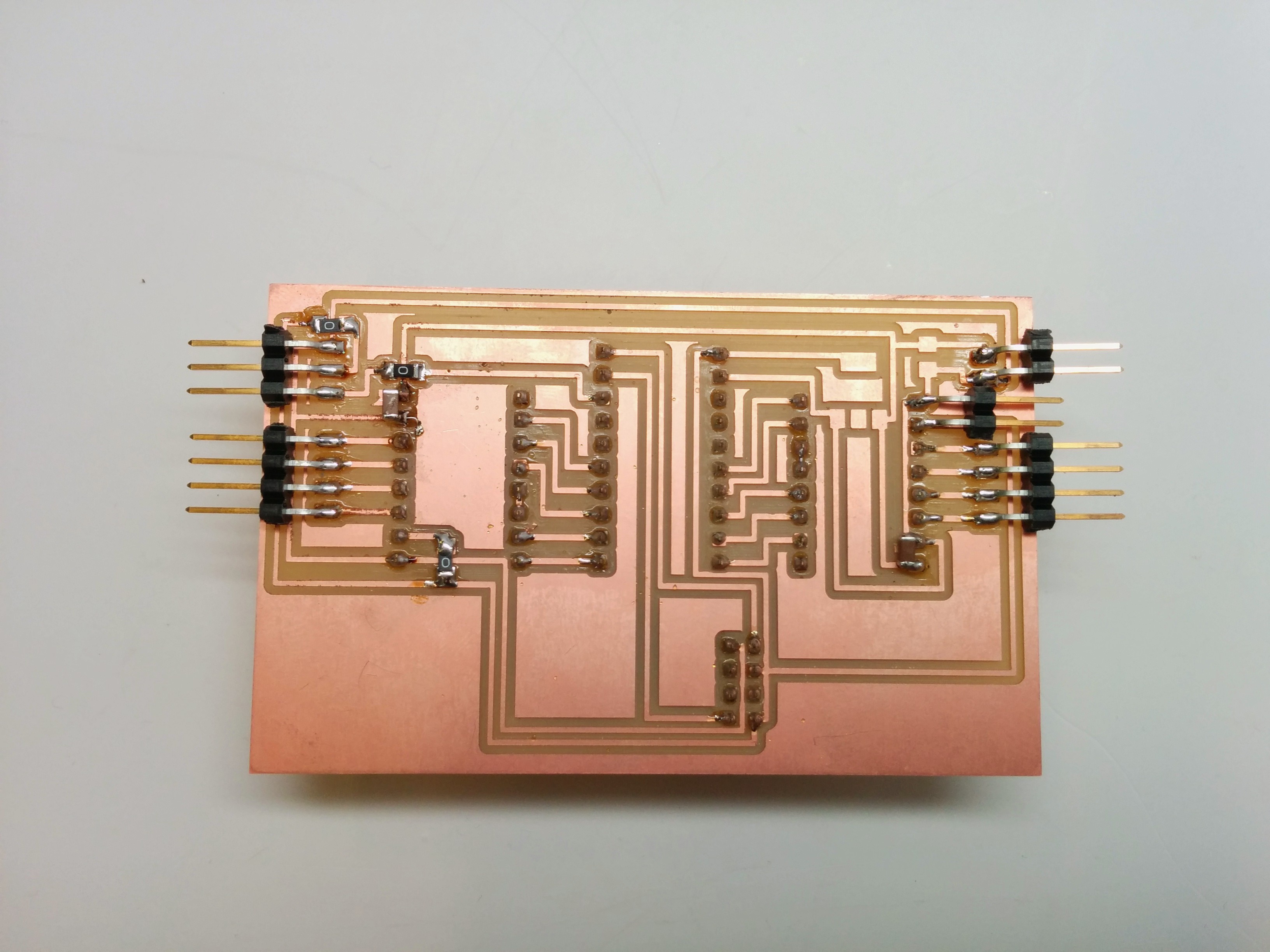
Custom circuitry to connect everything together
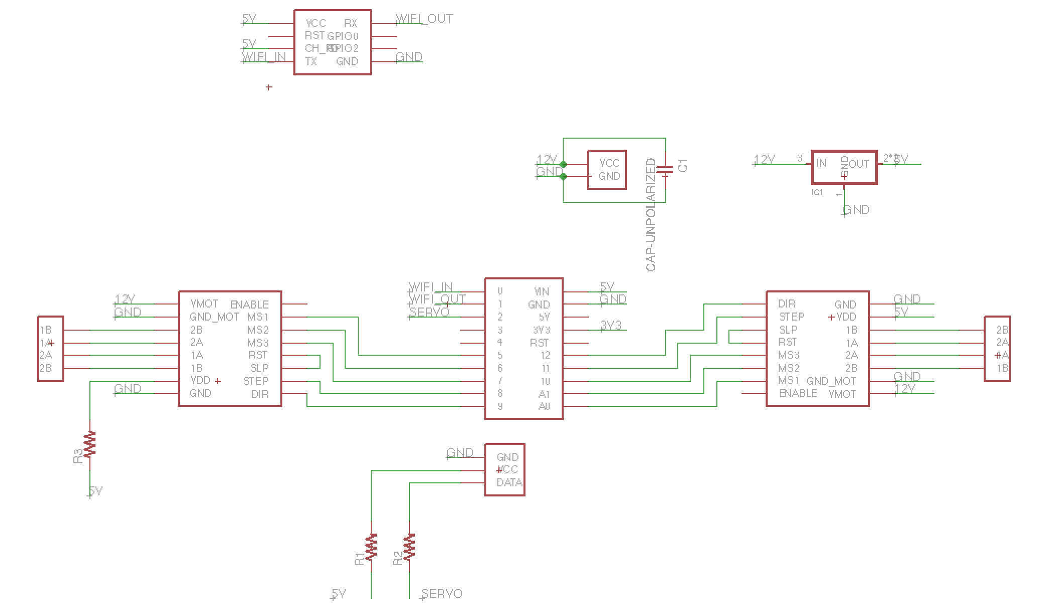
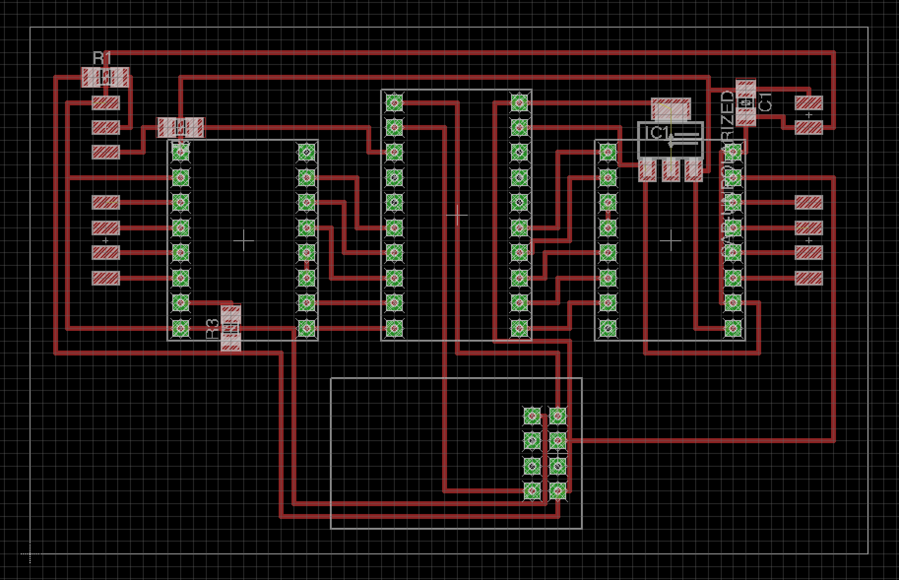
 The circuit was hacked so that 5V are received externally rather than the SMD regulator and individual capacitors were placed on each of the step motor drivers.
 Oops. the usb jack is on the wrong side.
In the process I fried 7 step motor drivers. The grave yard:
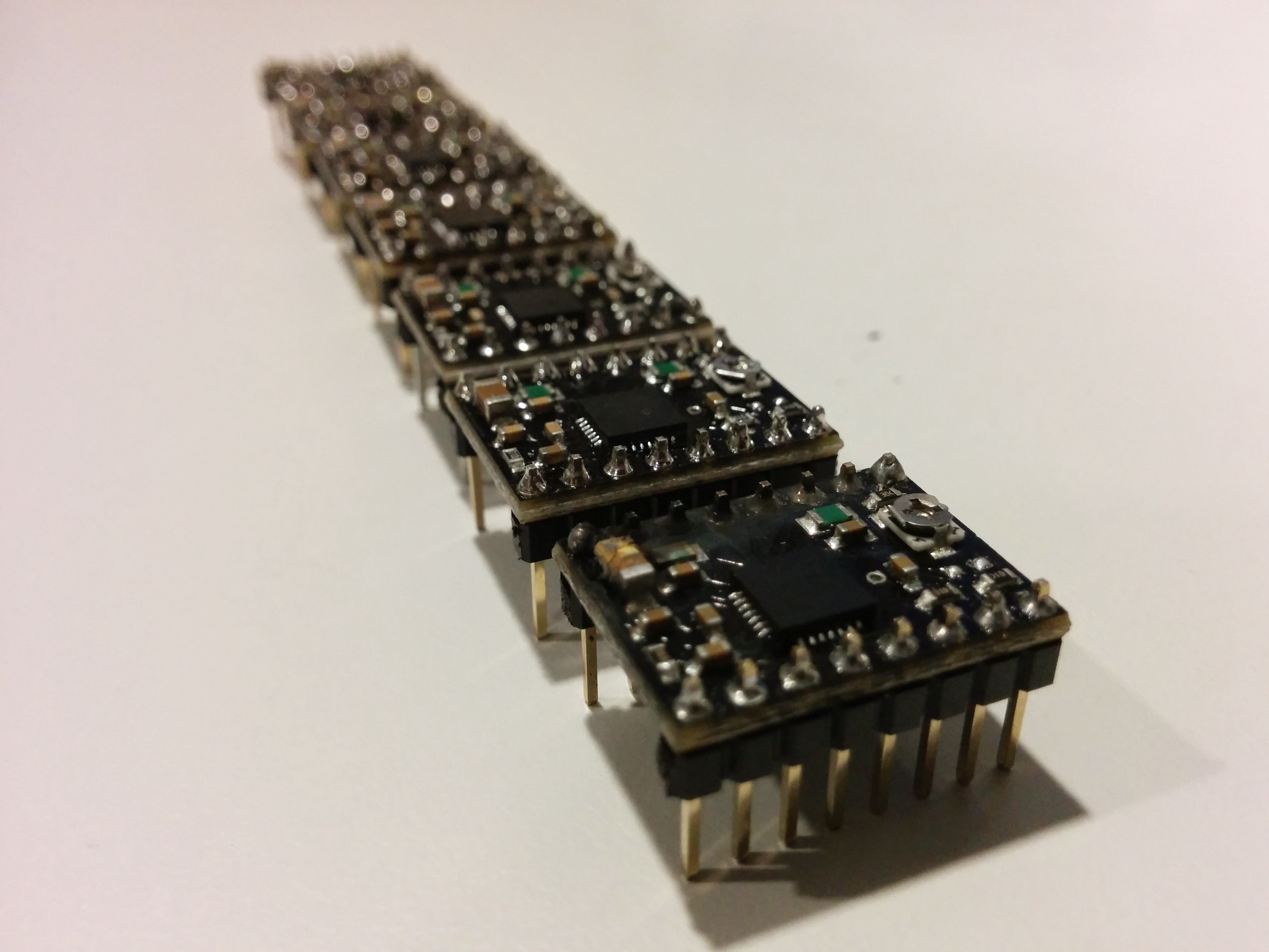 (TODO: list all the ways you can burn a step motor driver)
Putting it all together
Embedded Software
Eduardo handles command packets comprised of 5 integers: MARKER_DOWN, LEFT_DIRECTION, RIGHT_DIRECTION, STEPS. these were meant to be fed via WiFi but the ESP8266 was not functioning well so for now these are fed initially via Serial.
#include <Servo.h>
#include "ESP8266.h"

int servoPin = 2;
int rightStepPin = 8;
int rightDirPin = 9;
int leftStepPin = 11;
int leftDirPin = 12;
int yellowLedPin = 13;

int ANGLE_UP = 110;
int ANGLE_DOWN = 45;

Servo servo;


void setup()
{
  servo.attach(servoPin);
  servo.write(ANGLE_UP);
  pinMode(rightStepPin, OUTPUT);
  pinMode(rightDirPin, OUTPUT);
  pinMode(leftStepPin, OUTPUT);
  pinMode(leftDirPin, OUTPUT);
  pinMode(yellowLedPin, OUTPUT);
  Serial.begin(9600);
}

void stepTogether(int duration)
{
    digitalWrite(rightStepPin, HIGH);
    digitalWrite(leftStepPin, HIGH);
    delay(duration);
    digitalWrite(rightStepPin, LOW);
    digitalWrite(leftStepPin, LOW);
    delay(duration);
}

void move(int down, int leftDir, int rightDir, int steps, int pulse) {
  Serial.print("Pen Down: ");
  Serial.print(down);
  Serial.print(", Left Direction: ");
  Serial.print(leftDir);
  Serial.print(", Right Direction: ");
  Serial.print(rightDir);
  Serial.print(", Steps: ");
  Serial.print(steps);
  Serial.println();

  int angle = down ? ANGLE_DOWN : ANGLE_UP;
  if (servo.read()!=angle) {
    Serial.print("writing servo angle : ");
    Serial.println(angle);
    servo.write(angle);
    delay(500);
  }
  digitalWrite(leftDirPin, leftDir);
  digitalWrite(rightDirPin, rightDir);
  for (int i=0; i<steps; i++){
    stepTogether(pulse);
  }
}

void loop() {
  int i = 0;
  int commands [512];
  if (Serial.available() > 0) {
    while (Serial.available()){
      commands[i] = Serial.parseInt();
      i++;
      Serial.println(commands[i]);
    }
    digitalWrite(yellowLedPin, HIGH);
    delay(10000);
    Serial.print("Got commands: ");
    Serial.println(i);
    for (int j=0; j<(i/4-1); j++) {
      int b = j*4;
      move(commands[b], commands[b+1], commands[b+2], commands[b+3], 10);
    }
    digitalWrite(yellowLedPin, LOW);
  }
  delay(100);
}
Path planning
Eduardo has a python script that accepts an svg file and a serial port. It parses the svg, create commands for eduardo and sends them via the serial port. It currently only translates
$ python eduardo.py new_svg.svg /dev/tty.usbmodem1411 9600
Start
127.6 648.0 864.0 1156.0
864.0 1156.0 864.0 95.6
864.0 95.6 1598.4 648.0
[[0, 127.6, 648.0], [1, 864.0, 1156.0], [1, 864.0, 95.6], [1, 1598.4, 648.0]]
marker:  0 , turn: 11.1397946575 , distance: 660.443608494
marker:  1 , turn: 44.2606446019 , distance: 894.622244302
marker:  1 , turn: 124.599560741 , distance: 1060.4
marker:  1 , turn: -126.949703677 , distance: 918.960891442
[0, 0, 1, 24, 0, 1, 1, 660, 1, 0, 1, 98, 1, 1, 1, 894, 1, 0, 1, 276, 1, 1, 1, 1060, 1, 1, 0, 282, 1, 1, 1, 918]
Results
Hardcoded octagon:
More to come...