Male and female parts for punch pressing the tiles
Note:
In this design, there is a 2 mil offset between parts A and B.
This was designed to be used with 1/16 balls.
(Offset was later reduced to 1 mil).
May 4, 2009
Part Size
final ball diameter = 1/16"
part width = 6/16" = "1/3-inch part" (0.375")
thinner: 0.02" = 1/3 of the ball diameter
thicker: 0.04" = 2/3 of the ball diameter
Goodbye GIK, hello snap tiles: two-layer parts with epoxy and balls (Part PDF spec)
 - Conductive tiles and insulating tiles
 - Triangle vs. cross: zig-zag, no shear lines?
 - Balls vs. pegs: chamfered edge
 - Cut them in sheets, connected by tabs
 - Alignment rods for multiple layers
 - Flow spheres over the layers
 - Final dimensions: 50 mils?
 - Tool for cutting shim stocks: alternating teeth?
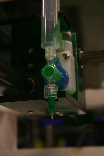
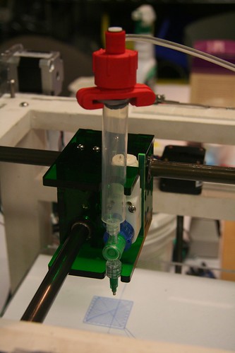
2. Pick and place
Vacuum pen: Press the button with linear gear (Mount PDF spec)
Motion sequence:
 1. Button press
 2. Move pen down
 3. Button release
 4. Move pen up
 [move x-y]
 5. Move pen down
 6. Button press (extra force down here would be useful...)
 7. Move pen up
 8. Button release
Press-fit force at step #6
How to hold the piece down as it's released...?
To do:
1. laser cut and assemble conductive and non-conductive parts
a. can we cut a single material by etching smaller different depth holes?
b. can we bake the parts together so they will stick?
c. what kind of glue would work and at what scale
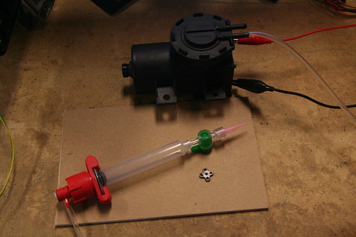
2. figure out suction cup mechanism
a. valve
b. suction cup itself
c. how will the suction cup press the part into place
d. pump
April 13, 2009
1. Cam prototype
2. Parts design
Options: GIK, miniature Legos, or custom part
- Custom part design
[Need picture/video here]
- George Popescu's GIK page, paper draft
- 1/10mm size, SOIC scale
- Metals and functional materials >> Neil strongly suggests 2D parts (use new lasercutter)
- Start with a bed of lattice
- No meterology(sp?) on the printer
- We can start with 2 grooves (4 is more than we need)
- 90-degree rotation: 2 heads vs. 1 rotating head
- Spacers
- Circuitboard fab: killer app, counter 3D printers
- George's GIK assembler has 4 blades - 1. Building 2. Detecting errors 3. Removing errors 4. Rebuilding removed parts
- GIKs cut in two sizes: 0.272" for 5/64" thick acrylic (perhaps supposed to be 1/16") and the other 0.365" (7/64", approx 1/8" thick)
- Empty space - solder leak?
For robust design with that reduces the number of motions necessary per
part assembled, we use three principles:
Periodic Juxtaposition: Use a sewing machine-like head in combination with
a platform moving at constant speed (as opposed to a jerky-arm model)
Part Aperture: For small numbers of parts, we propose columns of feed stock parts
with individual apertures that release parts in coded order. For large numbers of parts, we propose a cylindrical array of
part columns with a fixed aperture that releases parts in a coded order
Funnel Queueing: Once release from their apertures, parts slide into funnel that queues the parts for
placement by the pecking element. Introducing a funnel eliminates the need for a 2-d coded motion that selects
the desired part from an array of feed stock.
- what will (and won't) it be able to do?
In this case, "2-d" refers to the motion of a platform which supports the part. We assume that snap, adhesive,
or other bonding can be initiated mechanically by the pecking element.
- what are the benefits (and disadvantages) over current practice?
By separating oscillation from translational motion, we achieve a robust design.
Make multi-layer pieces: Operand layers (glues, resin, magnet, copper etc.) and coded dimples optional
Assemble the pieces: Achieve multiple configurations using robotic arms and syringed functional materials
Part 1. Make multi-layer pieces:
Combination of printer/copier + iron + bandsaw
Part 2. Assemble the pieces:
Achieve configurations A-F.
Robotic arms pressfitting + injection syringe
Can do:
Feed
Cut
Layer
Glue
Coded dimple
Grab (2-spot or 4-spot)
X-Y-Z movement and rotation (assuming an innovative gantry)
Press fit
Melt and frost-dispense materials
Sort and store
Can't do:
tba
Which parts exist, and which will require development?
We can repurpose many coper/printer functions like sorter trays.
Syringe injection of melted materials (solder etc) exists.
Robotic arms exist, but we need to investigate their capabilities and alternatives.
how much will it cost?
tba
How fast will it be?
Assembly alone could be one piece per second. It is the first part of making multilayer materials (like copier) that could be slow. If this part is replaced by active extrusion it may become faster.