Table of Contents
Communication
of Factor Graph to Rendering Component
Communication
of Oct-Tree to CAM
Description
Language for VM Rules and Capabilities
Architecture Diagram
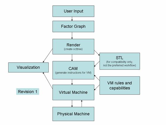
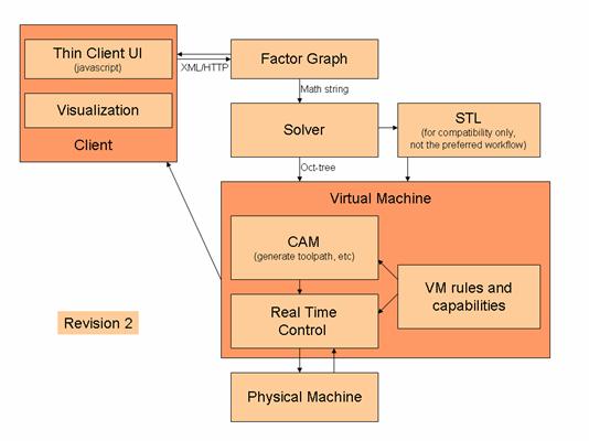
Description of Components
User Input
Users may provide input in a variety of ways, all supported by the primary user interface. Possibilities include, but are not limited to:
- Directly constructing/editing the factor graph
- Directly writing satisfiability constraints
- Importing images
- Importing other CAD formats
Factor Graph
The factor graph describes physical and conceptual components and their relationships. For example, nodes in a factor graph might be “sphere”, “radius” and “cylinder”. The “sphere” and “cylinder” might have properties defining their location. The “radius” node might feed into both the “sphere” and the “cylinder” nodes, in order to constrain both of them to have the same radius.
Render
The rendering component consists of software capable of performing the following distinct tasks:
- Convert the factor graph into a representation described by interval arithmetic on an oct-tree.
- Create a facetized representation of the geometry (triangles) for visualization or STL output (STL being much lower priority). Note that the triangulation for visualization and the triangulation used for file export may be different, because there could be significantly different resolution requirements.
CAM
The
STL
The ability to read and write STL files should be considered somewhat lower priority, since it is not part of the recommended workflow. However, it is almost certain that we will encounter situations in which it will prove useful for interfacing with other tools.
Visualization
We should have 3D visualization capabilities. At a minimum, this is used for displaying the geometry that the user has defined. Ideally, we should also be able to show the state of the virtual/physical machines and the generated toolpaths.
Virtual Machine
The primary task of the virtual machine is to receive the
instructions from the
Notice that in this description, the Virtual Machine is not an optional part of the workflow. It is used for driving the physical machine, in contrast to other possible system designs where the VM takes the same instructions as the physical machine for input, and plays the role of a simulator, outside the main workflow.
VM Rules and Capabilities
The rules and capabilities of the machine consist of both data and logic. For a 3-axis extrusion machine, we might have rules like the following:
- 5 primary controls (“dimensions”?): x, y, z, extrusion temperature, extrusion speed
- Constraints on minimum and maximum speed in the xi+yj direction
- Minimum and maximum values for each dimension
- Maximum path length
- Quantity of extrudable material to be ejected before pausing
- Step size in the z direction
Physical Machine
The physical machine executes instructions supplied by the virtual machine, and where possible, supplies feedback to the virtual machine.
Design Goals
- This
system will be used for driving many different physical machines. For each
new physical machine, we must provide a new virtual machine, along with a rule
set describing its capabilities. Therefore, we want it to be as easy as
possible to add these new machines. This suggests that, wherever machine
logic can be generalized and moved into the
- We should keep the instruction set human-readable for as much of the workflow as possible. This has obvious implications for data formats, but also suggests some guiding principles for when certain logic should take place. For example, it is easier for a human to understand what is supposed to happen when you “move from x0,y0 to x1,y1 at speed v” than to interpret “move x axis at speed vx from time t0 to t1, while moving y axis at speed vy from time t0 to t1”. The former can be relatively easily visualized, and the user has some hope of figuring out which part of their geometry is being worked on. This might allow them to debug the process a bit more easily. On the other hand, the latter is closer to what the physical machine will require for instructions. The suggestion here is that we should retain the user-comprehensible style of information all the way down into the instructions that are given to the VM.
Communication of Factor Graph to Rendering Component
While the Rendering component may use any mechanism for reading the Factor Graph, it will probably be convenient to have a way to save and load factor graphs. Unless there is already a good method implemented, I suggest a file format that lists nodes and their characteristics, followed by a serialized representation of a sparse matrix that defines the connectivity information.
Communication of Oct-Tree to CAM
Sending the Oct-tree to the CAM component is one-way
communication, meaning that there’s no need for the
Communication from CAM to VM
Instead of using G Code, we have opted to specify our own description format.
Description Language for VM Rules and Capabilities
The VM rules and capabilities are too complex to be encapsulated in a simple set of key/value pairs stored in a configuration file. Instead, we need a description language that can supply both data and logic.