This week, we had to measure the power consumption of an output device.
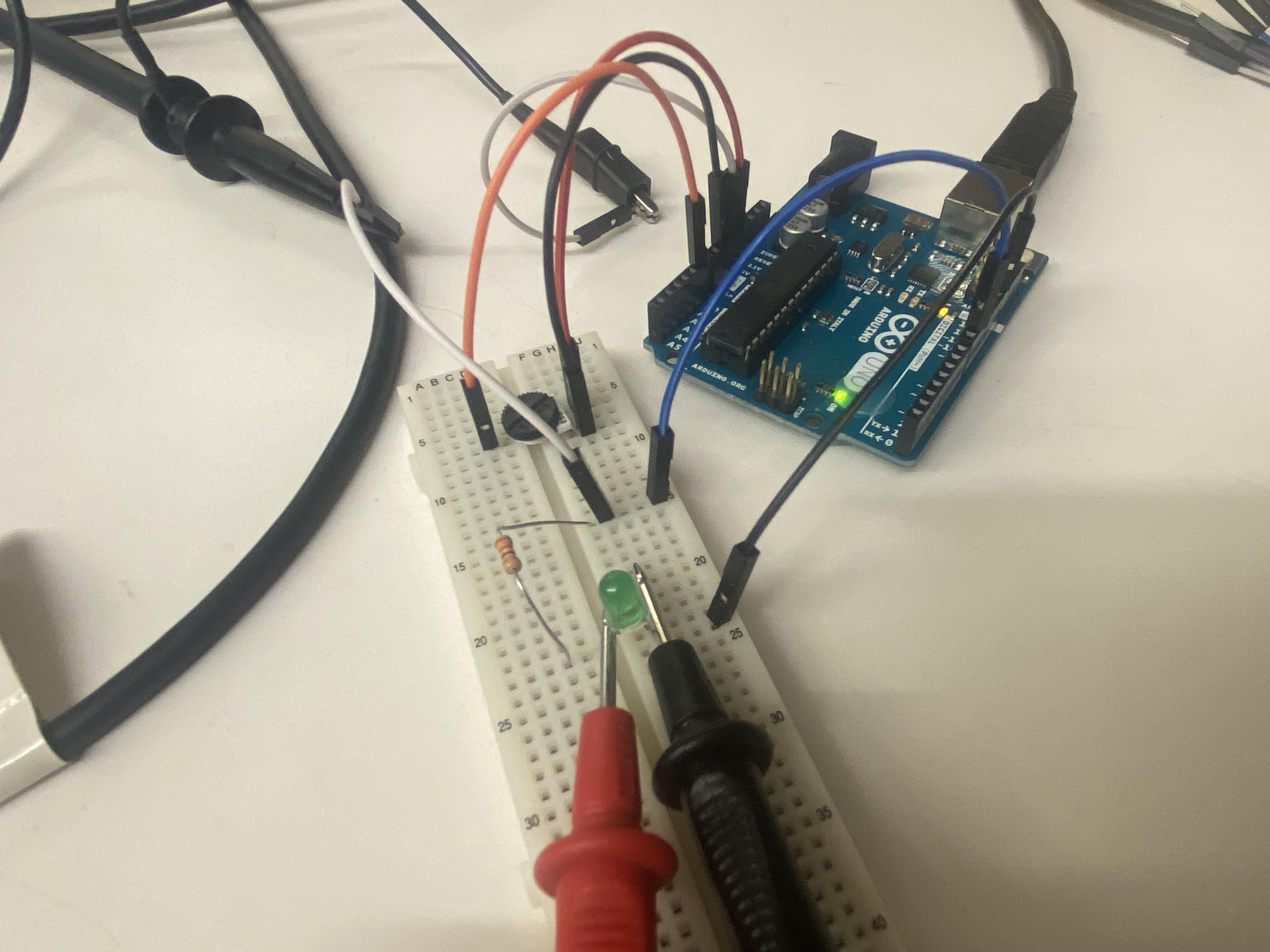
We used a similar setup to last week's, except we added an LED wired to one of the Arduino's PWM pins. The analog input from the potentiometer determined the PWM output and thus brightness of the LED.
We took 11 data points from 0 to 255 on the potentiometer, incrementing by 25 each time (minus the last, where we jumped from 225 to 255). The potentiometer actually output from 0 to 1023, but we divided the reading by 4 so it would work with the PWM output to the LED. We printed the value of the potentiometer to the serial monitor to ensure we were correctly incrementing the analog level. The data from our tests is shown below:
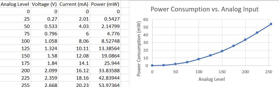
The power consumption increased with the brightness of the LED as expected, peaking at about 54 mW. The Arduino documentation says that the digital output pins can provide a steady 20 mA and operate at 5V. As such, at maximum brightness we can estimate our LED setup to have about 54% efficiency. Based on the voltage drop across the LED at maximum brightness, we can estimate that the forward voltage is approximately 2.6V, which is within a normal range for a green LED.
This is the code we used to test the LED's power consumption.
void setup() {
  // put your setup code here, to run once:
  pinMode(A0, INPUT);
  pinMode(9, OUTPUT);
  Serial.begin(115200);
}

void loop() {
  // put your main code here, to run repeatedly:
int pot = analogRead(A0)/4;
analogWrite(9, pot);
Serial.println(pot);
delay(100);
}