Week 14 - Wildcard
As we are reaching the final spurt for How to Make and finals weeks are killing most of us, I tried to take it relatively low-key this week. Originally, I had thought of doing TinyML on the Xiao ESP32S3 to recognize when a user was calling it, similar to “Hey, Siri.” However, that was just an extra (which I think I could do on my own after HTMAA) and I had really wanted to do what was offered in the other wildcards:
- How to Make a Xiao
- Reverse Engineering
How to Make a Xiao (w/ Anthony)
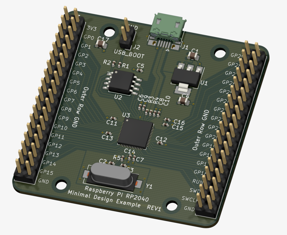
The idea of this wildcard was to fabricate really small boards. “Small” means something different to everyone, as Anthony and I discussed. In this case, we were talking about small components and small traces that are yet still millable - or laserable. Examples of such components would include the actual RP2040 chip.
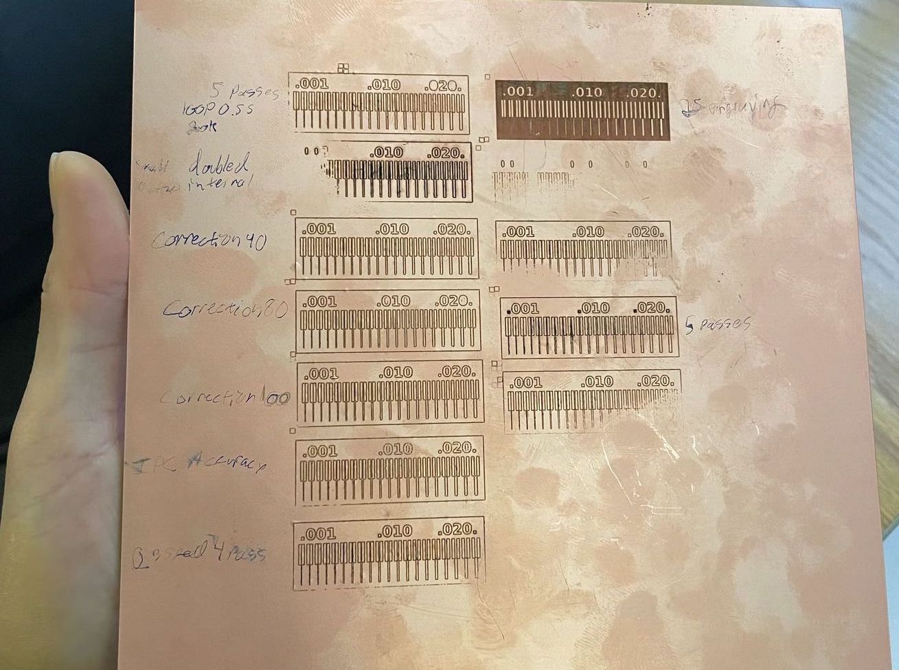
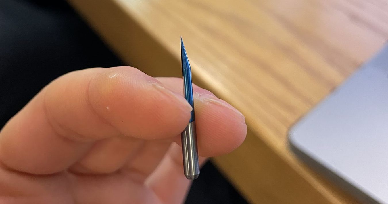
Unfortunately, the lasers we (CBA/EECS) had available either needed maintanance or weren’t really available. The option we had was to mill with a 10 mil endmill or engraving bits (Neil and Anthony don’t like them, they are like endmills but without any threads).
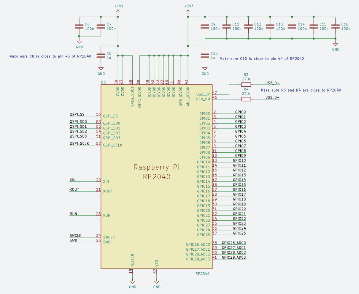
Anthony walked us through the Hardware Design with RP2040 document, which was really insightful. I aim to watch the recording of the session again and/or go through the doc in depth.
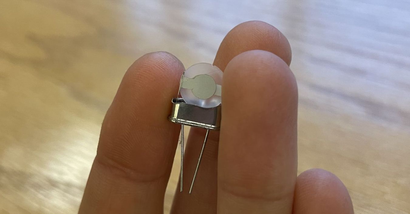
One part I was most curious about, materially, was the crystal. It’s responsible for reliable clocking. It’s nice that Anthony had a crystal available to show us.
However, I couldn’t get myself to design and assemble a new board. This week was really too busy. I decided to go with the reverse engineering option instead.
Reverse Engineering (w/ David)
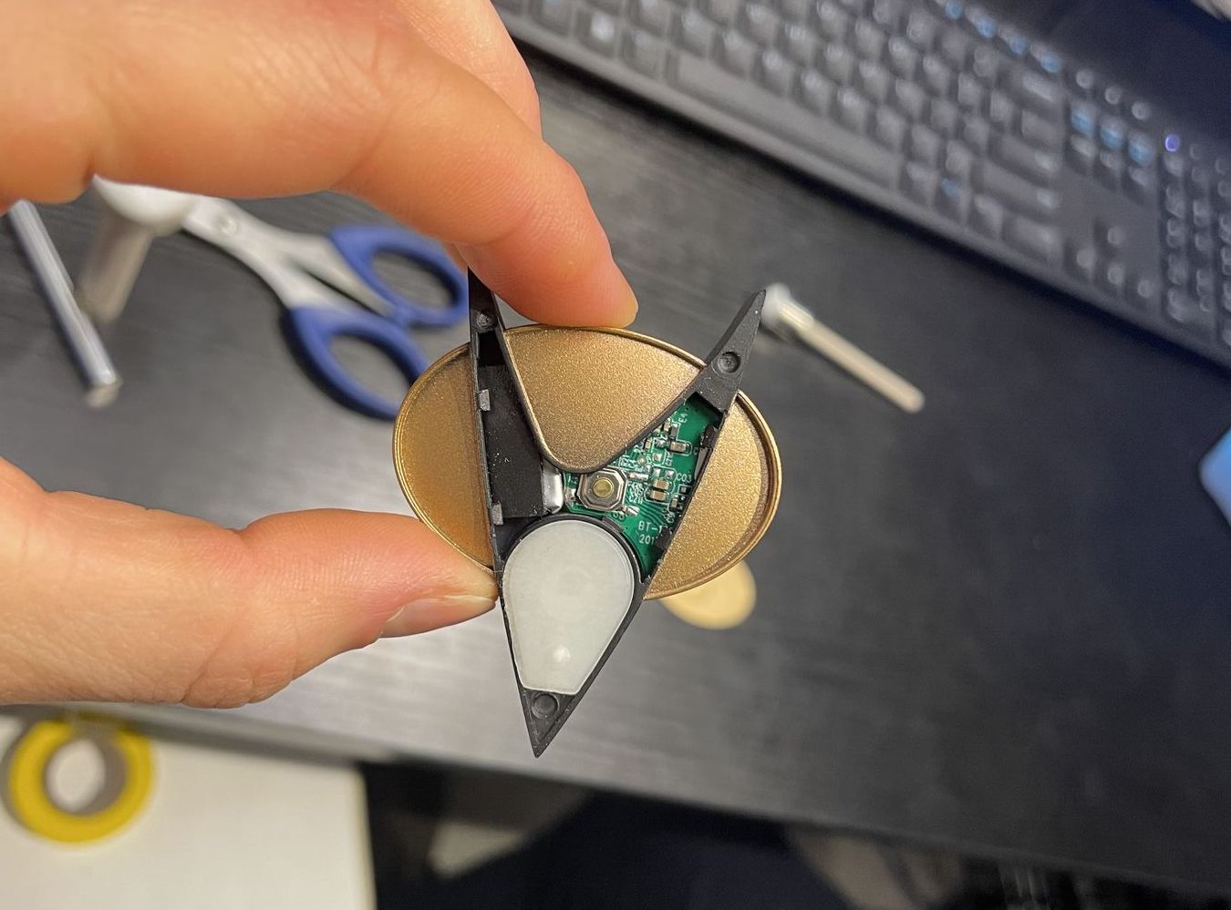
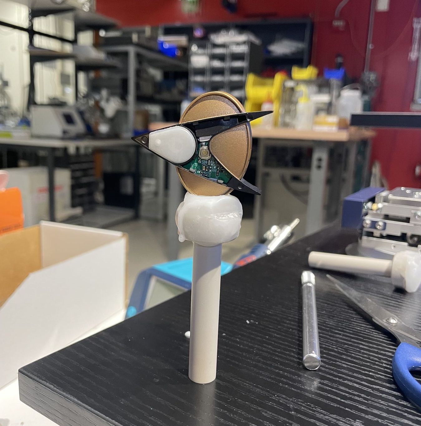
I had been hoping to CT scan the COMBADGE Star Trek badge. The device has most capabilities that I need for my final project (microphone, speaker, capacative touch, battery, charger, bluetooth, etc.) and its neat how they assembled it. The device is very light and small. I was curious to see how they managed to fit everything in there.
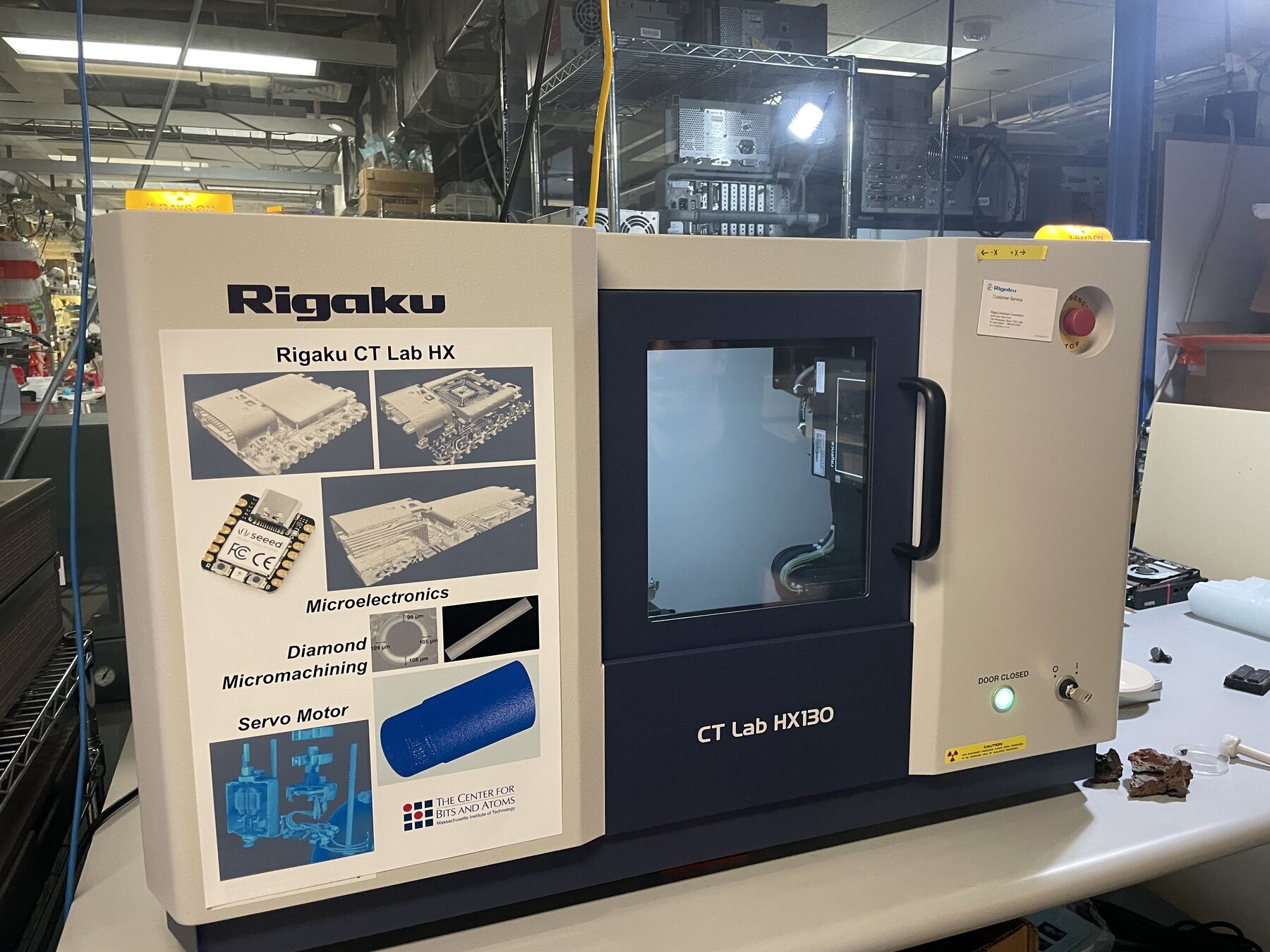
Dave helped me to CT scan it in the CBA (cool space).
CT Scanning
The way a CT scanner works is that it takes a series of X-ray images from different angles and then reconstructs the 3D image from that. The X-ray images are taken by a detector that is placed opposite of the X-ray source. The X-ray source and the detector are then rotated around the object. The X-ray source is a tube that emits X-rays. The detector is a flat panel detector that is made up of a scintillator and a photodiode array. The scintillator converts the X-rays into visible light. The photodiode array then converts the visible light into an electrical signal. The electrical signal is then digitized and sent to a computer. The computer then reconstructs the 3D image from the 2D images. (Thanks Copilot for the explanation!)
We stuck the Combadge onto wax to mount it in the scanner.
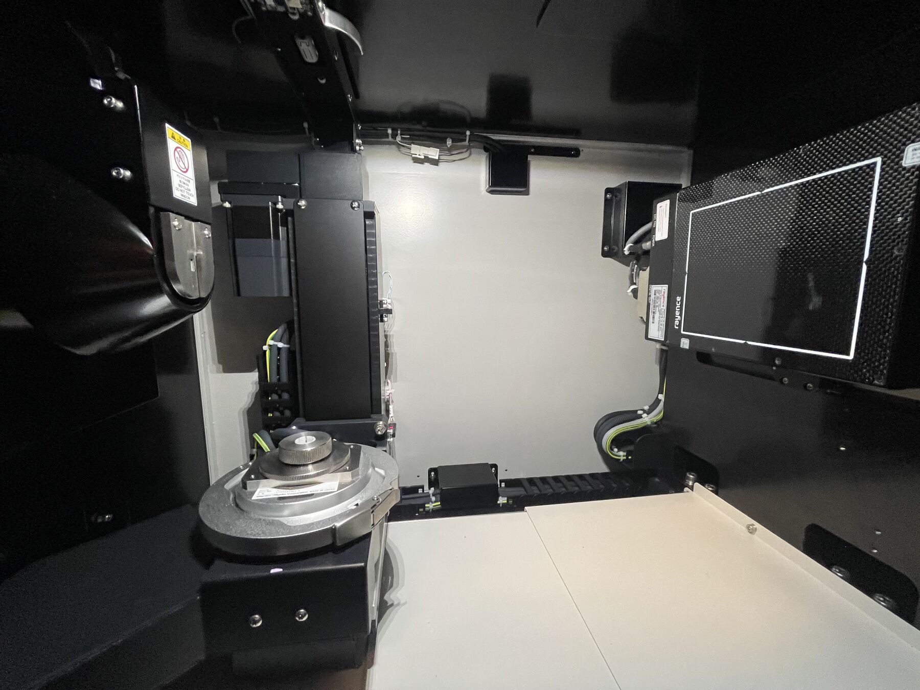
We could then control the positioning and lighting parameters of the object via the CT scanner software. Crucicically, the x-rays are emitted as a cone. Therefore, we need to move an object far enough back so that the entire object is within the cone. Otherwise, we’d only get a partial scan.
We can modify the voltage and current of the X-ray source to change the resolution of the scan. The higher the voltage and current, the better we will see high-desity materials that absorb X-rays, such as metal. As a trade-off, materials such as plastic will be harder to see. We can also change the speed of the rotation of the X-ray source and detector - slower scans will have a higher resolution (they even wobble the object a bit to get a better scan).
The actual scan is a 360 degree scan of the object. The scanner takes several 2D images and, similar to a point cloud, reconstructs a 3D image by calculating the distance of each point from the X-ray source.
Results
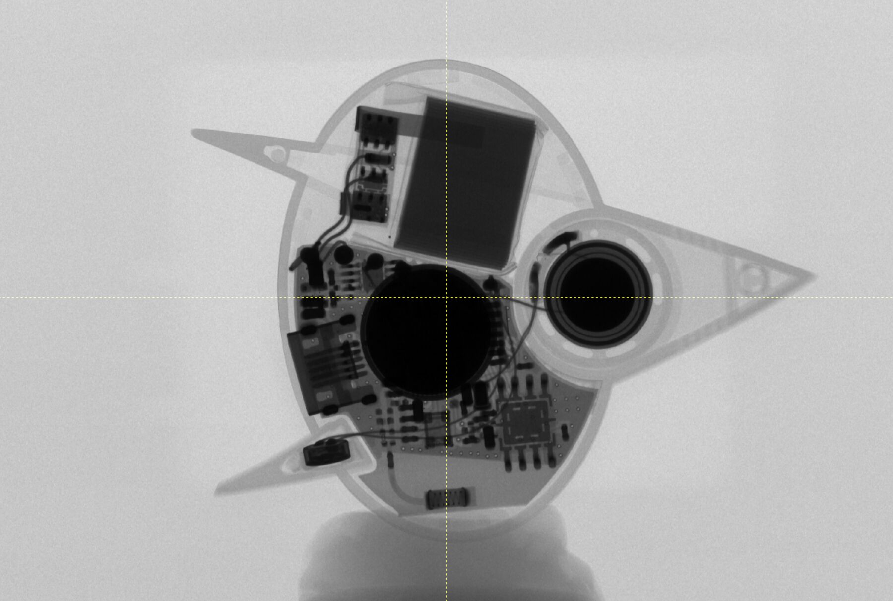
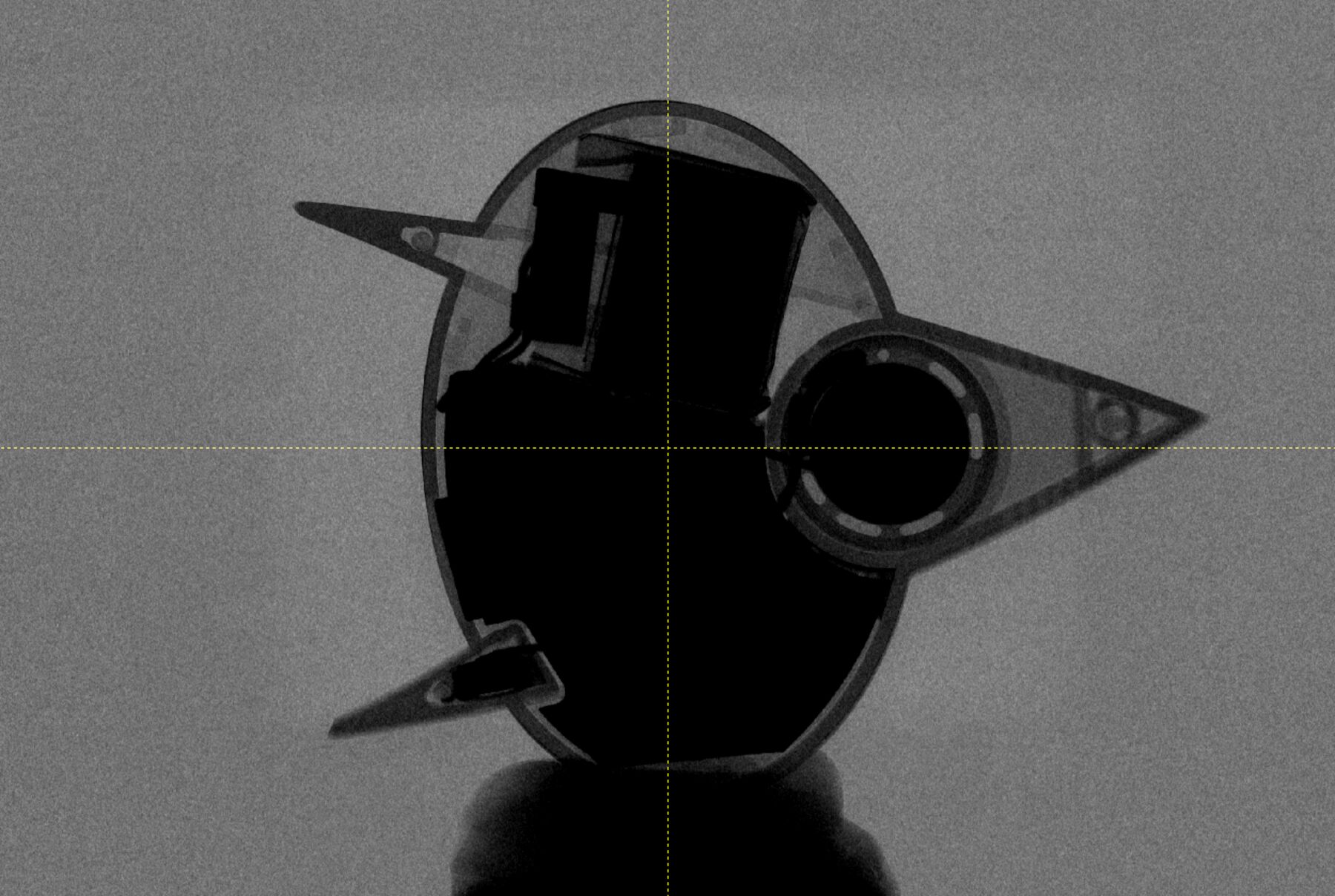
First, we could rotate through the images taken from all sides. Look at what we found here:
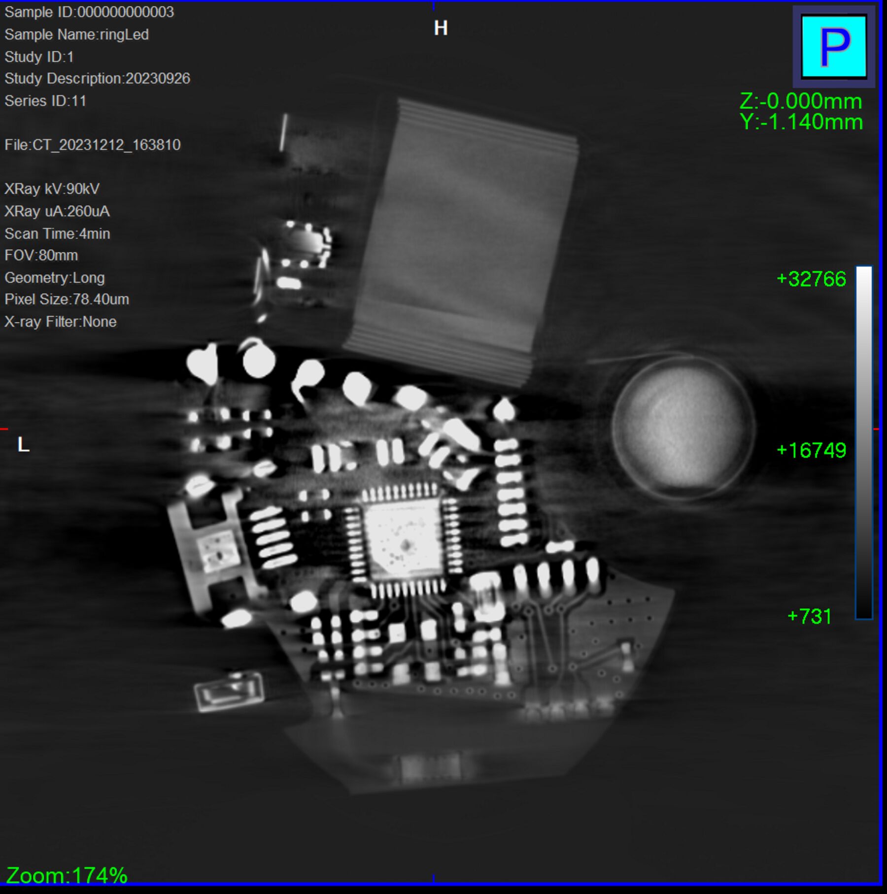 That’s where the processor for the Combadge is! From the top view, it was hidden behind the magnet (which was high density so very dark in the scan).
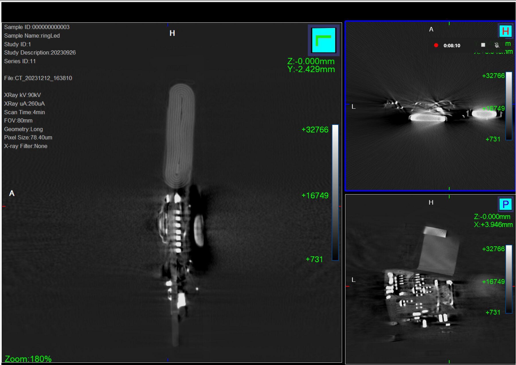 The battery is also visible here. Isn’t it cool how we can see the multiple layers of the LiPo battery?
Second, we could reconstruct a 3D representation of the scan. We could control how much of the scan we wanted to include by controlling for the cutoff value along the absorption spectrum.
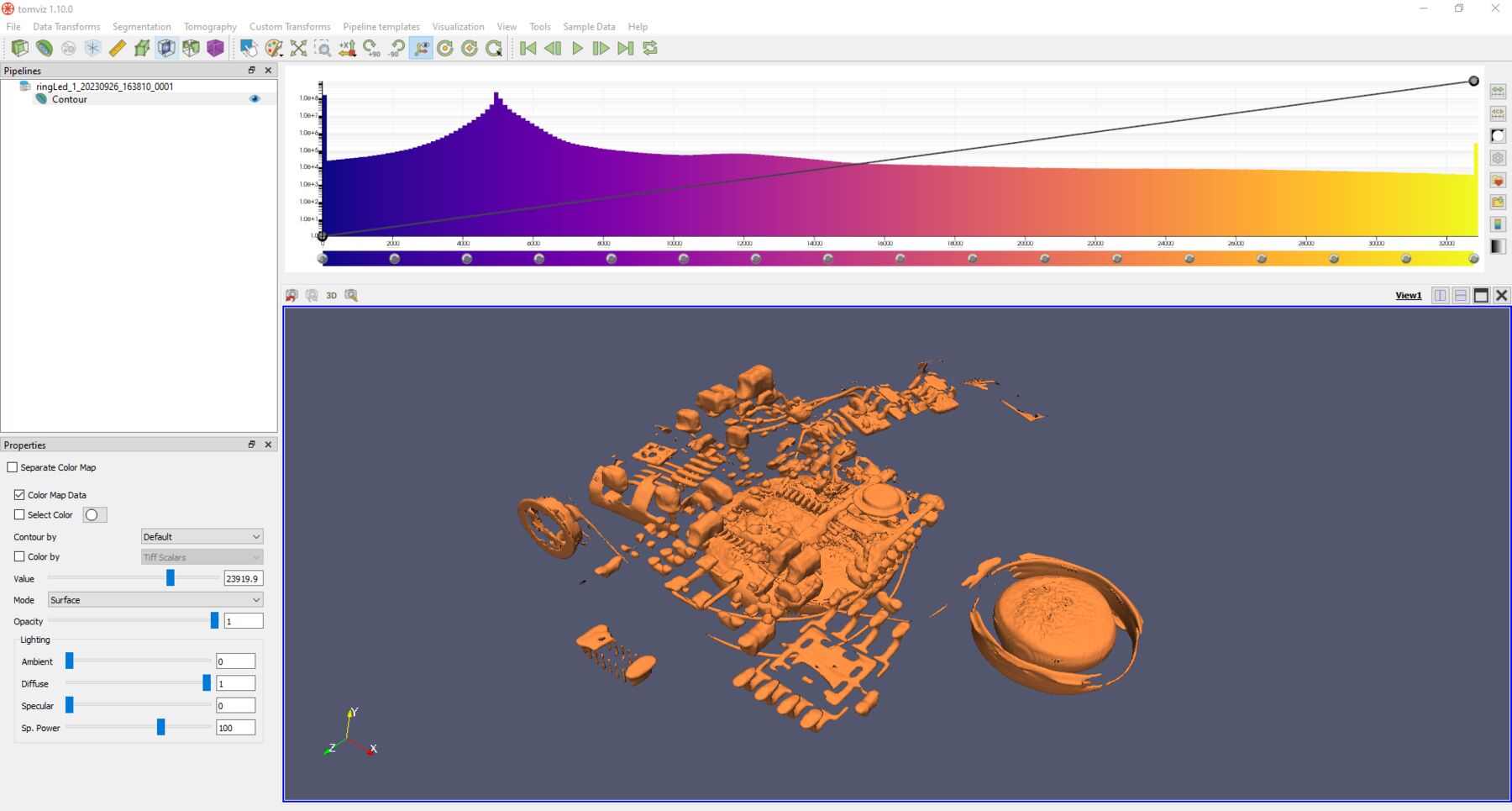
We could even export an entire STL with the electronics inside! That’s crazy.
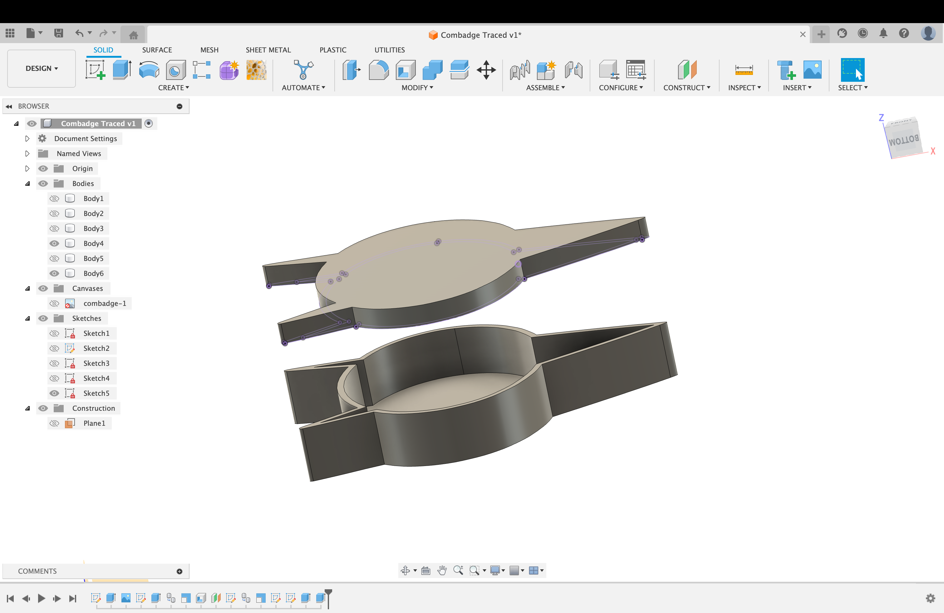
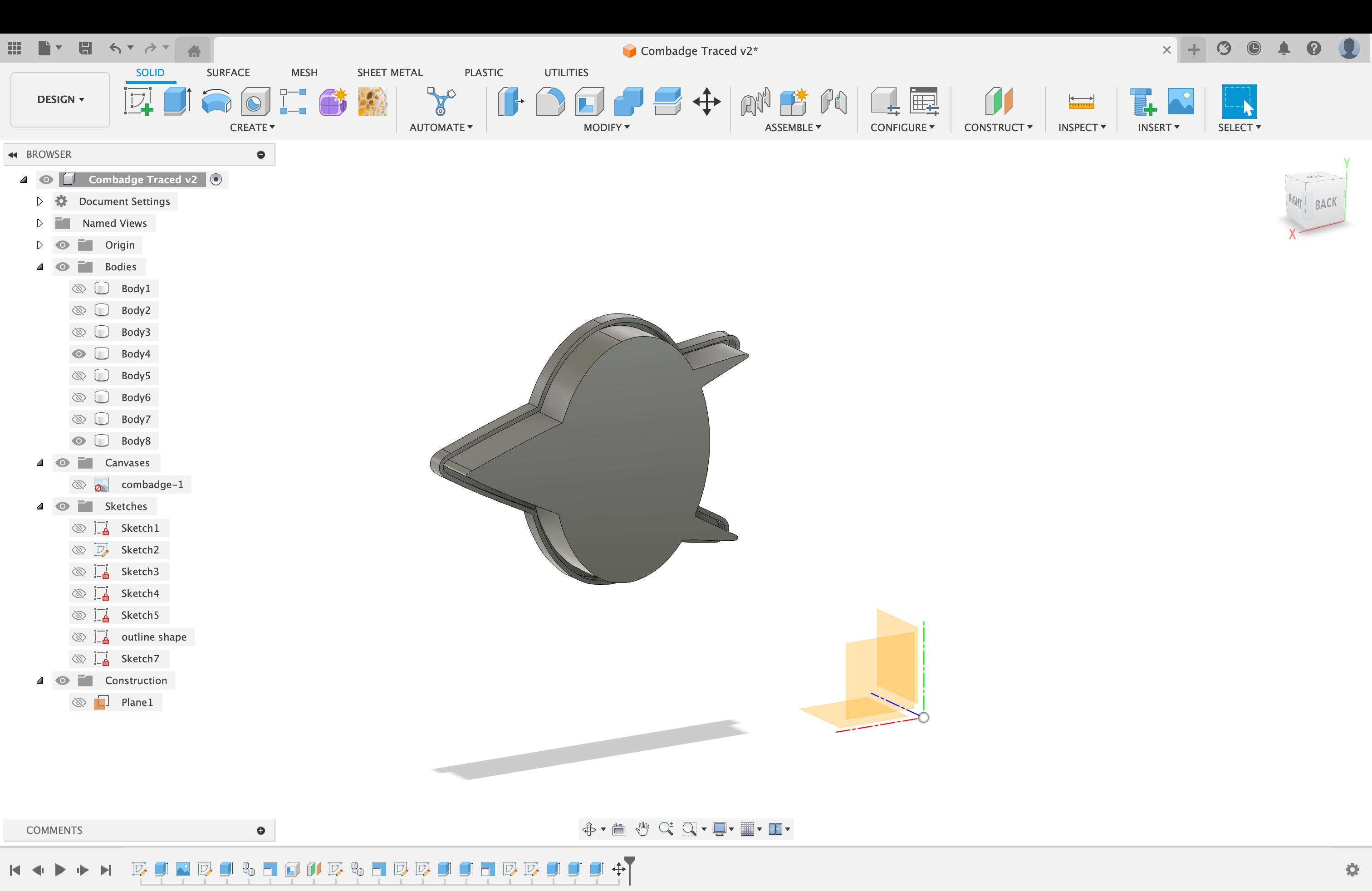
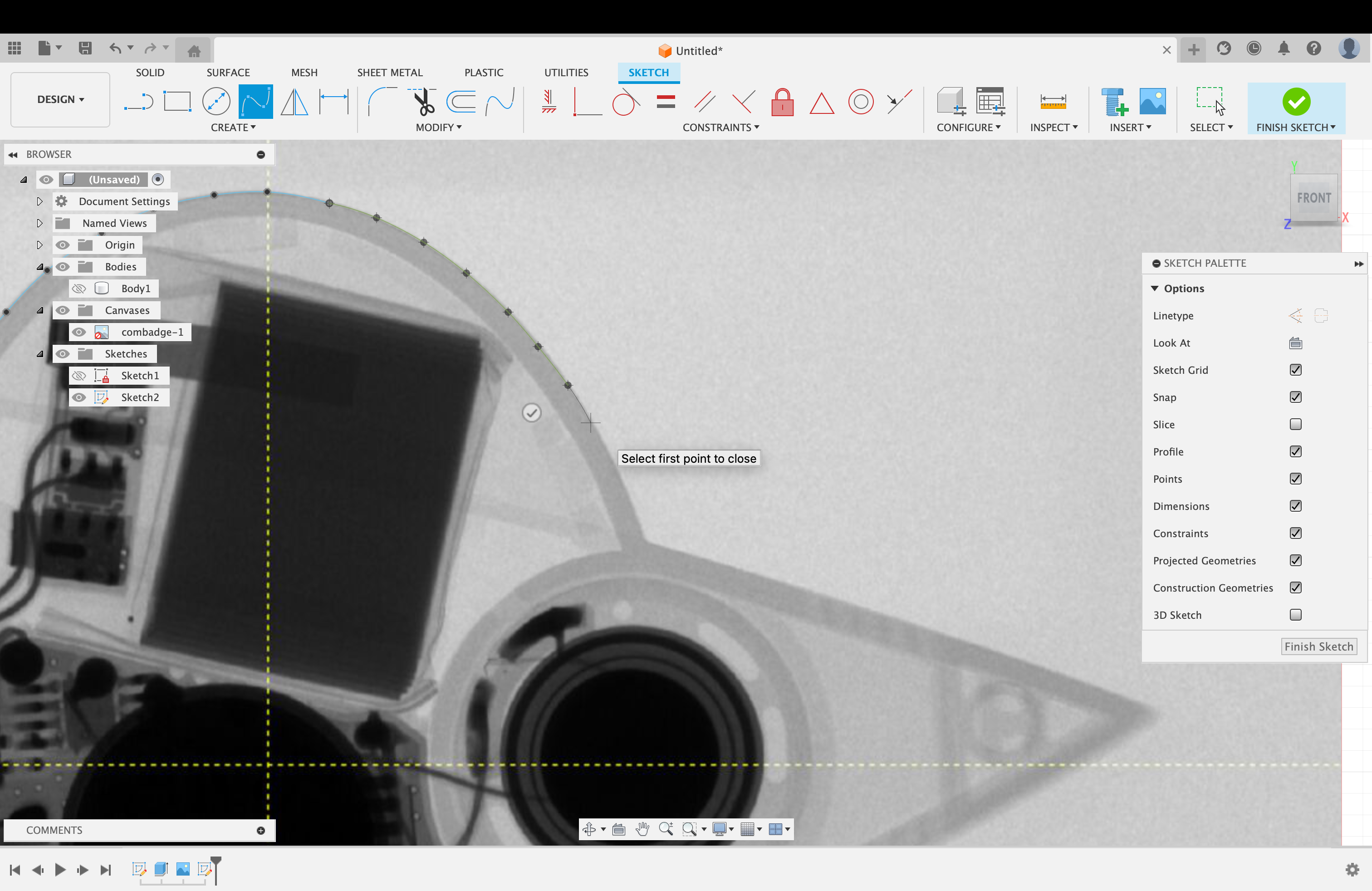
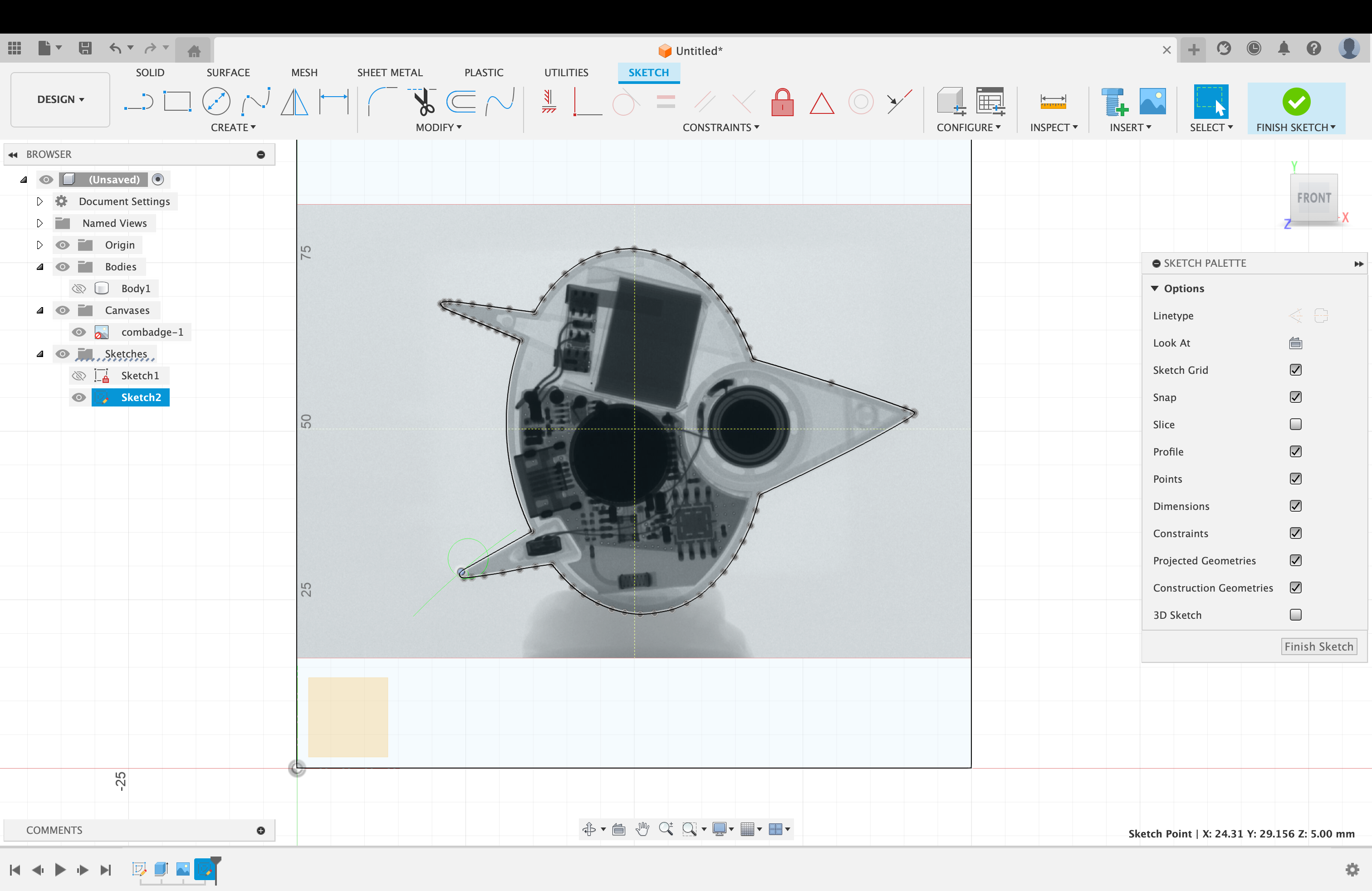
Tracing the shape in Fusion 360
Since the assigment includes a manufacturing component, David suggested I trace the shape in Fusion and 3D print it. I had wanted to use that shape for my final project anyway and make a transparent badge, so I was happy to do that.
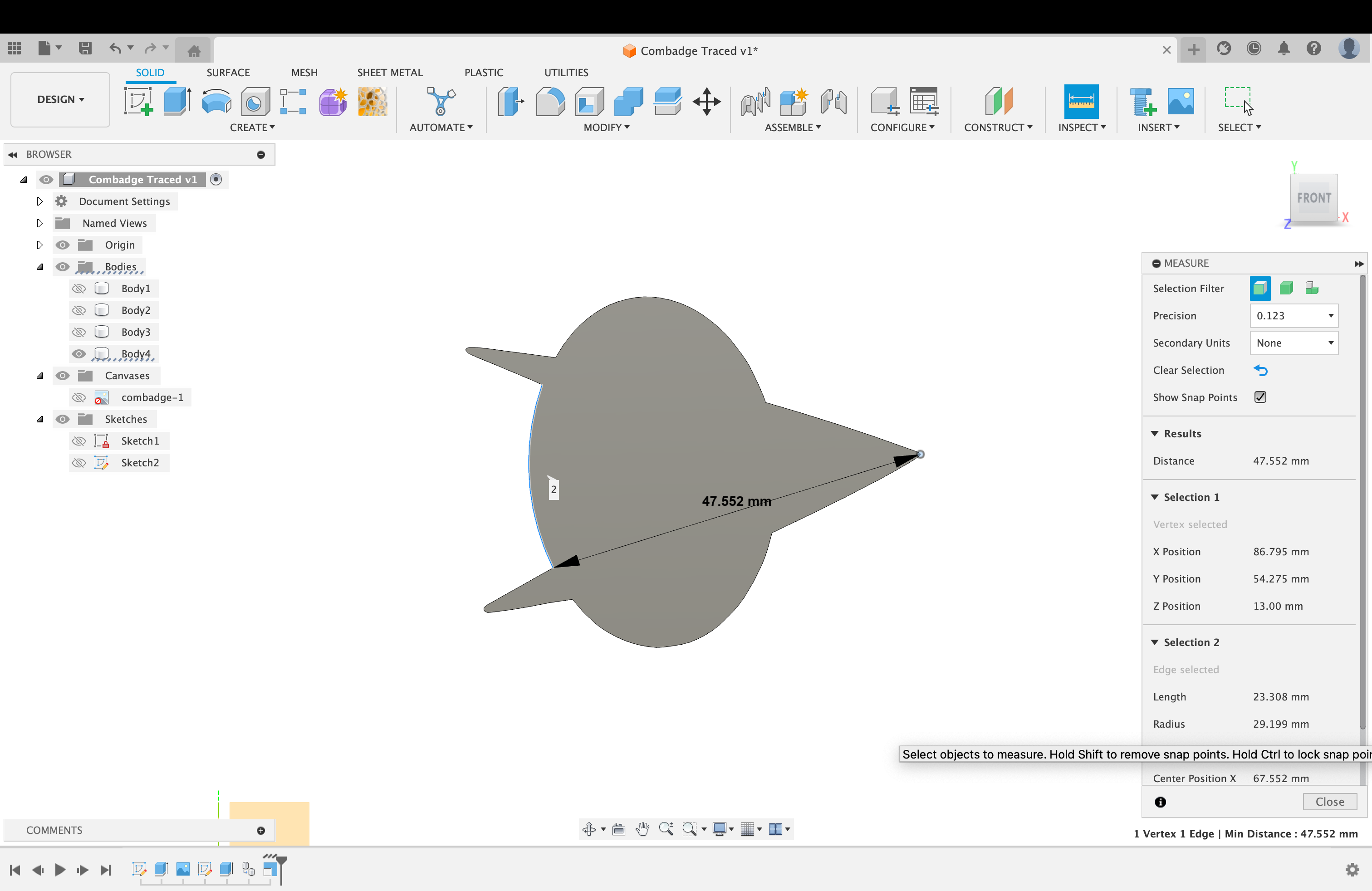
I then extruded the shape and created a lid for it (using Project and Offset).