Week 10: Output devices
Background
For this assignment, we were asked to add an output device to a microcontroller board we’ve designed and program it to do something.
Materials
Idea
Similarly to last week, I was really focused on progressing my final project this week. In the last 7 days, I sought out creating a system that would 1) actuate motors and 2) light up LED strips in response to recognizing a human face, which was… a pretty tall order. That said, I was able to get 80% of the way there and feel pretty excited about the progress in general.
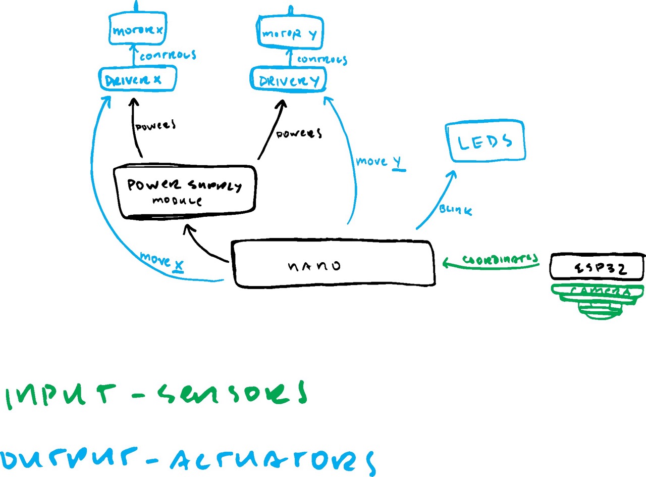
Just like last week, I started this whole process by sketching out all the components in the device (pictured left) and what pieces were specifically serving as outputs.
Setting up computer vision
This step had more to do with setting up input devices, but I think it’s an important part to include in the documentation of this week because the outputs of the computer vision algorithm is what will end up controlling the stepper motors and LEDs.
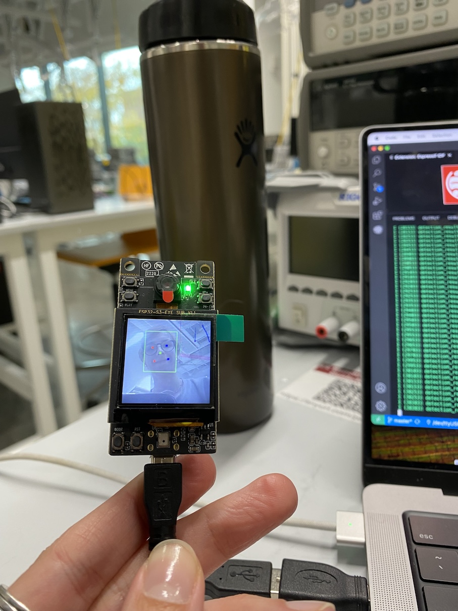
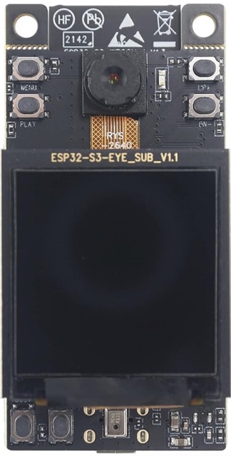
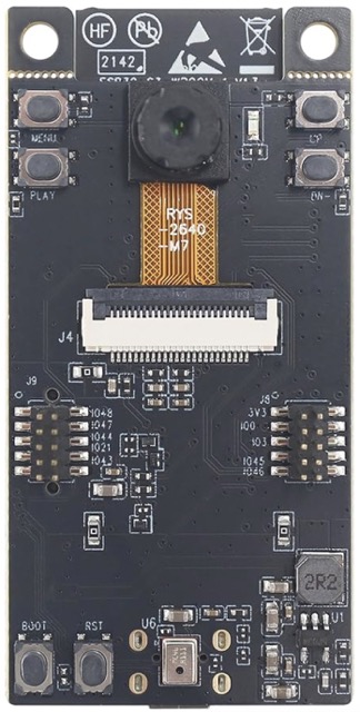
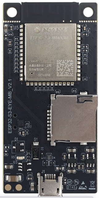
As a refresher, I did a lot of research over the past few weeks to figure out what microcontroller would be best to support light machine learning and image processing tasks on chip. I ended up landing on the ESP32-S3-EYE development kit (pictured below), which at first glance was exactly what I was looking for. As you’ll come to find later in the documentation here, it didn’t end up being the best choice.
I started this whole process by following this tutorial to set up ESP-IDF, which is a software development environment for hardware based on ESP32-S3 chips by Espressif. This process was fairly annoying to do given I had to revert a number of versions of Python packages on my computer, but I eventually did it by uninstalling all python packages and reinstalling based on the requirement/dependency text file in the repository.
After that, I went on to start setting up ESP-WHO following this tutorial, which is an image processing development platform for Espressif chips. It’s really nice because it contains computer vision examples that can be applied to a variety of applications like gesture detection, color detection, and most importantly, human face detection.
Once I had my environment set up, then I could start tweaking the code on a template face detection program to spit out the datapoints I want. I ended up taking the midpoint between the left and right eye of whoever was in view of the camera to get a rough estimate of where the viewer is looking. I averaged the coordinates of these two datapoints, then spat them out in a way another microcontroller could understand.
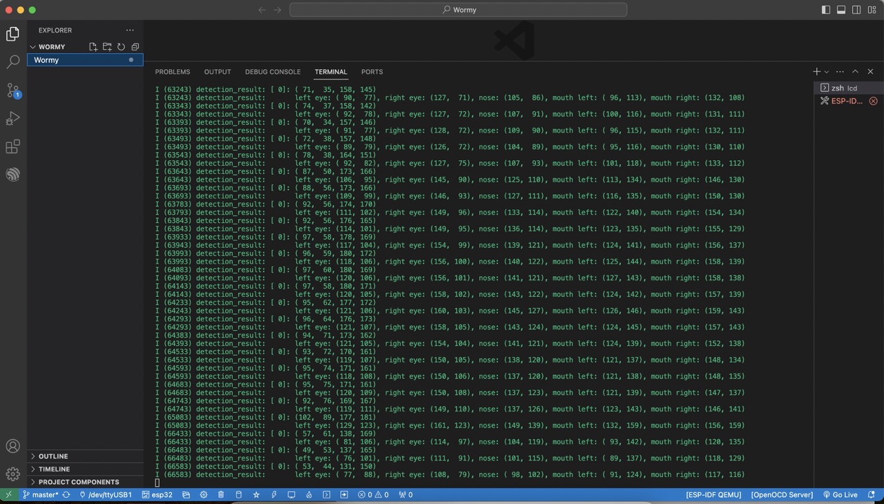
I got so excited after I’d gotten my basic computer vision program up and running that it took me a moment to realize that the ESP32-S3-EYE doesn’t actually have any pins to communicate directly with another microcontroller (board shown below). It was disappointing to learn that this would have to be done over wifi or BLE, given the potential latency of communication… and also because it meant I STILL wouldn’t be able to connect all of my working input with my working output to end up with a real interactive prototype this week. This isn’t a huge problem, I’ll just work on connecting those pieces during the networking week later on in the semester.
Getting motors set up
This is my first time having worked with motors of any kind, so picking what type of motors to use what somewhat difficult. I picked stepper motors because I need precise actuation that DC motors and solenoids wouldn’t be able to give me. I ordered 28BYJ-48 stepper motors with ULN2003 driver boards to match, all powered by a K2 MB-102 power supply module.
Once everything was hooked up on my breadboard correctly, it was difficult to find the right initialization order of pins. Some orders made the motors spin in reverse, others didn’t make the motors spin at all (but turned them into hand warmers). I tried every permutation... if you do the math, that's 2^4 = 16 different tries.
It may go without saying, but I highly recommend putting a flag on your motors to make it easier to see them spin, otherwise you’re going to be squinting at your motors as you adjust the rotation speed. Before moving onto the LEDs, I ensured I could control the stepper motors with my joystick.
Getting LED frame set up
Before I actually started coding anything for this, I put together a frame to see how the experience would feel as I pivoted the frame in different angles and distances from a base mirror. It was made with wood, LED strips, and electrical tape for flexible joints.
Similarly to the stepper motors, I tested the motors with the joystick, but for whatever reason I’m not able to power the motors and my LED strip at the same time— only peripheral or the other (depending on whether I’m using the USB-C or 5V power supply module).
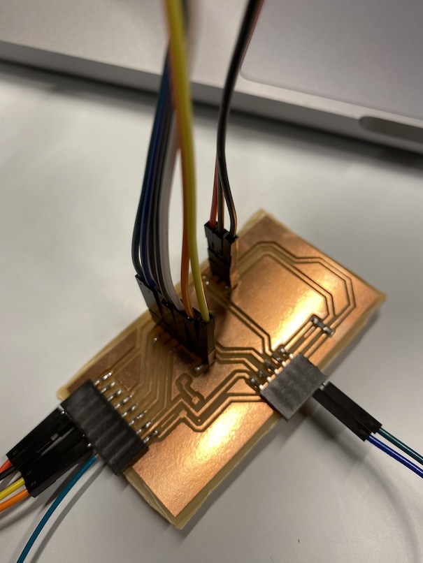
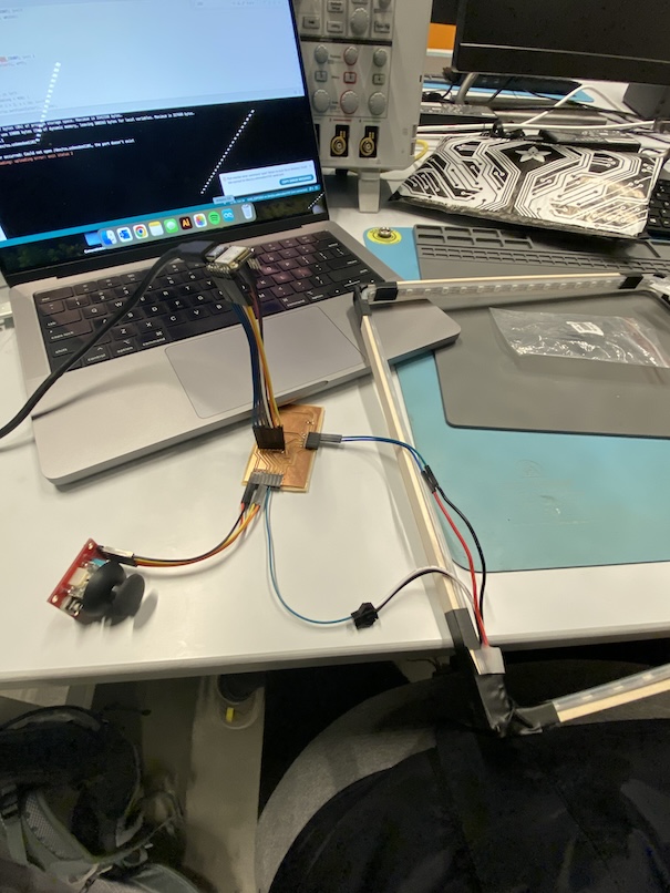
To hook up my LEDs with my PCB to test everything, I milled a new development board (traces and outlines here) that had all the parts I’d need for this week, Input Devices week, and Application/Interface Programming week. I wanted to be able to attach/detach multiple microcontrollers and peripherals with it, which is why it looks a little spaghetti-y.
I created the following sketch to control my peripherals.
Final thoughts
Two thoughts this week:
- I wish I had more time. This is a classic thought most people have in this class, I know. I didn’t get around to soldering my board together, but at least that means when I do solder it to a protoboard (or maybe newly milled PCB) in coming weeks, I’ll have a better idea of how my connections need to be between the ESP32-S3-EYE and the rest of the peripherals.
- Change one goddamn component in your circuit at a time, and know exactly why you’re changing it. Do you need a different microcontroller because yours doesn’t have enough pins? Great! Now find one that solves that issue WHILE MAINTAINING THE SAME FUNCTIONALITY OF YOUR PREVIOUS MICROCONTROLLER. Sure, a Raspberry Pi Pico may have a lot of pins, but does it have the same amount of processing power? What kind of current does it draw? Is it able to communicate with the peripherals elsewhere on your board, or will it just create issues for you later?