Week 3: Embedded programming
Background
For this project, we were asked to write a program for a microcontroller development board that enables it to interact with local input and/or output. For bonus points, we could use different languages, explore new development environments, or attach external components.
Materials
Reading the datasheet
Before starting any development, it's important to read the datasheet for the components that you're working in order to understand the architecture and language you should use when attempting to communicate with the components various subparts in later programming steps. If the datasheet feels too complicated, I recommend going to this site that breaks down the datasheet.
Things I got confused about
As I went through this process of reading the datasheet, I had a number of questions bobbling around my head so I've decided to write them down in the hopes that they help you.
- Microcontroller vs. Microprocessor: despite my background as a computer scientist, I've had very little education when it comes to computer architecture, so I was still a little fuzzy on the difference between a microcontroller and microprocessor. Simply put, a microcontroller is basically an all inclusive system that could function as a computer on its own- it has memory, input, output, and so on. A microprocessor is a subpart of the microcontroller in many ways-- it has to use a system bus or some other means of interfacing with other parts of the chip like the serial interface, the timer, I/O ports, etc. (ADD SKETCH)
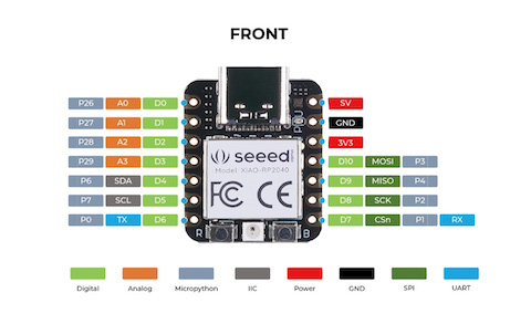
- Pin naming: across data sheets and programs, you may have noticed a variation in the way pins are numbered and referred to. My Arduino sketch could say pin 3, but the data sheet could actually be referencing pin 26. So, why don't they line up? Well, we have different naming conventions to reference different perspectives we're viewing the pin from.
- PIN: viewing the pins as numbered on the board (ex. my board has '2' written on this GPIO pin)
- BCM: viewing the pins as numbered by the chip on the microcontroller (ex. the Raspberry Pi datasheet says we should be referencing this part of the microprocessor using this pin)
- XIAO RP2040 vs. Raspberry Pi Pico: I saw these mentioned interchangeably across numerous tutorials online but ended up finding out that both of the boards actually contain an RP2040 chip and both are compatible with many of the same IDEs. That said, there are a number of the differences including price (the XIAO is more expensive), size (the XIAO is smaller), and pin number (the XIAO has fewer pins). (ADD SKETCH)
Hardware setup
Once I had a better understanding of the components I was working with, I moved on to the hardware setup. This is a very simple process.
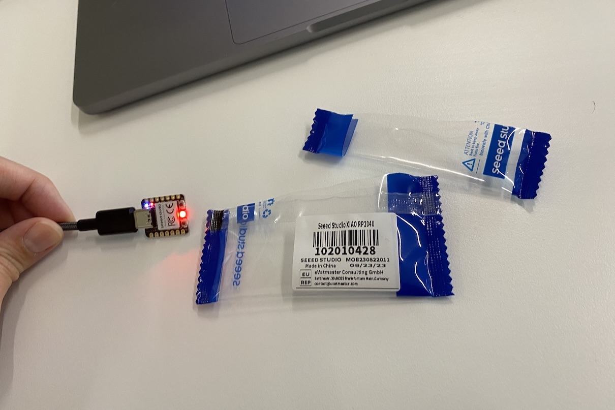
- Press and hold the boot button (labeled 'B' in the bottom right of board) as you connect the RP2040 to your PC with the USB-C cable.
- You should be able to see the device in your finder.
Software setup
Once the hardware has been set up, we can move on to the software.
- Install and open whatever IDE you feel like using. In this case, I used the Arduino IDE but you could just as well use Visual Studio, Raspberry Pi IDE, etc.
- Add Seeed Studio XIAO RP2040 board package to the IDE by navigating to Arduino IDE > Settings and under 'Additional Boards Manager URLs' copy and paste the following URL: https://github.com/earlephilhower/arduino-pico/releases/download/global/package_rp2040_index.json
- Install the latest version of the board package you just added by navigating to Tools > Board > Boards Manager and searching for "Raspberry Pi Pico/RP2040" and hitting 'Install'.
- Select your board and port so the IDE knows what pieces to connect together hardware-wise. Your board should be under Tools > Board and called "Raspberry Pi Pico/RP2040".
- To test everything, open up a sample program (or "sketch") created by Arduino. This is found under File > Examples > 01. Basics > Blink
- Upload the sketch and verify your results by checking to see if the LED on the RP2040 is blinking red once every second.